Page 2584 of 4378
SPECIFICATIONS
SECTION 307-
02: Transaxle/Transmission Cooling 2003 Mustang Workshop Manual General Specifications
Item Specification
Fluid
MERCON® V Automatic Transmission Fluid XT
-5-QM MERCON® V
Torque Specifications Description Nm lb-
ft Fluid cooler tube nut at radiator 32 24
Cooler line bracket to engine nut 48 35
Fluid cooler tube nut at transmission 21 15 �K�l�j . 1 �b�a
12003 Mustang Workshop Manual
18. 11. 2011file:///C:/Ford/2000 - 2004/tsocache/SHEF_2748/S3B~us~en~ ...
Page 2585 of 4378
DESCRIPTION AND OPERATION
Transmission Cooling —
Integral
This vehicle with an automatic transmission is equipped with an integral transmission fluid cooler. The
cooler is contained inside of the radiator outlet tank and cannot be serviced separately. The cooler
transfers heat from the transmission fluid to the engine coolant.
For transmission fluid cooler flow test, refer to Section 307 - 01 .
For transmmission fluid cooler backflushing and cleaning, refer to Section 307 - 01 .
Transmission Fluid Cooler Tubes SECTION 307-
02: Transaxle/Transmission Cooling 2003 Mustang Workshop Manual Item Part Number Description
1 — Fluid cooler inlet tube
2 — Fluid cooler outlet tube
3 7005 Transmission case
4 — Transmission case fittings �K�l�j . 1 �b�a
22003 Mustang Workshop Manual
18. 11. 2011file:///C:/Ford/2000 - 2004/tsocache/SHEF_2748/S3B~us~en~ ...
Page 2587 of 4378

DIAGNOSIS AND TESTING
Transmission Cooling
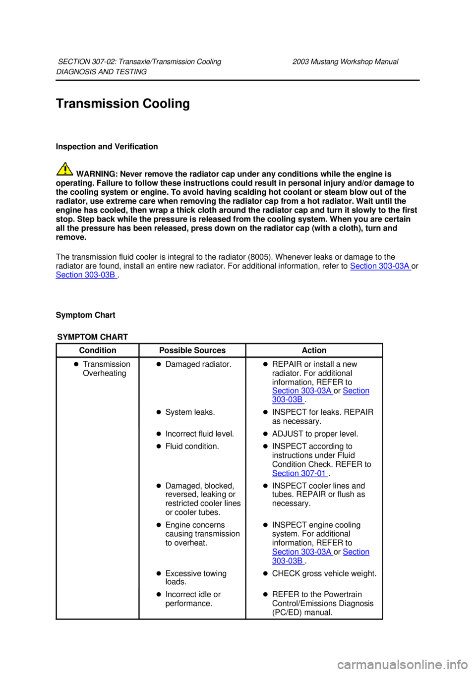
Inspection and Verification
WARNING: Never remove the radiator cap under any conditions while the engine is
operating. Failure to follow these instructions could result in personal injury and/or damage to
the cooling system or engine. To avoid having scalding hot coolant or steam blow out of the
radiator, use extreme care when removing the radiator cap from a hot radiator. Wait until the
engine has cooled, then wrap a thick cloth around the radiator cap and turn it slowly to the first
stop. Step back while the pressure is released from the cooling system. When you are certain
all the pressure has been released, press down on the radiator cap (with a cloth), turn and
remove.
The transmission fluid cooler is integral to the radiator (8005). Whenever leaks or damage to the
radiator are found, install an entire new radiator. For additional information, refer to Section 303 - 03A or
Section 303 - 03B .
Symptom Chart SECTION 307-
02: Transaxle/Transmission Cooling 2003 Mustang Workshop Manual SYMPTOM CHART
Condition
Possible Sources Action
�z Transmission
Overheating �z
Damaged radiator. �zREPAIR or install a new
radiator. For additional
information, REFER to
Section 303 - 03A or
Section 303 - 03B .
�z System leaks. �zINSPECT for leaks. REPAIR
as necessary.
�z Incorrect fluid level. �zADJUST to proper level.
�z Fluid condition. �zINSPECT according to
instructions under Fluid
Condition Check. REFER to
Section 307 - 01 .
�z Damaged, blocked,
reversed, leaking or
restricted cooler lines
or cooler tubes. �z
INSPECT cooler lines and
tubes. REPAIR or flush as
necessary.
�z Engine concerns
causing transmission
to overheat. �z
INSPECT engine cooling
system. For additional
information, REFER to
Section 303 - 03A or
Section 303 - 03B .
�z Excessive towing
loads. �z
CHECK gross vehicle weight.
�z Incorrect idle or
performance. �z
REFER to the Powertrain
Control/Emissions Diagnosis
(PC/ED) manual. �K�l�j . 1 �b�a
22003 Mustang Workshop Manual
18. 11. 2011file:///C:/Ford/2000 - 2004/tsocache/SHEF_2748/S3B~us~en~ ...
Page 2589 of 4378
REMOVAL AND INSTALLATION
Transmission Fluid Cooler Tubes
Removal
1. Disconnect the battery cables.
2. Raise and support the vehicle. For additional information, refer to Section 100 - 02 .
3. Remove the nuts.
4. Remove the fluid cooler tube bracket at the engine.
5. NOTE: Use a backup wrench to hold the case fitting secure.
Remove the fluid cooler tubes at the transmission. Installation SECTION 307-
02: Transaxle/Transmission Cooling 2003 Mustang Workshop Manual �K�l�j . 1 �b�a
32003 Mustang Workshop Manual
18. 11. 2011file:///C:/Ford/2000 - 2004/tsocache/SHEF_2748/S3B~us~en~ ...
Page 2590 of 4378
1.
NOTE: Use a backup wrench to hold the case fitting secure.
Install the fluid cooler tubes at the transmission.
2. Install the fluid cooler tube bracket at the engine.
3. Install the nuts.
4. Lower the vehicle.
5. Connect the battery cables.
6. Fill the transmission with fluid and verify proper operation. �zUse Motorcraft MERCON® V Automatic Transmission Fluid XT -5-QM or equivalent
meeting MERCON® V specification. �K�l�j . 2 �b�a
32003 Mustang Workshop Manual
18. 11. 2011file:///C:/Ford/2000 - 2004/tsocache/SHEF_2748/S3B~us~en~ ...
Page 2592 of 4378
SPECIFICATIONS
SECTION 307-
05: Automatic Transaxle/Transmission External Controls 2003 Mustang Workshop Manual Torque Specifications
Description Nm lb-
ft lb-
in Steering Column Nuts 40 30 —
Shift Interlock Cable 7 — 62
Shift Cable Bracket 12 9 — �K�l�j . 1 �b�a
12003 Mustang Workshop Manual
18. 11. 2011file:///C:/Ford/2000 - 2004/tsocache/SHEF_2748/S3B~us~en~ ...
Page 2593 of 4378

DESCRIPTION AND OPERATION
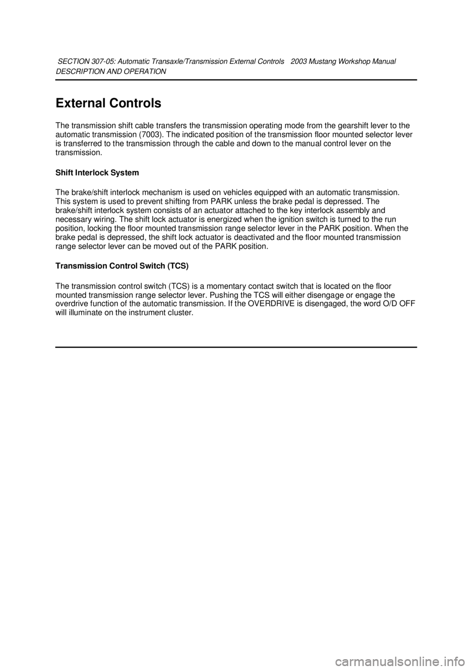
External Controls
The transmission shift cable transfers the transmission operating mode from the gearshift lever to the
automatic transmission (7003). The indicated position of the transmission floor mounted selector lever
is transferred to the transmission through the cable and down to the manual control lever on the
transmission.
Shift Interlock System
The brake/shift interlock mechanism is used on vehicles equipped with an automatic transmission.
This system is used to prevent shifting from PARK unless the brake pedal is depressed. The
brake/shift interlock system consists of an actuator attached to the key interlock assembly and
necessary wiring. The shift lock actuator is energized when the ignition switch is turned to the run
position, locking the floor mounted transmission range selector lever in the PARK position. When the
brake pedal is depressed, the shift lock actuator is deactivated and the floor mounted transmission
range selector lever can be moved out of the PARK position.
Transmission Control Switch (TCS)
The transmission control switch (TCS) is a momentary contact switch that is located on the floor
mounted transmission range selector lever. Pushing the TCS will either disengage or engage the
overdrive function of the automatic transmission. If the OVERDRIVE is disengaged, the word O/D OFF
will illuminate on the instrument cluster.
SECTION 307-
05: Automatic Transaxle/Transmission External Controls 2003 Mustang Workshop Manual �K�l�j . 1 �b�a
12003 Mustang Workshop Manual
18. 11. 2011file:///C:/Ford/2000 - 2004/tsocache/SHEF_2748/S3B~us~en~ ...
Page 2594 of 4378

DIAGNOSIS AND TESTING
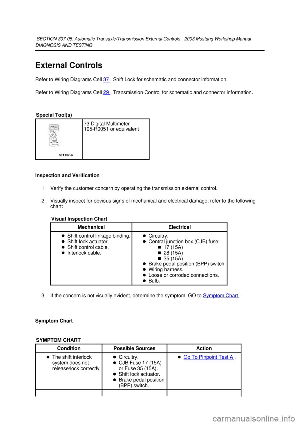
External Controls
Refer to Wiring Diagrams Cell
37 , Shift Lock for schematic and connector information.
Refer to Wiring Diagrams Cell 29 , Transmission Control for schematic and connector information.
Inspection and Verification 1. Verify the customer concern by operating the transmission external control.
2. Visually inspect for obvious signs of mechanical and electrical damage; refer to the following chart:
3. If the concern is not visually evident, determine the symptom. GO to Symptom Chart .
Symptom Chart SECTION 307-
05: Automatic Transaxle/Transmission External Controls 2003 Mustang Workshop Manual Special Tool(s)
73 Digital Multimeter
105-
R0051 or equivalent
Visual Inspection Chart Mechanical Electrical
�z
Shift control linkage binding.
�z Shift lock actuator.
�z Shift control cable.
�z Interlock cable. �z
Circuitry.
�z Central junction box (CJB) fuse:
�„17 (15A)
�„ 28 (15A)
�„ 35 (15A)
�z Brake pedal position (BPP) switch.
�z Wiring harness.
�z Loose or corroded connections.
�z Bulb.
SYMPTOM CHART Condition
Possible Sources Action
�z The shift interlock
system does not
release/lock correctly �z
Circuitry.
�z CJB Fuse 17 (15A)
or Fuse 35 (15A).
�z Shift lock actuator.
�z Brake pedal position
(BPP) switch. �z
Go To Pinpoint Test A . �K�l�j . 1 �b�a
62003 Mustang Workshop Manual
18. 11. 2011file:///C:/Ford/2000 - 2004/tsocache/SHEF_2748/S3B~us~en~ ...