Page 1811 of 4378
59. Install the knock sensor wiring harness.
1. LH knock sensor electrical connector
2. RH knock sensor electrical connector
3. Engine control sensor electrical connector
4. Fuel injector electrical connector
5. A/C compressor electrical connector
6. CKP sensor electrical connector
60. Install the lower intake manifold. �zPosition the gaskets.
�z Install the intake manifold and tighten the bolts in the sequence shown.
61. Install the generator. �K�l�j . 21 �b�a
302003 Mustang Workshop Manual
17. 11. 2011file:///C:/Ford/2000 - 2004/tsocache/SHEF_4464/S3B~us~en~ ...
Page 1813 of 4378
65. Connect the engine coolant temperature (ECT) sensor.
66. Connect the eight fuel injectors.
67. Install the RH ignition coil cover.
68.
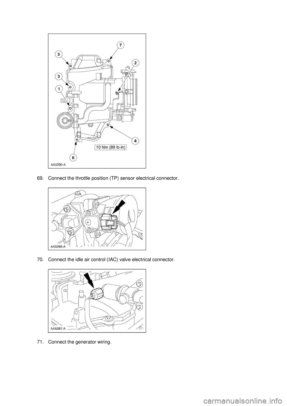
NOTE: The fastener at location five is a stud. Install the gasket and the upper intake. �K�l�j . 23 �b�a
302003 Mustang Workshop Manual
17. 11. 2011file:///C:/Ford/2000 - 2004/tsocache/SHEF_4464/S3B~us~en~ ...
Page 1814 of 4378
69. Connect the throttle position (TP) sensor electrical connector.
70. Connect the idle air control (IAC) valve electrical connector.
71. Connect the generator wiring. �K�l�j . 24 �b�a
302003 Mustang Workshop Manual
17. 11. 2011file:///C:/Ford/2000 - 2004/tsocache/SHEF_4464/S3B~us~en~ ...
Page 1815 of 4378
72. Install the LH coil cover.
73. Connect the EGR vacuum regulator (EVR) electrical connector.
74. Connect the fuel pressure sensor electrical connector.
75. Connect the EGR tube to the exhaust manifold. �K�l�j . 25 �b�a
302003 Mustang Workshop Manual
17. 11. 2011file:///C:/Ford/2000 - 2004/tsocache/SHEF_4464/S3B~us~en~ ...
Page 1822 of 4378
Manual transmission vehicles
2. Install the clutch cable and retaining screws.
All vehicles 3. Raise and support the vehicle. For additional information, refer to Section 100 - 02 .
4. Connect the transmission wiring harness. 1. Connect the RH oxygen sensor connector retainer.
2. Connect the transmission harness electrical connector.
5. NOTE: RH side shown, LH side similar.
Install the LH and RH engine mount nuts. �K�l�j . 2 �b�a
182003 Mustang Workshop Manual
17. 11. 2011file:///C:/Ford/2000 - 2004/tsocache/SHEF_4464/S3B~us~en~ ...
Page 1825 of 4378
13. Install the clutch release lever cover and bolt.
All vehicles 14. Connect the output shaft speed (OSS) sensor electrical connector and attach the left and right oxygen sensor electrical connectors to the crossmember.
15. Connect the reversing lamp switch electrical connector and the wiring harness to the transmission.
16. Remove the two bolts from the RH lifting bracket. �K�l�j . 5 �b�a
182003 Mustang Workshop Manual
17. 11. 2011file:///C:/Ford/2000 - 2004/tsocache/SHEF_4464/S3B~us~en~ ...
Page 1837 of 4378
62. Connect the mass air flow (MAF) sensor electrical connector.
63. Connect the air cleaner outlet pipe at the throttle body.
1. Connect the positive crankcase ventilation (PCV) inlet tube.
2. Tighten the clamp.
64. NOTE: Use reference marks made during removal to aid in the installation.
Install the hood and the four nuts. �K�l�j . 17 �b�a
182003 Mustang Workshop Manual
17. 11. 2011file:///C:/Ford/2000 - 2004/tsocache/SHEF_4464/S3B~us~en~ ...
Page 1841 of 4378
 or equivalent meeting Ford specificatio")
DESCRIPTION AND OPERATION
Engine Cooling
CAUTION: Vehicle cooling systems are filled with Motorcraft Premium Gold Engine
Coolant VC -7-A (in Oregon VC -7-B) or equivalent meeting Ford specification WSS- M97B51-A1
(yellow color). Always fill the cooling system with the same coolant that is present in the
system. Do not mix coolant types.
NOTE: The addition of Motorcraft Cooling System Stop Leak Pellets, VC- 6, darkens Motorcraft
Premium Gold Engine Coolant from yellow to golden tan.
The 4.6L cooling system components include the:
�zblock heater
�z engine coolant temperature (ECT) sensor
�z fan blade, fan motor and fan shroud assembly
�z radiator
�z pressure relief cap
�z radiator draincock
�z coolant pump
�z coolant thermostat
�z oil filter adapter
�z radiator overflow hose
�z upper radiator hose
�z lower radiator hose
The radiator overflow hose circulates the coolant.
The coolant thermostat:
�zcontrols the engine coolant temperature.
�z allows for quicker engine warm- up.
The degas bottle/coolant expansion tank:
�zprovides a location for service fill.
�z contains coolant expansion and system pressurization.
�z provides air separation during operation.
�z replenishes the engine coolant to the system.
The engine coolant flows:
�zfrom the lower radiator hose to the coolant pump.
�z from the coolant pump to the engine block and the cylinder heads.
SECTION 303-
03A: Engine Cooling 2003 Mustang Workshop Manual �K�l�j . 1 �b�a
32003 Mustang Workshop Manual
17. 11. 2011file:///C:/Ford/2000 - 2004/tsocache/SHEF_4464/S3B~us~en~ ...

 sensor.
66. Connect the eight fuel injectors.
67. Install the RH ignition coil cover.
68.
NOTE: The fastener at location five is a stud. Install t")
 electrical connector.
74. Connect the fuel pressure sensor electrical connector.
75. Connect the EGR tube to the exhaust ma")

 sensor electrical connector and attach the left and right oxygen sensor electrical connect")
 sensor electrical connector.
63. Connect the air cleaner outlet pipe at the throttle body.
1. Connect the positive crankcase ventilation (PCV) inlet tube.
2. Tig")