2003 DODGE RAM Lug nuts
[x] Cancel search: Lug nutsPage 28 of 2895

TOWING
STANDARD PROCEDURE - TOWING
A vehicle equipped with SAE approved sling-type
towing equipment can be used to tow all vehicles.
When towing a 4WD vehicle using a wheel-lift towing
device, use tow dollies under the opposite end of the
vehicle. A vehicle with flat-bed device can also be
used to transport a disabled vehicle (Fig. 9).
A wooden crossbeam may be required for proper
connection when using the sling-type, front-end tow-
ing method.
SAFETY PRECAUTIONS
CAUTION: The following safety precautions must be
observed when towing a vehicle:
²Secure loose and protruding parts.
²Always use a safety chain system that is inde-
pendent of the lifting and towing equipment.
²Do not allow towing equipment to contact the
disabled vehicle's fuel tank.
²Do not allow anyone under the disabled vehicle
while it is lifted by the towing device.
²Do not allow passengers to ride in a vehicle
being towed.
²Always observe state and local laws regarding
towing regulations.
²Do not tow a vehicle in a manner that could
jeopardize the safety of the operator, pedestrians or
other motorists.
²Do not attach tow chains, T-hooks, J-hooks, or a
tow sling to a bumper, steering linkage, drive shafts
or a non-reinforced frame hole.
²Do not tow a heavily loaded vehicle. Damage to
the cab, cargo box or frame may result. Use a flatbed
device to transport a loaded vehicle.
GROUND CLEARANCE
CAUTION: If vehicle is towed with wheels removed,
install lug nuts to retain brake drums or rotors.
Fig. 7 FRONT LIFT PAD LOCATION
1 - BODY MOUNT BRACKET
2 - FRONT LIFT PAD
3 - TRANSMISSION CROSSMEMBER BRACKET
4 - FRAME RAIL
Fig. 8 REAR LIFT PAD LOCATION
1 - FRAME RAIL
2 - REAR LIFT PAD
3 - LEAF SPRING MOUNTING BRACKET
4 - BOX MOUNTING BRACKET
Fig. 9 Tow Vehicles With Approved Equipment
1 - SLING TYPE2 - WHEEL LIFT3 - FLAT BED
DRLUBRICATION & MAINTENANCE 0 - 15
HOISTING (Continued)
Page 29 of 2895

A towed vehicle should be raised until lifted wheels
are a minimum 100 mm (4 in) from the ground. Be
sure there is adequate ground clearance at the oppo-
site end of the vehicle, especially when towing over
rough terrain or steep rises in the road. If necessary,
remove the wheels from the lifted end of the vehicle
and lower the vehicle closer to the ground, to
increase the ground clearance at the opposite end of
the vehicle. Install lug nuts on wheel attaching studs
to retain brake drums or rotors.
RAMP ANGLE
If a vehicle with flat-bed towing equipment is used,
the approach ramp angle should not exceed 15
degrees.
TOWING WHEN KEYS ARE NOT AVAILABLE
When the vehicle is locked and keys are not avail-
able, use a flat bed hauler. A Wheel-lift or Sling-type
device can be used on 4WD vehicles providedall the
wheels are lifted off the ground using tow dol-
lies.
FOUR-WHEEL-DRIVE VEHICLE TOWING
Chrysler Corporation recommends that a vehicle be
transported on a flat-bed device. A Wheel-lift or
Sling-type device can be used providedall the
wheels are lifted off the ground using tow dol-
lies.
WARNING: WHEN TOWING A DISABLED VEHICLE
AND THE DRIVE WHEELS ARE SECURED IN A
WHEEL LIFT OR TOW DOLLIES, ENSURE THE
TRANSMISSION IS IN THE PARK POSITION (AUTO-
MATIC TRANSMISSION) OR A FORWARD DRIVE
GEAR (MANUAL TRANSMISSION).
CAUTION: Many vehicles are equipped with air
dams, spoilers, and/or ground effect panels. To
avoid component damage, a wheel-lift towing vehi-
cle or a flat-bed hauling vehicle is recommended.
0 - 16 LUBRICATION & MAINTENANCEDR
TOWING (Continued)
Page 75 of 2895
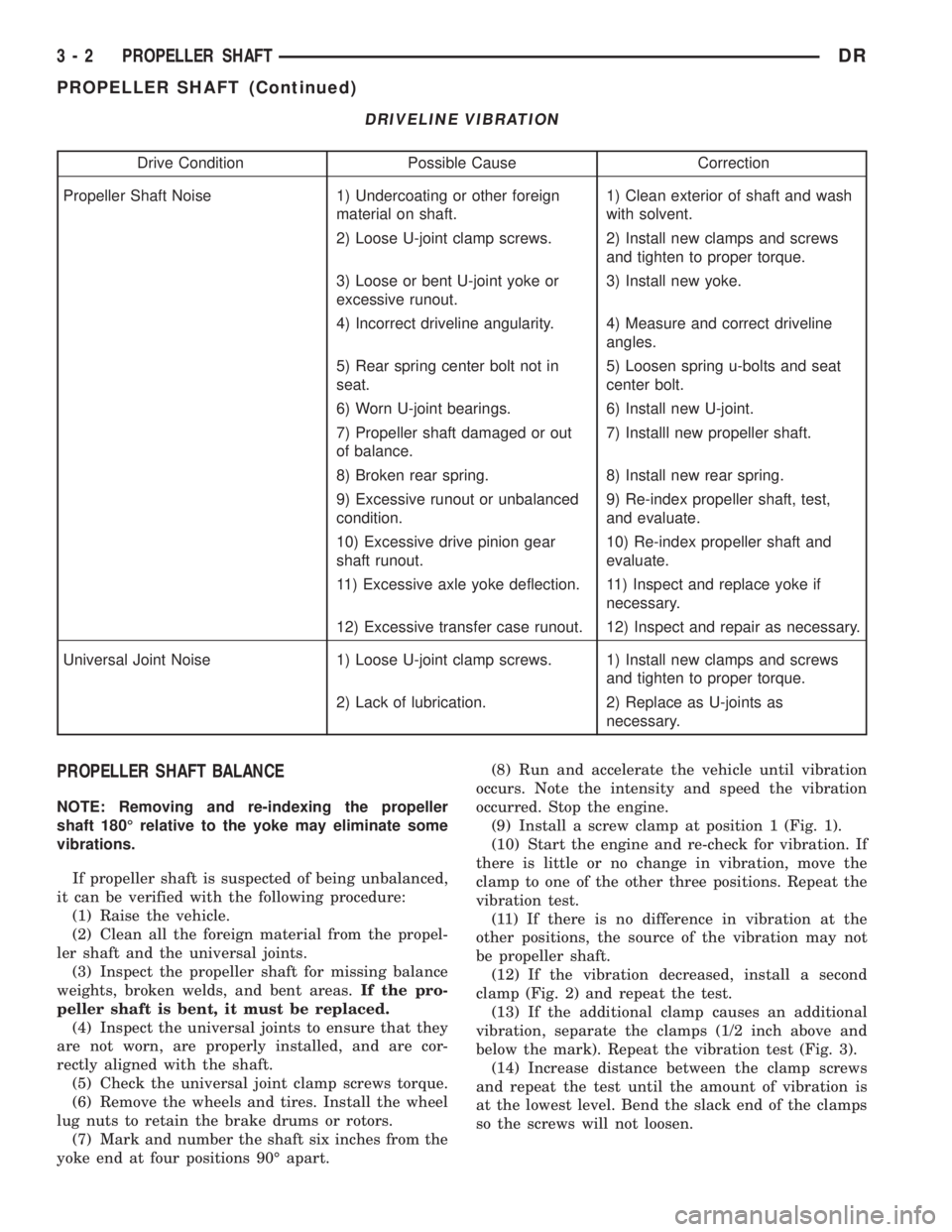
DRIVELINE VIBRATION
Drive Condition Possible Cause Correction
Propeller Shaft Noise 1) Undercoating or other foreign
material on shaft.1) Clean exterior of shaft and wash
with solvent.
2) Loose U-joint clamp screws. 2) Install new clamps and screws
and tighten to proper torque.
3) Loose or bent U-joint yoke or
excessive runout.3) Install new yoke.
4) Incorrect driveline angularity. 4) Measure and correct driveline
angles.
5) Rear spring center bolt not in
seat.5) Loosen spring u-bolts and seat
center bolt.
6) Worn U-joint bearings. 6) Install new U-joint.
7) Propeller shaft damaged or out
of balance.7) Installl new propeller shaft.
8) Broken rear spring. 8) Install new rear spring.
9) Excessive runout or unbalanced
condition.9) Re-index propeller shaft, test,
and evaluate.
10) Excessive drive pinion gear
shaft runout.10) Re-index propeller shaft and
evaluate.
11) Excessive axle yoke deflection. 11) Inspect and replace yoke if
necessary.
12) Excessive transfer case runout. 12) Inspect and repair as necessary.
Universal Joint Noise 1) Loose U-joint clamp screws. 1) Install new clamps and screws
and tighten to proper torque.
2) Lack of lubrication. 2) Replace as U-joints as
necessary.
PROPELLER SHAFT BALANCE
NOTE: Removing and re-indexing the propeller
shaft 180É relative to the yoke may eliminate some
vibrations.
If propeller shaft is suspected of being unbalanced,
it can be verified with the following procedure:
(1) Raise the vehicle.
(2) Clean all the foreign material from the propel-
ler shaft and the universal joints.
(3) Inspect the propeller shaft for missing balance
weights, broken welds, and bent areas.If the pro-
peller shaft is bent, it must be replaced.
(4) Inspect the universal joints to ensure that they
are not worn, are properly installed, and are cor-
rectly aligned with the shaft.
(5) Check the universal joint clamp screws torque.
(6) Remove the wheels and tires. Install the wheel
lug nuts to retain the brake drums or rotors.
(7) Mark and number the shaft six inches from the
yoke end at four positions 90É apart.(8) Run and accelerate the vehicle until vibration
occurs. Note the intensity and speed the vibration
occurred. Stop the engine.
(9) Install a screw clamp at position 1 (Fig. 1).
(10) Start the engine and re-check for vibration. If
there is little or no change in vibration, move the
clamp to one of the other three positions. Repeat the
vibration test.
(11) If there is no difference in vibration at the
other positions, the source of the vibration may not
be propeller shaft.
(12) If the vibration decreased, install a second
clamp (Fig. 2) and repeat the test.
(13) If the additional clamp causes an additional
vibration, separate the clamps (1/2 inch above and
below the mark). Repeat the vibration test (Fig. 3).
(14) Increase distance between the clamp screws
and repeat the test until the amount of vibration is
at the lowest level. Bend the slack end of the clamps
so the screws will not loosen.
3 - 2 PROPELLER SHAFTDR
PROPELLER SHAFT (Continued)
Page 84 of 2895

HALF SHAFT
TABLE OF CONTENTS
page page
HALF SHAFT
CAUTION.............................11
DIAGNOSIS AND TESTING................11
REMOVAL.............................11
INSTALLATION.........................12
SPECIFICATIONS.......................12
SPECIAL TOOLS.......................12CV JOINT-OUTER
REMOVAL.............................13
INSTALLATION.........................13
CV JOINT-INNER
REMOVAL.............................16
INSTALLATION.........................16
HALF SHAFT
CAUTION
CAUTION:: Never grasp half shaft assembly by the
boots. This may cause the boot to pucker or crease
and reduce the service life of the boot.
Avoid over angulating or stroking the C/V joints
when handling the half shaft.
Half shafts exposed to battery acid, transmission
fluid, brake fluid, differential fluid or gasoline may
cause the boots to deteriorate.
DIAGNOSIS AND TESTING
Check for grease at the inboard and outboard C/V
joint. This is a sign of boot or boot clamp damage.
NOISE/VIBRATION IN TURNS
A clicking noise or a vibration in turns could be
caused by a damaged outer C/V or inner tripod joint
seal boot or seal boot clamps. This will result in the
loss/contamination of the joint grease, resulting in
inadequate lubrication of the joint. Noise could also
be caused by another component of the vehicle com-
ing in contact with the half shafts.
CLUNKING NOISE DURING ACCELERATION
This noise may be a result of a damaged or worn
C/V joint. A torn boot or loose/missing clamp on the
inner/outer joint which has allowed the grease to be
lost will damage the C/V joint.
SHUDDER/VIBRATION DURING ACCELERATION
This problem could be a result of a worn/damaged
inner tripod joint or a sticking tripod joint. Improper
wheel alignment may also cause a shudder or vibra-
tion.
VIBRATION AT HIGHWAY SPEEDS
This problem could be a result of out of balance
front tires or tire/wheel runout. Foreign material
(mud, etc.) packed on the backside of the wheel(s)
will also cause a vibration.
REMOVAL
(1) Loosen lug nuts and hub nut while the with
the vehicle brakes applied.
(2) Raise and support the vehicle.
(3) Remove wheel and tire assembly
(4) Remove half shaft hub nut.
(5) Remove brake caliper and rotor.
(6) Position hydraulic jack under lower suspension
arm and raise jack to unload rebound bumper.
(7) Remove lower shock absorber bolt.
(8) Remove upper ball joint nut and seperate ball
with Remover 8677 (Fig. 1).
Fig. 1 UPPER BALL JOINT SEPARATION
1 - UPPER CONTROL ARM
2 - REMOVER
3 - STEERING KNUCKLE
DRHALF SHAFT 3 - 11
Page 92 of 2895

tial bearing noise is also constant and varies only
with vehicle speed.
Axle shaft bearings produce noise and vibration
when worn or damaged. The noise generally changes
when the bearings are loaded. Road test the vehicle.
Turn the vehicle sharply to the left and to the right.
This will load the bearings and change the noise
level. Where axle bearing damage is slight, the noise
is usually not noticeable at speeds above 30 mph.
LOW SPEED KNOCK
Low speed knock is generally caused by a worn
U-joint or by worn side-gear thrust washers. A worn
pinion shaft bore will also cause low speed knock.
VIBRATION
Vibration at the rear of the vehicle is usually
caused by:
²Damaged drive shaft.
²Missing drive shaft balance weight(s).
²Worn or out of balance wheels.
²Loose wheel lug nuts.
²Worn U-joint(s).
²Loose/broken springs.
²Damaged axle shaft bearing(s).
²Loose pinion gear nut.
²Excessive pinion yoke run out.
²Bent axle shaft(s).Check for loose or damaged front end components
or engine/transmission mounts. These components
can contribute to what appears to be a rear end
vibration. Do not overlook engine accessories, brack-
ets and drive belts.
All driveline components should be examined
before starting any repair.
(Refer to 22 - TIRES/WHEELS - DIAGNOSIS AND
TESTING)
DRIVELINE SNAP
A snap or clunk noise when the vehicle is shifted
into gear (or the clutch engaged) can be caused by:
²High engine idle speed.
²Transmission shift operation.
²Loose engine/transmission/transfer case mounts.
²Worn U-joints.
²Loose spring mounts.
²Loose pinion gear nut and yoke.
²Excessive ring gear backlash.
²Excessive side gear to case clearance.
The source of a snap or a clunk noise can be deter-
mined with the assistance of a helper. Raise the vehi-
cle on a hoist with the wheels free to rotate. Instruct
the helper to shift the transmission into gear. Listen
for the noise, a mechanics stethoscope is helpful in
isolating the source of a noise.
DIAGNOSTIC CHART
Condition Possible Causes Correction
Wheel Noise 1. Wheel loose. 1. Tighten loose nuts.
2. Faulty, brinelled wheel bearing. 2. Replace bearing.
Axle Shaft Noise 1. Misaligned axle tube. 1. Inspect axle tube alignment.
Correct as necessary.
2. Bent or sprung axle shaft. 2. Inspect and correct as necessary.
3. End-play in pinion bearings. 3. Refer to pinion pre-load
information and correct as
necessary.
4. Excessive gear backlash
between the ring gear and pinion.4. Check adjustment of the ring
gear and pinion backlash. Correct
as necessary.
5. Improper adjustment of pinion
gear bearings.5. Adjust the pinion bearings
pre-load.
6. Loose pinion yoke nut. 6. Tighten the pinion yoke nut.
7. Scuffed gear tooth contact
surfaces.7. Inspect and replace as
necessary.
DRFRONT AXLE - C205F 3 - 19
FRONT AXLE - C205F (Continued)
Page 103 of 2895
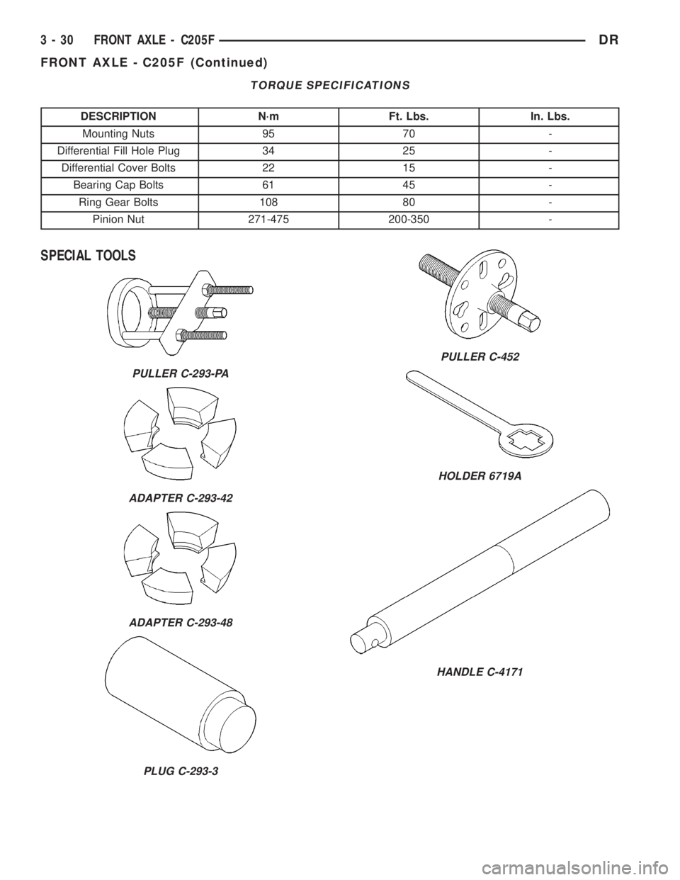
TORQUE SPECIFICATIONS
DESCRIPTION N´m Ft. Lbs. In. Lbs.
Mounting Nuts 95 70 -
Differential Fill Hole Plug 34 25 -
Differential Cover Bolts 22 15 -
Bearing Cap Bolts 61 45 -
Ring Gear Bolts 108 80 -
Pinion Nut 271-475 200-350 -
SPECIAL TOOLS
PULLER C-293-PA
ADAPTER C-293-42
ADAPTER C-293-48
PLUG C-293-3
PULLER C-452
HOLDER 6719A
HANDLE C-4171
3 - 30 FRONT AXLE - C205FDR
FRONT AXLE - C205F (Continued)
Page 119 of 2895
heard during a coast, the front pinion bearing is the
source.
Worn or damaged differential bearings usually pro-
duce a low pitch noise. Differential bearing noise is
similar to pinion bearing noise. The pitch of differen-
tial bearing noise is also constant and varies only
with vehicle speed.
Axle shaft bearings produce noise and vibration
when worn or damaged. The noise generally changes
when the bearings are loaded. Road test the vehicle.
Turn the vehicle sharply to the left and to the right.
This will load the bearings and change the noise
level. Where axle bearing damage is slight, the noise
is usually not noticeable at speeds above 30 mph.
LOW SPEED KNOCK
Low speed knock is generally caused by a worn
U-joint or by worn side-gear thrust washers. A worn
pinion shaft bore will also cause low speed knock.
VIBRATION
Vibration at the front/rear of the vehicle is usually
caused by:
²Damaged drive shaft.
²Missing drive shaft balance weight(s).
²Worn or out of balance wheels.
²Loose wheel lug nuts.
²Worn U-joint(s).²Loose/broken springs.
²Damaged axle shaft bearing(s).
²Loose pinion gear nut.
²Excessive pinion yoke run out.
²Bent axle shaft(s).
Check for loose or damaged front end components
or engine/transmission mounts. These components
can contribute to what appears to be a vibration. Do
not overlook engine accessories, brackets and drive
belts.
DRIVELINE SNAP
A snap or clunk noise when the vehicle is shifted
into gear (or the clutch engaged) can be caused by:
²High engine idle speed.
²Transmission shift operation.
²Loose engine/transmission/transfer case mounts.
²Worn U-joints.
²Loose spring mounts.
²Loose pinion gear nut and yoke.
²Excessive ring gear backlash.
²Excessive side gear to case clearance.
The source of a snap or a clunk noise can be deter-
mined with the assistance of a helper. Raise the vehi-
cle on a hoist with the wheels free to rotate. Instruct
the helper to shift the transmission into gear. Listen
for the noise, a mechanics stethoscope is helpful in
isolating the source of a noise.
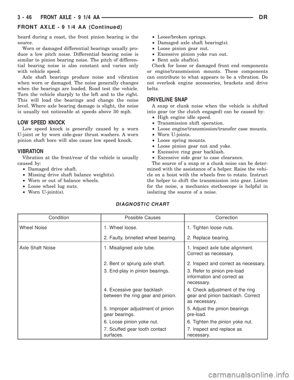
DIAGNOSTIC CHART
Condition Possible Causes Correction
Wheel Noise 1. Wheel loose. 1. Tighten loose nuts.
2. Faulty, brinelled wheel bearing. 2. Replace bearing.
Axle Shaft Noise 1. Misaligned axle tube. 1. Inspect axle tube alignment.
Correct as necessary.
2. Bent or sprung axle shaft. 2. Inspect and correct as necessary.
3. End-play in pinion bearings. 3. Refer to pinion pre-load
information and correct as
necessary.
4. Excessive gear backlash
between the ring gear and pinion.4. Check adjustment of the ring
gear and pinion backlash. Correct
as necessary.
5. Improper adjustment of pinion
gear bearings.5. Adjust the pinion bearings
pre-load.
6. Loose pinion yoke nut. 6. Tighten the pinion yoke nut.
7. Scuffed gear tooth contact
surfaces.7. Inspect and replace as
necessary.
3 - 46 FRONT AXLE - 9 1/4 AADR
FRONT AXLE - 9 1/4 AA (Continued)
Page 144 of 2895
noise will be higher pitched because it rotates at a
faster rate. Drive the vehicle and load the differen-
tial. If bearing noise occurs, the rear pinion bearing
is the source of the noise. If the bearing noise is
heard during a coast, the front pinion bearing is the
source.
Worn or damaged differential bearings usually pro-
duce a low pitch noise. Differential bearing noise is
similar to pinion bearing noise. The pitch of differen-
tial bearing noise is also constant and varies only
with vehicle speed.
Axle shaft bearings produce noise and vibration
when worn or damaged. The noise generally changes
when the bearings are loaded. Road test the vehicle.
Turn the vehicle sharply to the left and to the right.
This will load the bearings and change the noise
level. Where axle bearing damage is slight, the noise
is usually not noticeable at speeds above 30 mph.
LOW SPEED KNOCK
Low speed knock is generally caused by a worn
U-joint or by worn side±gear thrust washers. A worn
pinion shaft bore will also cause low speed knock.
VIBRATION
Vibration at the rear of the vehicle is usually
caused by a:
²Damaged drive shaft.
²Missing drive shaft balance weight(s).
²Worn or out-of-balance wheels.
²Loose wheel lug nuts.
²Worn U-joint(s).²Loose/broken springs.
²Damaged axle shaft bearing(s).
²Loose pinion gear nut.
²Excessive pinion yoke run out.
²Bent axle shaft(s).
Check for loose or damaged front-end components
or engine/transmission mounts. These components
can contribute to what appears to be a rearend vibra-
tion. Do not overlook engine accessories, brackets
and drive belts.
NOTE: All driveline components should be exam-
ined before starting any repair.
DRIVELINE SNAP
A snap or clunk noise when the vehicle is shifted
into gear (or the clutch engaged), can be caused by:
²High engine idle speed.
²Transmission shift operation.
²Loose engine/transmission/transfer case mounts.
²Worn U-joints.
²Loose spring mounts.
²Loose pinion gear nut and yoke.
²Excessive ring gear backlash.
²Excessive side gear to case clearance.
The source of a snap or a clunk noise can be deter-
mined with the assistance of a helper. Raise the vehi-
cle on a hoist with the wheels free to rotate. Instruct
the helper to shift the transmission into gear. Listen
for the noise, a mechanics stethoscope is helpful in
isolating the source of a noise.
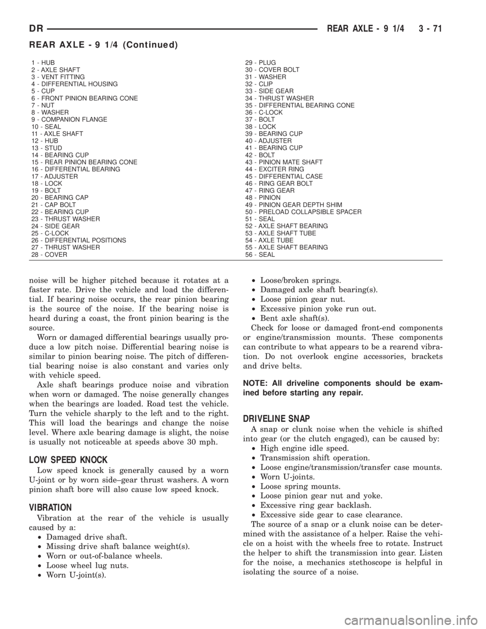
1 - HUB
2 - AXLE SHAFT
3 - VENT FITTING
4 - DIFFERENTIAL HOUSING
5 - CUP
6 - FRONT PINION BEARING CONE
7 - NUT
8 - WASHER
9 - COMPANION FLANGE
10 - SEAL
11 - AXLE SHAFT
12 - HUB
13 - STUD
14 - BEARING CUP
15 - REAR PINION BEARING CONE
16 - DIFFERENTIAL BEARING
17 - ADJUSTER
18 - LOCK
19 - BOLT
20 - BEARING CAP
21 - CAP BOLT
22 - BEARING CUP
23 - THRUST WASHER
24 - SIDE GEAR
25 - C-LOCK
26 - DIFFERENTIAL POSITIONS
27 - THRUST WASHER
28 - COVER29 - PLUG
30 - COVER BOLT
31 - WASHER
32 - CLIP
33 - SIDE GEAR
34 - THRUST WASHER
35 - DIFFERENTIAL BEARING CONE
36 - C-LOCK
37 - BOLT
38 - LOCK
39 - BEARING CUP
40 - ADJUSTER
41 - BEARING CUP
42 - BOLT
43 - PINION MATE SHAFT
44 - EXCITER RING
45 - DIFFERENTIAL CASE
46 - RING GEAR BOLT
47 - RING GEAR
48 - PINION
49 - PINION GEAR DEPTH SHIM
50 - PRELOAD COLLAPSIBLE SPACER
51 - SEAL
52 - AXLE SHAFT BEARING
53 - AXLE SHAFT TUBE
54 - AXLE TUBE
55 - AXLE SHAFT BEARING
56 - SEAL
DRREAR AXLE - 9 1/4 3 - 71
REAR AXLE - 9 1/4 (Continued)