2003 DODGE RAM rough idle
[x] Cancel search: rough idlePage 1740 of 2895
OXYGEN SENSOR
DESCRIPTION
The Oxygen Sensors (O2S) are attached to, and
protrude into the vehicle exhaust system. Depending
on the engine or emission package, the vehicle may
use a total of either 2 or 4 sensors.
Federal Emission Packages :Two sensors are
used: upstream (referred to as 1/1) and downstream
(referred to as 1/2). With this emission package, the
upstream sensor (1/1) is located just before the main
catalytic convertor. The downstream sensor (1/2) is
located just after the main catalytic convertor.
California Emission Packages:On this emis-
sions package, 4 sensors are used: 2 upstream
(referred to as 1/1 and 2/1) and 2 downstream
(referred to as 1/2 and 2/2). With this emission pack-
age, the right upstream sensor (2/1) is located in the
right exhaust downpipe just before the mini-catalytic
convertor. The left upstream sensor (1/1) is located in
the left exhaust downpipe just before the mini-cata-
lytic convertor. The right downstream sensor (2/2) is
located in the right exhaust downpipe just after the
mini-catalytic convertor, and before the main cata-
lytic convertor. The left downstream sensor (1/2) is
located in the left exhaust downpipe just after the
mini-catalytic convertor, and before the main cata-
lytic convertor.
OPERATION
An O2 sensor is a galvanic battery that provides
the PCM with a voltage signal (0-1 volt) inversely
proportional to the amount of oxygen in the exhaust.
In other words, if the oxygen content is low, the volt-
age output is high; if the oxygen content is high the
output voltage is low. The PCM uses this information
to adjust injector pulse-width to achieve the
14.7±to±1 air/fuel ratio necessary for proper engine
operation and to control emissions.
The O2 sensor must have a source of oxygen from
outside of the exhaust stream for comparison. Cur-
rent O2 sensors receive their fresh oxygen (outside
air) supply through the O2 sensor case housing.
Four wires (circuits) are used on each O2 sensor: a
12±volt feed circuit for the sensor heating element; a
ground circuit for the heater element; a low-noise
sensor return circuit to the PCM, and an input cir-
cuit from the sensor back to the PCM to detect sen-
sor operation.
Oxygen Sensor Heater Relay - 5.9L/8.0L:If 4
oxygen sensors are used, a separate heater relay is
used to supply voltage to the sensors heating ele-
ments for only the 1/2 and 2/2 downstream sensors.
Voltage for the other 2 sensor heating elements is
supplied directly from the Powertrain Control Mod-ule (PCM) through a Pulse Width Module (PWM)
method.
Pulse Width Module (PWM) - 5.9L/8.0L:Voltage
to the O2 sensor heating elements is supplied
directly from the Powertrain Control Module (PCM)
through two separate Pulse Width Module (PWM)
low side drivers. PWM is used on both the upstream
and downstream O2 sensors if equipped with a Fed-
eral Emissions Package, and only on the 2 upstream
sensors (1/1 and 2/1) if equipped with a California
Emissions Package. The main objective for a PWM
driver is to avoid overheating of the O2 sensor heater
element. With exhaust temperatures increasing with
time and engine speed, it's not required to have a
full-voltage duty-cycle on the O2 heater elements.
To avoid the large simultaneous current surge
needed to operate all 4 sensors, power is delayed to
the 2 downstream heater elements by the PCM for
approximately 2 seconds.
Oxygen Sensor Heater Elements:
The O2 sensor uses a Positive Thermal Co-efficient
(PTC) heater element. As temperature increases,
resistance increases. At ambient temperatures
around 70ÉF, the resistance of the heating element is
approximately 13 ohms. As the sensor's temperature
increases, resistance in the heater element increases.
This allows the heater to maintain the optimum
operating temperature of approximately 930É-1100ÉF
(500É-600É C). Although the sensors operate the
same, there are physical differences, due to the envi-
ronment that they operate in, that keep them from
being interchangeable.
Maintaining correct sensor temperature at all
times allows the system to enter into closed loop
operation sooner. Also, it allows the system to remain
in closed loop operation during periods of extended
idle.
In Closed Loop operation, the PCM monitors cer-
tain O2 sensor input(s) along with other inputs, and
adjusts the injector pulse width accordingly. During
Open Loop operation, the PCM ignores the O2 sensor
input. The PCM adjusts injector pulse width based
on preprogrammed (fixed) values and inputs from
other sensors.
Upstream Sensor - Federal Emissions Pack-
age :The upstream sensor (1/1) provides an input
voltage to the PCM. The input tells the PCM the oxy-
gen content of the exhaust gas. The PCM uses this
information to fine tune fuel delivery to maintain the
correct oxygen content at the downstream oxygen
sensor. The PCM will change the air/fuel ratio until
the upstream sensor inputs a voltage that the PCM
has determined will make the downstream sensor
output (oxygen content) correct.
The upstream oxygen sensor also provides an input
to determine catalytic convertor efficiency.
DRFUEL INJECTION - GAS 14 - 43
Page 1742 of 2895
INSTALLATION
Threads of new oxygen sensors are factory coated
with anti-seize compound to aid in removal.DO
NOT add any additional anti-seize compound to
threads of a new oxygen sensor.
(1) Install O2S sensor. Tighten to 30 N´m (22 ft.
lbs.) torque.
(2) Connect O2S sensor wire connector.
(3) Lower vehicle.
THROTTLE BODY
DESCRIPTION
The throttle body is located on the intake manifold.
Fuel does not enter the intake manifold through the
throttle body. Fuel is sprayed into the manifold by
the fuel injectors.
OPERATION
Filtered air from the air cleaner enters the intake
manifold through the throttle body. The throttle body
contains an air control passage controlled by an Idle
Air Control (IAC) motor. The air control passage is
used to supply air for idle conditions. A throttle valve
(plate) is used to supply air for above idle conditions.
5.7L V-8 Engine:
The throttle body on the 5.7L engine is an electri-
cally controlled unit. A mechanical cable is not used
to connect the throttle body to the accelerator pedal.
The Accelerator Pedal Position Sensor (APPS) along
with inputs from other sensors sets the throttle blade
to pre-determined positions.
Except 5.7L V-8 Engine:
Certain sensors are attached to the throttle body.
The accelerator pedal cable, speed control cable and
transmission control cable (when equipped) are con-
nected to the throttle body linkage arm.
A (factory adjusted) set screw is used to mechani-
cally limit the position of the throttle body throttle
plate.Never attempt to adjust the engine idle
speed using this screw.All idle speed functions are
controlled by the PCM.
REMOVAL
3.7L V-6
A (factory adjusted) set screw is used to mechani-
cally limit the position of the throttle body throttle
plate.Never attempt to adjust the engine idle
speed using this screw.All idle speed functions are
controlled by the Powertrain Control Module (PCM).
(1) Remove air cleaner tube at throttle body.
(2) Disconnect throttle body electrical connectors
at IAC motor and TPS.(3) Remove all control cables from throttle body
(lever) arm. Refer to the Accelerator Pedal and Throt-
tle Cable section for removal/installation procedures.
(4) Disconnect necessary vacuum lines at throttle
body.
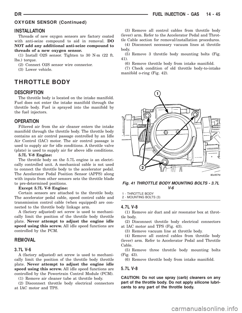
(5) Remove 3 throttle body mounting bolts (Fig.
41).
(6) Remove throttle body from intake manifold.
(7) Check condition of old throttle body-to-intake
manifold o-ring (Fig. 42).
4.7L V-8
(1) Remove air duct and air resonator box at throt-
tle body.
(2) Disconnect throttle body electrical connectors
at IAC motor and TPS (Fig. 43).
(3) Remove vacuum line at throttle body.
(4) Remove all control cables from throttle body
(lever) arm. Refer to Accelerator Pedal and Throttle
Cable.
(5) Remove three throttle body mounting bolts
(Fig. 43).
(6) Remove throttle body from intake manifold.
5.7L V-8
CAUTION: Do not use spray (carb) cleaners on any
part of the throttle body. Do not apply silicone lubri-
cants to any part of the throttle body.
Fig. 41 THROTTLE BODY MOUNTING BOLTS - 3.7L
V-6
1 - THROTTLE BODY
2 - MOUNTING BOLTS (3)
DRFUEL INJECTION - GAS 14 - 45
OXYGEN SENSOR (Continued)
Page 1797 of 2895
DIAGNOSIS AND TESTING - POWER STEERING
FLOW AND PRESSURE
The following procedure is used to test the opera-
tion of the power steering system on the vehicle. This
test will provide the gallons per minute (GPM) or
flow rate of the power steering pump along with the
maximum relief pressure. Perform test any time a
power steering system problem is present. This test
will determine if the power steering pump or power
steering gear is not functioning properly. The follow-
ing pressure and flow test is performed using Power
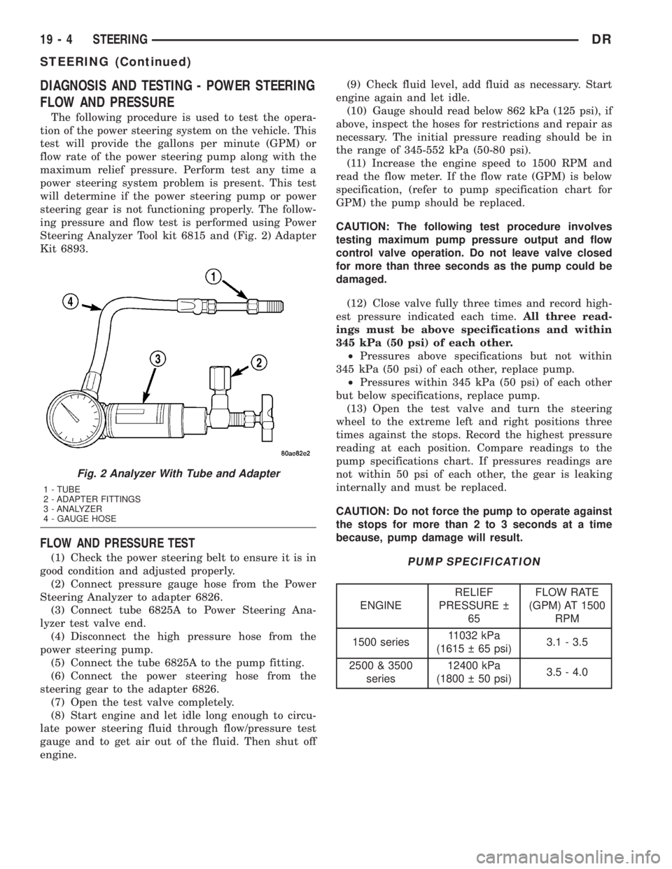
Steering Analyzer Tool kit 6815 and (Fig. 2) Adapter
Kit 6893.
FLOW AND PRESSURE TEST
(1) Check the power steering belt to ensure it is in
good condition and adjusted properly.
(2) Connect pressure gauge hose from the Power
Steering Analyzer to adapter 6826.
(3) Connect tube 6825A to Power Steering Ana-
lyzer test valve end.
(4) Disconnect the high pressure hose from the
power steering pump.
(5) Connect the tube 6825A to the pump fitting.
(6) Connect the power steering hose from the
steering gear to the adapter 6826.
(7) Open the test valve completely.
(8) Start engine and let idle long enough to circu-
late power steering fluid through flow/pressure test
gauge and to get air out of the fluid. Then shut off
engine.(9) Check fluid level, add fluid as necessary. Start
engine again and let idle.
(10) Gauge should read below 862 kPa (125 psi), if
above, inspect the hoses for restrictions and repair as
necessary. The initial pressure reading should be in
the range of 345-552 kPa (50-80 psi).
(11) Increase the engine speed to 1500 RPM and
read the flow meter. If the flow rate (GPM) is below
specification, (refer to pump specification chart for
GPM) the pump should be replaced.
CAUTION: The following test procedure involves
testing maximum pump pressure output and flow
control valve operation. Do not leave valve closed
for more than three seconds as the pump could be
damaged.
(12) Close valve fully three times and record high-
est pressure indicated each time.All three read-
ings must be above specifications and within
345 kPa (50 psi) of each other.
²Pressures above specifications but not within
345 kPa (50 psi) of each other, replace pump.
²Pressures within 345 kPa (50 psi) of each other
but below specifications, replace pump.
(13) Open the test valve and turn the steering
wheel to the extreme left and right positions three
times against the stops. Record the highest pressure
reading at each position. Compare readings to the
pump specifications chart. If pressures readings are
not within 50 psi of each other, the gear is leaking
internally and must be replaced.
CAUTION: Do not force the pump to operate against
the stops for more than 2 to 3 seconds at a time
because, pump damage will result.PUMP SPECIFICATION
ENGINERELIEF
PRESSURE
65FLOW RATE
(GPM) AT 1500
RPM
1500 series11032 kPa
(1615 65 psi)3.1 - 3.5
2500 & 3500
series12400 kPa
(1800 50 psi)3.5 - 4.0
Fig. 2 Analyzer With Tube and Adapter
1 - TUBE
2 - ADAPTER FITTINGS
3 - ANALYZER
4 - GAUGE HOSE
19 - 4 STEERINGDR
STEERING (Continued)
Page 1832 of 2895
DIAGNOSIS AND TESTING - PUMP LEAKAGE
The pump is serviced as an assembly and should
not be disassembled. The plastic pump reservoir and
the reservoir o-rings can be replaced.
Check for leaks in the following areas:
²Pump shaft seal behind the pulley
²Pump to reservoir O-ring
²Reservoir cap
²Pressure and return lines
²Flow control valve fitting
STANDARD PROCEDURE
STANDARD PROCEDURE - POWER STEERING
PUMP - INITIAL OPERATION
WARNING: THE FLUID LEVEL SHOULD BE
CHECKED WITH ENGINE OFF TO PREVENT INJURY
FROM MOVING COMPONENTS.
CAUTION: MOPARTATF+4 is to be used in the
power steering system. No other power steering or
automatic transmission fluid is to be used in the
system. Damage may result to the power steering
pump and system if any other fluid is used, and do
not overfill.
Wipe filler cap clean, then check the fluid level.
The dipstick should indicateCOLDwhen the fluid is
at normal temperature.(1) Turn steering wheel all the way to the left
(2) Fill the pump fluid reservoir to the proper level
and let the fluid settle for at least two (2) minutes.
(3) Raise the front wheels off the ground.
(4) Slowly turn the steering wheel lock-to-lock 20
times with the engine off while checking the fluid
level.
NOTE: For vehicles with long return lines or oil
coolers turn wheel 40 times.
(5) Start the engine. With the engine idling main-
tain the fluid level.
(6) Lower the front wheels and let the engine idle
for two minutes.
(7) Turn the steering wheel in both direction and
verify power assist and quiet operation of the pump.
If the fluid is extremely foamy or milky looking,
allow the vehicle to stand a few minutes and repeat
the procedure.
CAUTION: Do not run a vehicle with foamy fluid for
an extended period. This may cause pump damage.
STANDARD PROCEDURE - FLUSHING POWER
STEERING SYSTEM
Flushing is required when the power steering/hy-
draulic booster system fluid has become contami-
nated. Contaminated fluid in the steering/booster
system can cause seal deterioration and affect steer-
ing gear/booster spool valve operation.
(1) Raise the front end of the vehicle off the
ground until the wheels are free to turn.
(2) Remove the return line from the pump.
NOTE: If vehicle is equipped with a hydraulic
booster remove both return lines from the pump.
(3) Plug the return line port/ports at the pump.
(4) Position the return line/lines into a large con-
tainer to catch the fluid.
(5) While an assistant is filling the pump reservoir
start the engine.
(6) With the engine running at idle turn the wheel
back and forth.
NOTE: Do not contact or hold the wheel against the
steering stops.
(7) Run a quart of fluid through the system then
stop the engine and install the return line/lines.
(8) Fill the system with fluid and perform Steering
Pump Initial Operation, (Refer to 19 - STEERING/
PUMP - STANDARD PROCEDURE).
(9) Start the engine and run it for fifteen minutes
then stop the engine.
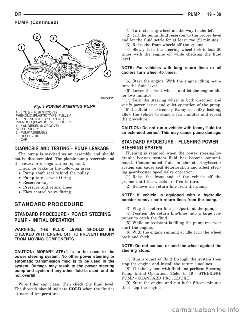
Fig. 1 POWER STEERING PUMP
1 - 3.7L & 4.7L (6 GROOVE)
PHENOLIC (PLASTIC TYPE) PULLEY
1 - 5.7L,5.9L & 8.0L (7 GROOVE)
PHENOLIC (PLASTIC TYPE) PULLEY
1 - 5.9L DIESEL (8 GROOVE)
STEEL PULLEY
2 - PUMP ASSEMBLY
3 - RESERVOIR
4 - CAP
DRPUMP 19 - 39
PUMP (Continued)
Page 1838 of 2895
POWER STEERING PRESSURE
SWITCH
DESCRIPTION
A pressure sensing switch is used in the power
steering system. It is mounted on the high-pressure
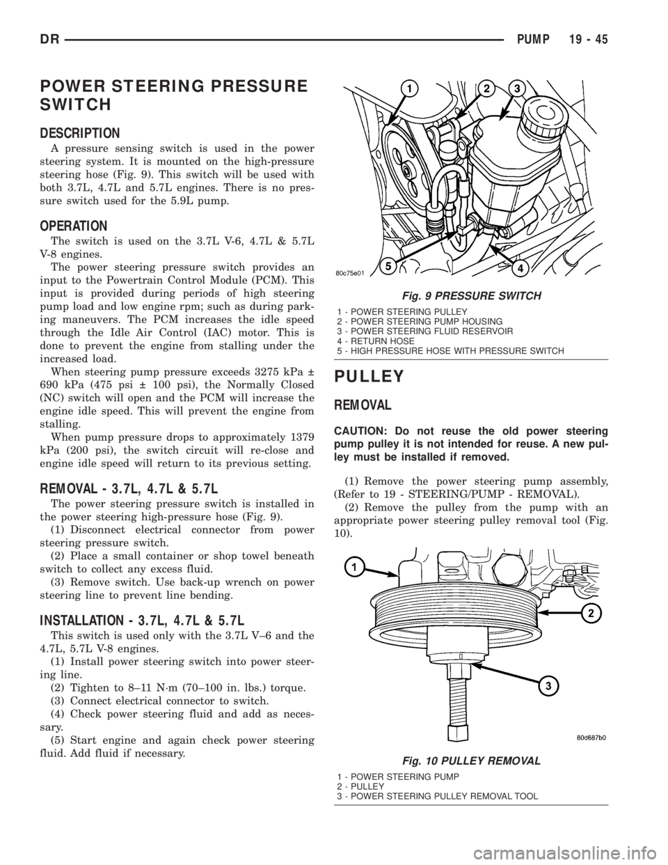
steering hose (Fig. 9). This switch will be used with
both 3.7L, 4.7L and 5.7L engines. There is no pres-
sure switch used for the 5.9L pump.
OPERATION
The switch is used on the 3.7L V-6, 4.7L & 5.7L
V-8 engines.
The power steering pressure switch provides an
input to the Powertrain Control Module (PCM). This
input is provided during periods of high steering
pump load and low engine rpm; such as during park-
ing maneuvers. The PCM increases the idle speed
through the Idle Air Control (IAC) motor. This is
done to prevent the engine from stalling under the
increased load.
When steering pump pressure exceeds 3275 kPa
690 kPa (475 psi 100 psi), the Normally Closed
(NC) switch will open and the PCM will increase the
engine idle speed. This will prevent the engine from
stalling.
When pump pressure drops to approximately 1379
kPa (200 psi), the switch circuit will re-close and
engine idle speed will return to its previous setting.
REMOVAL - 3.7L, 4.7L & 5.7L
The power steering pressure switch is installed in
the power steering high-pressure hose (Fig. 9).
(1) Disconnect electrical connector from power
steering pressure switch.
(2) Place a small container or shop towel beneath
switch to collect any excess fluid.
(3) Remove switch. Use back-up wrench on power
steering line to prevent line bending.
INSTALLATION - 3.7L, 4.7L & 5.7L
This switch is used only with the 3.7L V±6 and the
4.7L, 5.7L V-8 engines.
(1) Install power steering switch into power steer-
ing line.
(2) Tighten to 8±11 N´m (70±100 in. lbs.) torque.
(3) Connect electrical connector to switch.
(4) Check power steering fluid and add as neces-
sary.
(5) Start engine and again check power steering
fluid. Add fluid if necessary.
PULLEY
REMOVAL
CAUTION: Do not reuse the old power steering
pump pulley it is not intended for reuse. A new pul-
ley must be installed if removed.
(1) Remove the power steering pump assembly,
(Refer to 19 - STEERING/PUMP - REMOVAL).
(2) Remove the pulley from the pump with an
appropriate power steering pulley removal tool (Fig.
10).
Fig. 9 PRESSURE SWITCH
1 - POWER STEERING PULLEY
2 - POWER STEERING PUMP HOUSING
3 - POWER STEERING FLUID RESERVOIR
4 - RETURN HOSE
5 - HIGH PRESSURE HOSE WITH PRESSURE SWITCH
Fig. 10 PULLEY REMOVAL
1 - POWER STEERING PUMP
2 - PULLEY
3 - POWER STEERING PULLEY REMOVAL TOOL
DRPUMP 19 - 45
Page 1865 of 2895
(7) Install lock ball in dimple at front of shaft.
Hold ball in place with petroleum jelly if desired.
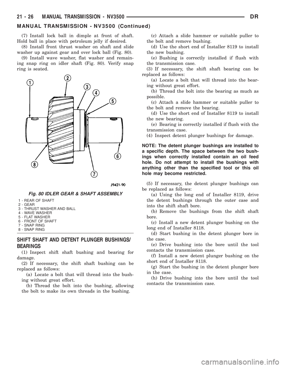
(8) Install front thrust washer on shaft and slide
washer up against gear and over lock ball (Fig. 80).
(9) Install wave washer, flat washer and remain-
ing snap ring on idler shaft (Fig. 80). Verify snap
ring is seated.
SHIFT SHAFT AND DETENT PLUNGER BUSHINGS/
BEARINGS
(1) Inspect shift shaft bushing and bearing for
damage.
(2) If necessary, the shift shaft bushing can be
replaced as follows:
(a) Locate a bolt that will thread into the bush-
ing without great effort.
(b) Thread the bolt into the bushing, allowing
the bolt to make its own threads in the bushing.(c) Attach a slide hammer or suitable puller to
the bolt and remove bushing.
(d) Use the short end of Installer 8119 to install
the new bushing.
(e) Bushing is correctly installed if flush with
the transmission case.
(3) If necessary, the shift shaft bearing can be
replaced as follows:
(a) Locate a bolt that will thread into the bear-
ing without great effort.
(b) Thread the bolt into the bearing as much as
possible.
(c) Attach a slide hammer or suitable puller to
the bolt and remove the bearing.
(d) Use the short end of Installer 8119 to install
the new bearing.
(e) Bearing is correctly installed if flush with the
transmission case.
(4) Inspect detent plunger bushings for damage.
NOTE: The detent plunger bushings are installed to
a specific depth. The space between the two bush-
ings when correctly installed contain an oil feed
hole. Do not attempt to install the bushings with
anything other than the specified tool or this oil
hole may become restricted.
(5) If necessary, the detent plunger bushings can
be replaced as follows:
(a) Using the long end of Installer 8119, drive
the detent bushings through the outer case and
into the shift shaft bore.
(b) Remove the bushings from the shift shaft
bore.
(c) Install a new detent plunger bushing on the
long end of Installer 8118.
(d) Start bushing in the detent plunger bore in
the case.
(e) Drive bushing into the bore until the tool
contacts the transmission case.
(f) Install a new detent plunger bushing on the
short end of Installer 8118.
(g) Start the bushing in the detent plunger bore
in the case.
(h) Drive bushing into the bore until the tool
contacts the transmission case.
Fig. 80 IDLER GEAR & SHAFT ASSEMBLY
1 - REAR OF SHAFT
2 - GEAR
3 - THRUST WASHER AND BALL
4 - WAVE WASHER
5 - FLAT WASHER
6 - FRONT OF SHAFT
7 - SNAP RING
8 - SNAP RING
21 - 26 MANUAL TRANSMISSION - NV3500DR
MANUAL TRANSMISSION - NV3500 (Continued)
Page 1891 of 2895
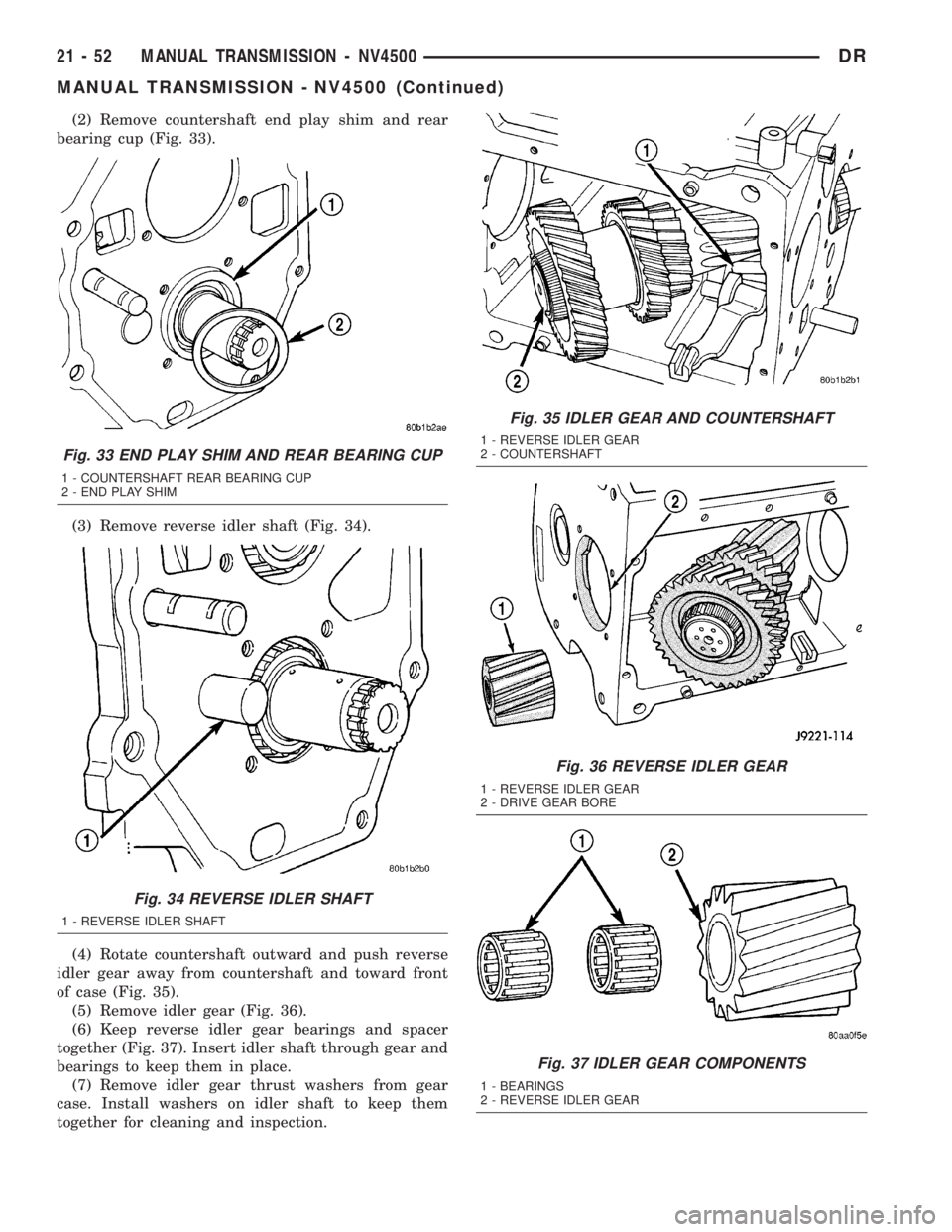
(2) Remove countershaft end play shim and rear
bearing cup (Fig. 33).
(3) Remove reverse idler shaft (Fig. 34).
(4) Rotate countershaft outward and push reverse
idler gear away from countershaft and toward front
of case (Fig. 35).
(5) Remove idler gear (Fig. 36).
(6) Keep reverse idler gear bearings and spacer
together (Fig. 37). Insert idler shaft through gear and
bearings to keep them in place.
(7) Remove idler gear thrust washers from gear
case. Install washers on idler shaft to keep them
together for cleaning and inspection.
Fig. 33 END PLAY SHIM AND REAR BEARING CUP
1 - COUNTERSHAFT REAR BEARING CUP
2 - END PLAY SHIM
Fig. 34 REVERSE IDLER SHAFT
1 - REVERSE IDLER SHAFT
Fig. 35 IDLER GEAR AND COUNTERSHAFT
1 - REVERSE IDLER GEAR
2 - COUNTERSHAFT
Fig. 36 REVERSE IDLER GEAR
1 - REVERSE IDLER GEAR
2 - DRIVE GEAR BORE
Fig. 37 IDLER GEAR COMPONENTS
1 - BEARINGS
2 - REVERSE IDLER GEAR
21 - 52 MANUAL TRANSMISSION - NV4500DR
MANUAL TRANSMISSION - NV4500 (Continued)
Page 1899 of 2895
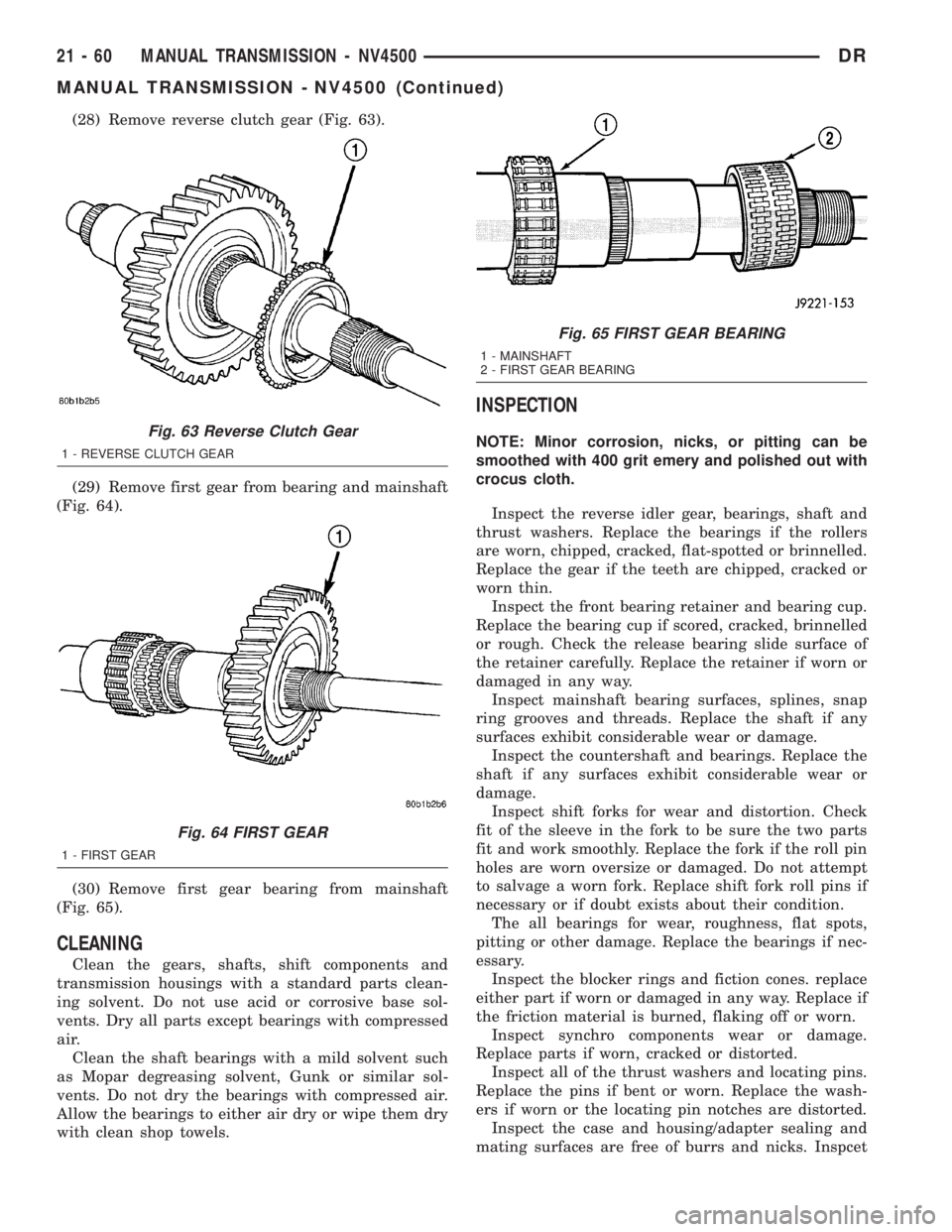
(28) Remove reverse clutch gear (Fig. 63).
(29) Remove first gear from bearing and mainshaft
(Fig. 64).
(30) Remove first gear bearing from mainshaft
(Fig. 65).
CLEANING
Clean the gears, shafts, shift components and
transmission housings with a standard parts clean-
ing solvent. Do not use acid or corrosive base sol-
vents. Dry all parts except bearings with compressed
air.
Clean the shaft bearings with a mild solvent such
as Mopar degreasing solvent, Gunk or similar sol-
vents. Do not dry the bearings with compressed air.
Allow the bearings to either air dry or wipe them dry
with clean shop towels.
INSPECTION
NOTE: Minor corrosion, nicks, or pitting can be
smoothed with 400 grit emery and polished out with
crocus cloth.
Inspect the reverse idler gear, bearings, shaft and
thrust washers. Replace the bearings if the rollers
are worn, chipped, cracked, flat-spotted or brinnelled.
Replace the gear if the teeth are chipped, cracked or
worn thin.
Inspect the front bearing retainer and bearing cup.
Replace the bearing cup if scored, cracked, brinnelled
or rough. Check the release bearing slide surface of
the retainer carefully. Replace the retainer if worn or
damaged in any way.
Inspect mainshaft bearing surfaces, splines, snap
ring grooves and threads. Replace the shaft if any
surfaces exhibit considerable wear or damage.
Inspect the countershaft and bearings. Replace the
shaft if any surfaces exhibit considerable wear or
damage.
Inspect shift forks for wear and distortion. Check
fit of the sleeve in the fork to be sure the two parts
fit and work smoothly. Replace the fork if the roll pin
holes are worn oversize or damaged. Do not attempt
to salvage a worn fork. Replace shift fork roll pins if
necessary or if doubt exists about their condition.
The all bearings for wear, roughness, flat spots,
pitting or other damage. Replace the bearings if nec-
essary.
Inspect the blocker rings and fiction cones. replace
either part if worn or damaged in any way. Replace if
the friction material is burned, flaking off or worn.
Inspect synchro components wear or damage.
Replace parts if worn, cracked or distorted.
Inspect all of the thrust washers and locating pins.
Replace the pins if bent or worn. Replace the wash-
ers if worn or the locating pin notches are distorted.
Inspect the case and housing/adapter sealing and
mating surfaces are free of burrs and nicks. InspcetFig. 63 Reverse Clutch Gear
1 - REVERSE CLUTCH GEAR
Fig. 64 FIRST GEAR
1 - FIRST GEAR
Fig. 65 FIRST GEAR BEARING
1 - MAINSHAFT
2 - FIRST GEAR BEARING
21 - 60 MANUAL TRANSMISSION - NV4500DR
MANUAL TRANSMISSION - NV4500 (Continued)