2003 DODGE RAM Output speed sensor
[x] Cancel search: Output speed sensorPage 1173 of 2895
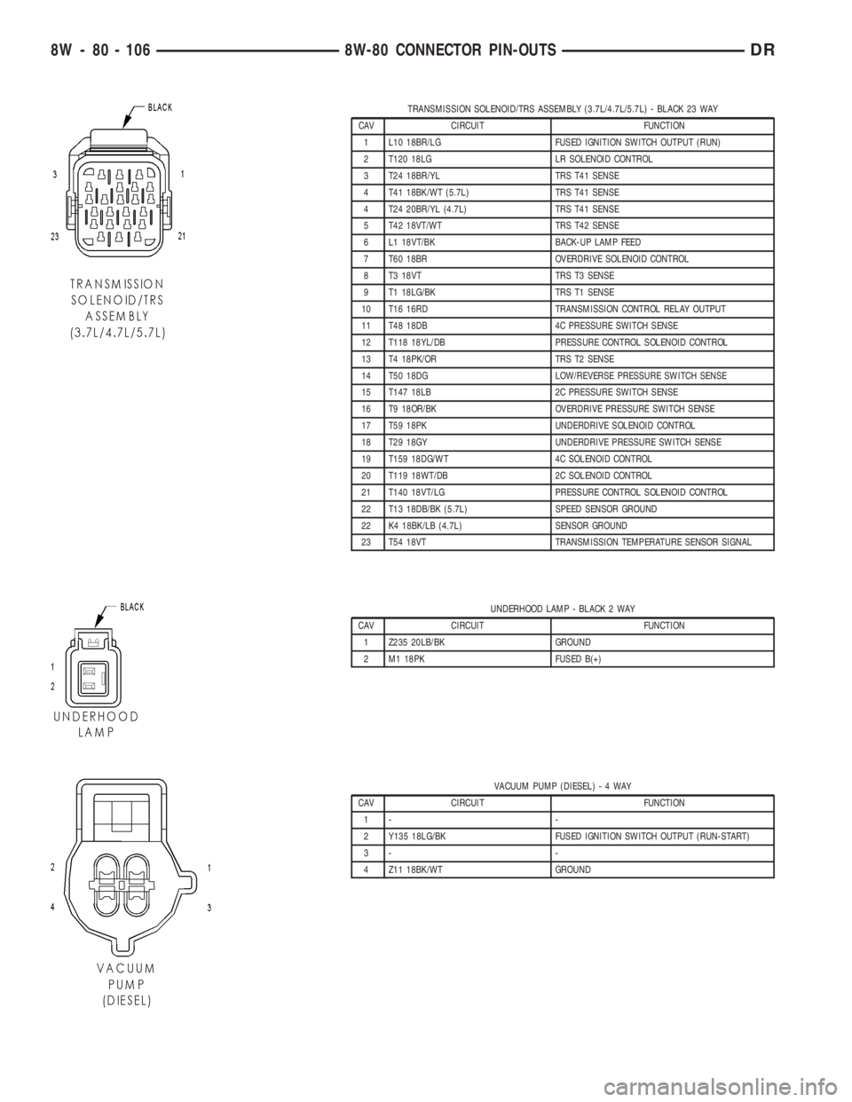
TRANSMISSION SOLENOID/TRS ASSEMBLY (3.7L/4.7L/5.7L) - BLACK 23 WAY
CAV CIRCUIT FUNCTION
1 L10 18BR/LG FUSED IGNITION SWITCH OUTPUT (RUN)
2 T120 18LG LR SOLENOID CONTROL
3 T24 18BR/YL TRS T41 SENSE
4 T41 18BK/WT (5.7L) TRS T41 SENSE
4 T24 20BR/YL (4.7L) TRS T41 SENSE
5 T42 18VT/WT TRS T42 SENSE
6 L1 18VT/BK BACK-UP LAMP FEED
7 T60 18BR OVERDRIVE SOLENOID CONTROL
8 T3 18VT TRS T3 SENSE
9 T1 18LG/BK TRS T1 SENSE
10 T16 16RD TRANSMISSION CONTROL RELAY OUTPUT
11 T48 18DB 4C PRESSURE SWITCH SENSE
12 T118 18YL/DB PRESSURE CONTROL SOLENOID CONTROL
13 T4 18PK/OR TRS T2 SENSE
14 T50 18DG LOW/REVERSE PRESSURE SWITCH SENSE
15 T147 18LB 2C PRESSURE SWITCH SENSE
16 T9 18OR/BK OVERDRIVE PRESSURE SWITCH SENSE
17 T59 18PK UNDERDRIVE SOLENOID CONTROL
18 T29 18GY UNDERDRIVE PRESSURE SWITCH SENSE
19 T159 18DG/WT 4C SOLENOID CONTROL
20 T119 18WT/DB 2C SOLENOID CONTROL
21 T140 18VT/LG PRESSURE CONTROL SOLENOID CONTROL
22 T13 18DB/BK (5.7L) SPEED SENSOR GROUND
22 K4 18BK/LB (4.7L) SENSOR GROUND
23 T54 18VT TRANSMISSION TEMPERATURE SENSOR SIGNAL
UNDERHOOD LAMP - BLACK 2 WAY
CAV CIRCUIT FUNCTION
1 Z235 20LB/BK GROUND
2 M1 18PK FUSED B(+)
VACUUM PUMP (DIESEL)-4WAY
CAV CIRCUIT FUNCTION
1- -
2 Y135 18LG/BK FUSED IGNITION SWITCH OUTPUT (RUN-START)
3- -
4 Z11 18BK/WT GROUND
8W - 80 - 106 8W-80 CONNECTOR PIN-OUTSDR
Page 1174 of 2895
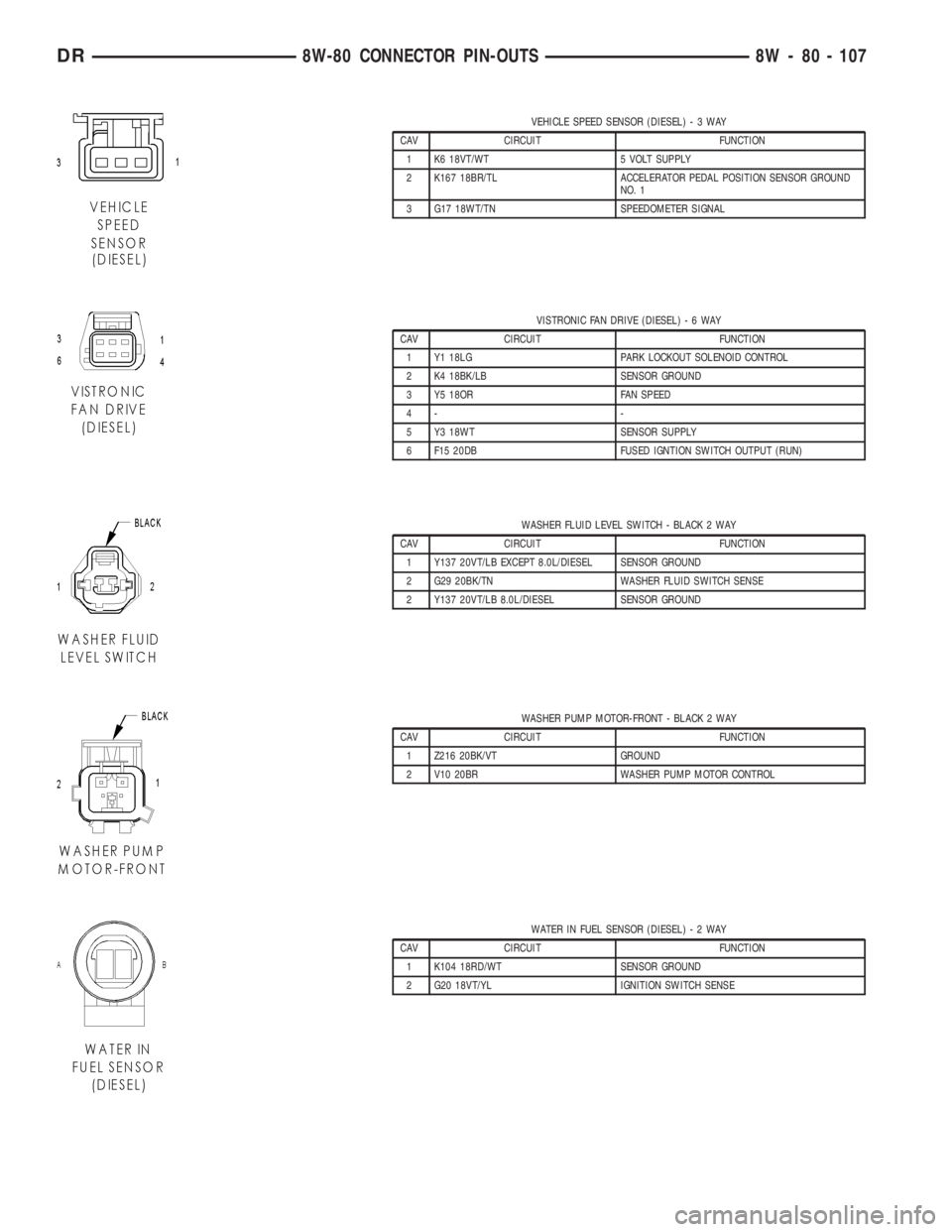
VEHICLE SPEED SENSOR (DIESEL)-3WAY
CAV CIRCUIT FUNCTION
1 K6 18VT/WT 5 VOLT SUPPLY
2 K167 18BR/TL ACCELERATOR PEDAL POSITION SENSOR GROUND
NO. 1
3 G17 18WT/TN SPEEDOMETER SIGNAL
VISTRONIC FAN DRIVE (DIESEL)-6WAY
CAV CIRCUIT FUNCTION
1 Y1 18LG PARK LOCKOUT SOLENOID CONTROL
2 K4 18BK/LB SENSOR GROUND
3 Y5 18OR FAN SPEED
4- -
5 Y3 18WT SENSOR SUPPLY
6 F15 20DB FUSED IGNTION SWITCH OUTPUT (RUN)
WASHER FLUID LEVEL SWITCH - BLACK 2 WAY
CAV CIRCUIT FUNCTION
1 Y137 20VT/LB EXCEPT 8.0L/DIESEL SENSOR GROUND
2 G29 20BK/TN WASHER FLUID SWITCH SENSE
2 Y137 20VT/LB 8.0L/DIESEL SENSOR GROUND
WASHER PUMP MOTOR-FRONT - BLACK 2 WAY
CAV CIRCUIT FUNCTION
1 Z216 20BK/VT GROUND
2 V10 20BR WASHER PUMP MOTOR CONTROL
WATER IN FUEL SENSOR (DIESEL)-2WAY
CAV CIRCUIT FUNCTION
1 K104 18RD/WT SENSOR GROUND
2 G20 18VT/YL IGNITION SWITCH SENSE
DR8W-80 CONNECTOR PIN-OUTS 8W - 80 - 107
Page 1175 of 2895
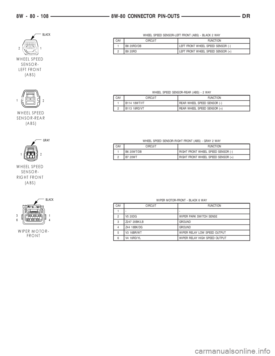
WHEEL SPEED SENSOR-LEFT FRONT (ABS) - BLACK 2 WAY
CAV CIRCUIT FUNCTION
1 B8 20RD/DB LEFT FRONT WHEEL SPEED SENSOR (-)
2 B9 20RD LEFT FRONT WHEEL SPEED SENSOR (+)
WHEEL SPEED SENSOR-REAR (ABS)-2WAY
CAV CIRCUIT FUNCTION
1 B114 18WT/VT REAR WHEEL SPEED SENSOR (-)
2 B113 18RD/VT REAR WHEEL SPEED SENSOR (+)
WHEEL SPEED SENSOR-RIGHT FRONT (ABS) - GRAY 2 WAY
CAV CIRCUIT FUNCTION
1 B6 20WT/DB RIGHT FRONT WHEEL SPEED SENSOR (-)
2 B7 20WT RIGHT FRONT WHEEL SPEED SENSOR (+)
WIPER MOTOR-FRONT - BLACK 6 WAY
CAV CIRCUIT FUNCTION
1- -
2 V5 20DG WIPER PARK SWITCH SENSE
3 Z247 20BK/LB GROUND
4 Z44 18BK/DG GROUND
5 V3 16BR/WT WIPER RELAY LOW SPEED OUTPUT
6 V4 16RD/YL WIPER RELAY HIGH SPEED OUTPUT
8W - 80 - 108 8W-80 CONNECTOR PIN-OUTSDR
Page 1177 of 2895
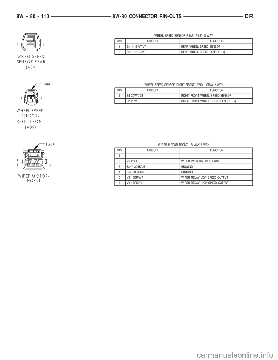
WHEEL SPEED SENSOR-REAR (ABS)- 2 WAY
CAV CIRCUIT FUNCTION
1 B114 18WT/VT REAR WHEEL SPEED SENSOR (-)
2 B113 18RD/VT REAR WHEEL SPEED SENSOR (+)
WHEEL SPEED SENSOR-RIGHT FRONT (ABS) - GRAY 2 WAY
CAV CIRCUIT FUNCTION
1 B6 20WT/DB RIGHT FRONT WHEEL SPEED SENSOR (-)
2 B7 20WT RIGHT FRONT WHEEL SPEED SENSOR (+)
WIPER MOTOR-FRONT - BLACK 6 WAY
CAV CIRCUIT FUNCTION
1- -
2 V5 20DG WIPER PARK SWITCH SENSE
3 Z247 20BK/LB GROUND
4 Z44 18BK/DG GROUND
5 V3 16BR/WT WIPER RELAY LOW SPEED OUTPUT
6 V4 16RD/YL WIPER RELAY HIGH SPEED OUTPUT
8W - 80 - 110 8W-80 CONNECTOR PIN-OUTSDR
Page 1183 of 2895
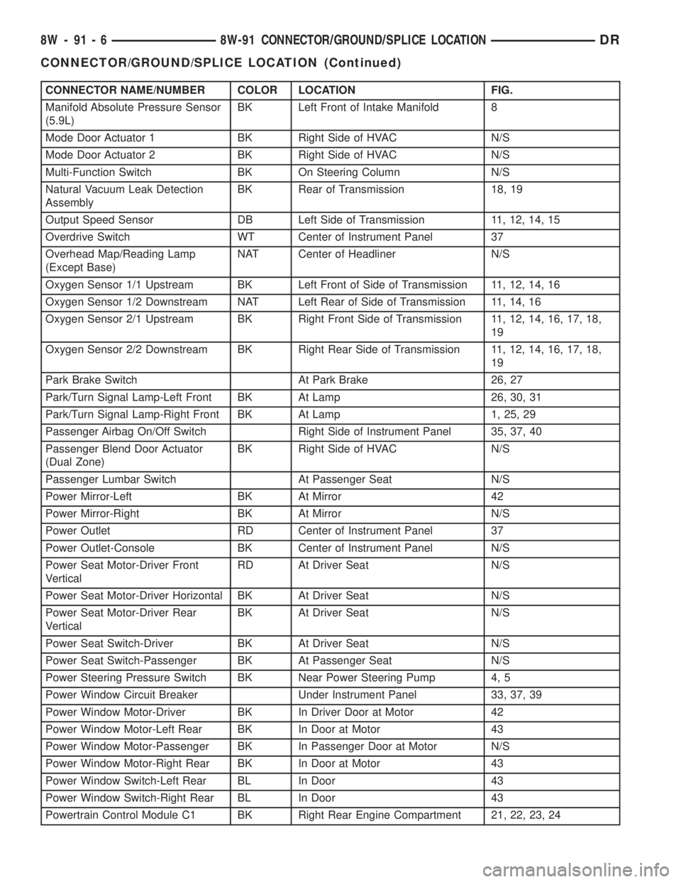
CONNECTOR NAME/NUMBER COLOR LOCATION FIG.
Manifold Absolute Pressure Sensor
(5.9L)BK Left Front of Intake Manifold 8
Mode Door Actuator 1 BK Right Side of HVAC N/S
Mode Door Actuator 2 BK Right Side of HVAC N/S
Multi-Function Switch BK On Steering Column N/S
Natural Vacuum Leak Detection
AssemblyBK Rear of Transmission 18, 19
Output Speed Sensor DB Left Side of Transmission 11, 12, 14, 15
Overdrive Switch WT Center of Instrument Panel 37
Overhead Map/Reading Lamp
(Except Base)NAT Center of Headliner N/S
Oxygen Sensor 1/1 Upstream BK Left Front of Side of Transmission 11, 12, 14, 16
Oxygen Sensor 1/2 Downstream NAT Left Rear of Side of Transmission 11, 14, 16
Oxygen Sensor 2/1 Upstream BK Right Front Side of Transmission 11, 12, 14, 16, 17, 18,
19
Oxygen Sensor 2/2 Downstream BK Right Rear Side of Transmission 11, 12, 14, 16, 17, 18,
19
Park Brake Switch At Park Brake 26, 27
Park/Turn Signal Lamp-Left Front BK At Lamp 26, 30, 31
Park/Turn Signal Lamp-Right Front BK At Lamp 1, 25, 29
Passenger Airbag On/Off Switch Right Side of Instrument Panel 35, 37, 40
Passenger Blend Door Actuator
(Dual Zone)BK Right Side of HVAC N/S
Passenger Lumbar Switch At Passenger Seat N/S
Power Mirror-Left BK At Mirror 42
Power Mirror-Right BK At Mirror N/S
Power Outlet RD Center of Instrument Panel 37
Power Outlet-Console BK Center of Instrument Panel N/S
Power Seat Motor-Driver Front
VerticalRD At Driver Seat N/S
Power Seat Motor-Driver Horizontal BK At Driver Seat N/S
Power Seat Motor-Driver Rear
VerticalBK At Driver Seat N/S
Power Seat Switch-Driver BK At Driver Seat N/S
Power Seat Switch-Passenger BK At Passenger Seat N/S
Power Steering Pressure Switch BK Near Power Steering Pump 4, 5
Power Window Circuit Breaker Under Instrument Panel 33, 37, 39
Power Window Motor-Driver BK In Driver Door at Motor 42
Power Window Motor-Left Rear BK In Door at Motor 43
Power Window Motor-Passenger BK In Passenger Door at Motor N/S
Power Window Motor-Right Rear BK In Door at Motor 43
Power Window Switch-Left Rear BL In Door 43
Power Window Switch-Right Rear BL In Door 43
Powertrain Control Module C1 BK Right Rear Engine Compartment 21, 22, 23, 24
8W - 91 - 6 8W-91 CONNECTOR/GROUND/SPLICE LOCATIONDR
CONNECTOR/GROUND/SPLICE LOCATION (Continued)
Page 1736 of 2895
(1) Install sensor to intake manifold. Tighten to
12±15 N´m (110±130 in. lbs.) torque.
(2) Install electrical connector.
MAP SENSOR
DESCRIPTION
3.7L V-6
The Manifold Absolute Pressure (MAP) sensor is
mounted into the front of the intake manifold with 2
screws.
4.7L V-8
The Manifold Absolute Pressure (MAP) sensor is
mounted into the front of the intake manifold with 2
screws.
5.7L V-8
The Manifold Absolute Pressure (MAP) sensor is
mounted to the front of the intake manifold air ple-
num box.
5.9L V-8
The Manifold Absolute Pressure (MAP) sensor is
mounted to the front of the throttle body with 2
screws.
8.0L V-10
The Manifold Absolute Pressure (MAP) sensor is
mounted into the right side of the intake manifold.
OPERATION
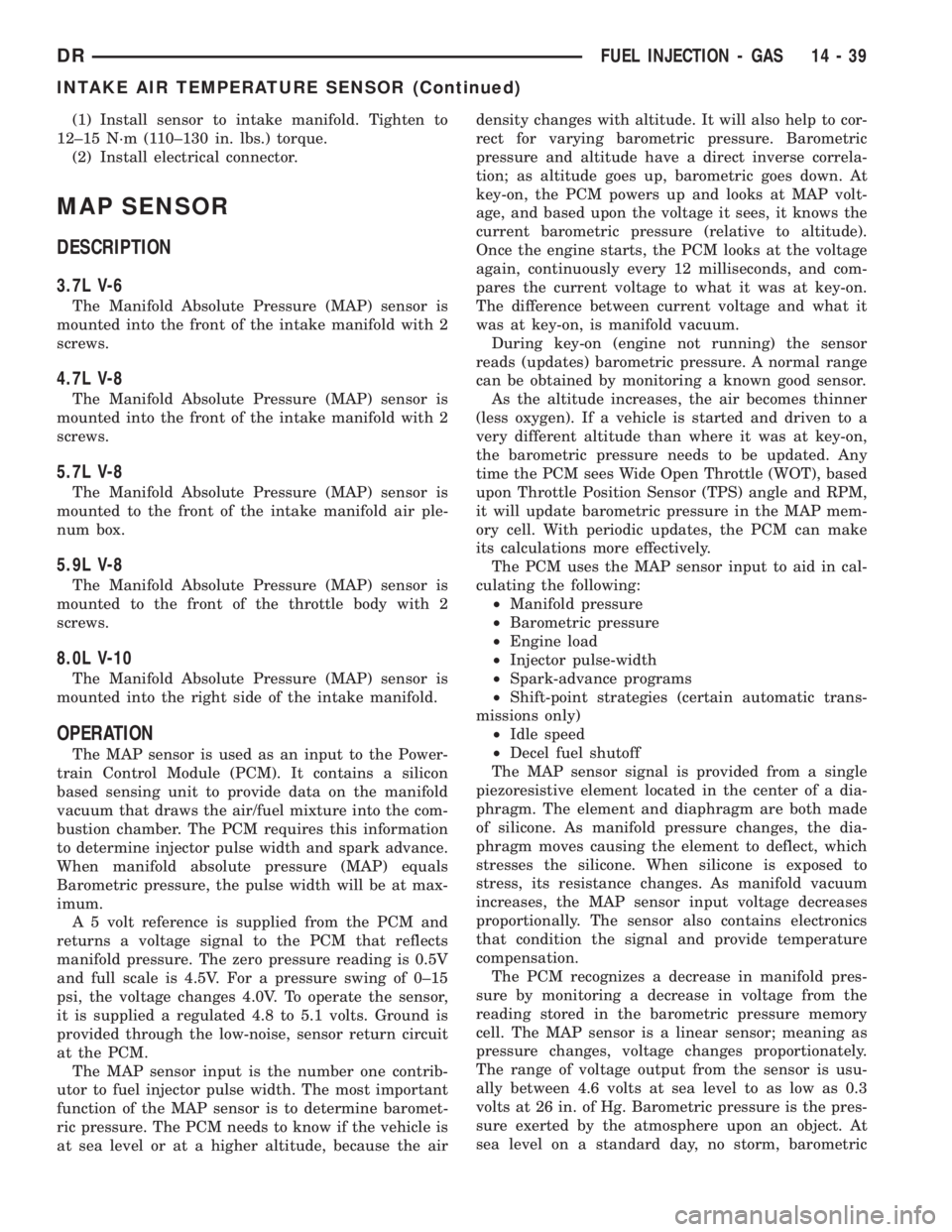
The MAP sensor is used as an input to the Power-
train Control Module (PCM). It contains a silicon
based sensing unit to provide data on the manifold
vacuum that draws the air/fuel mixture into the com-
bustion chamber. The PCM requires this information
to determine injector pulse width and spark advance.
When manifold absolute pressure (MAP) equals
Barometric pressure, the pulse width will be at max-
imum.
A 5 volt reference is supplied from the PCM and
returns a voltage signal to the PCM that reflects
manifold pressure. The zero pressure reading is 0.5V
and full scale is 4.5V. For a pressure swing of 0±15
psi, the voltage changes 4.0V. To operate the sensor,
it is supplied a regulated 4.8 to 5.1 volts. Ground is
provided through the low-noise, sensor return circuit
at the PCM.
The MAP sensor input is the number one contrib-
utor to fuel injector pulse width. The most important
function of the MAP sensor is to determine baromet-
ric pressure. The PCM needs to know if the vehicle is
at sea level or at a higher altitude, because the airdensity changes with altitude. It will also help to cor-
rect for varying barometric pressure. Barometric
pressure and altitude have a direct inverse correla-
tion; as altitude goes up, barometric goes down. At
key-on, the PCM powers up and looks at MAP volt-
age, and based upon the voltage it sees, it knows the
current barometric pressure (relative to altitude).
Once the engine starts, the PCM looks at the voltage
again, continuously every 12 milliseconds, and com-
pares the current voltage to what it was at key-on.
The difference between current voltage and what it
was at key-on, is manifold vacuum.
During key-on (engine not running) the sensor
reads (updates) barometric pressure. A normal range
can be obtained by monitoring a known good sensor.
As the altitude increases, the air becomes thinner
(less oxygen). If a vehicle is started and driven to a
very different altitude than where it was at key-on,
the barometric pressure needs to be updated. Any
time the PCM sees Wide Open Throttle (WOT), based
upon Throttle Position Sensor (TPS) angle and RPM,
it will update barometric pressure in the MAP mem-
ory cell. With periodic updates, the PCM can make
its calculations more effectively.
The PCM uses the MAP sensor input to aid in cal-
culating the following:
²Manifold pressure
²Barometric pressure
²Engine load
²Injector pulse-width
²Spark-advance programs
²Shift-point strategies (certain automatic trans-
missions only)
²Idle speed
²Decel fuel shutoff
The MAP sensor signal is provided from a single
piezoresistive element located in the center of a dia-
phragm. The element and diaphragm are both made
of silicone. As manifold pressure changes, the dia-
phragm moves causing the element to deflect, which
stresses the silicone. When silicone is exposed to
stress, its resistance changes. As manifold vacuum
increases, the MAP sensor input voltage decreases
proportionally. The sensor also contains electronics
that condition the signal and provide temperature
compensation.
The PCM recognizes a decrease in manifold pres-
sure by monitoring a decrease in voltage from the
reading stored in the barometric pressure memory
cell. The MAP sensor is a linear sensor; meaning as
pressure changes, voltage changes proportionately.
The range of voltage output from the sensor is usu-
ally between 4.6 volts at sea level to as low as 0.3
volts at 26 in. of Hg. Barometric pressure is the pres-
sure exerted by the atmosphere upon an object. At
sea level on a standard day, no storm, barometric
DRFUEL INJECTION - GAS 14 - 39
INTAKE AIR TEMPERATURE SENSOR (Continued)
Page 1740 of 2895
OXYGEN SENSOR
DESCRIPTION
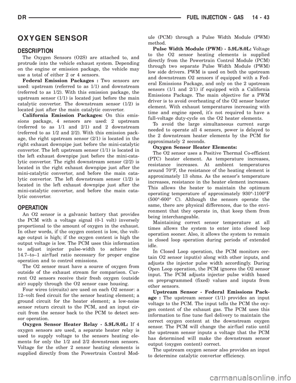
The Oxygen Sensors (O2S) are attached to, and
protrude into the vehicle exhaust system. Depending
on the engine or emission package, the vehicle may
use a total of either 2 or 4 sensors.
Federal Emission Packages :Two sensors are
used: upstream (referred to as 1/1) and downstream
(referred to as 1/2). With this emission package, the
upstream sensor (1/1) is located just before the main
catalytic convertor. The downstream sensor (1/2) is
located just after the main catalytic convertor.
California Emission Packages:On this emis-
sions package, 4 sensors are used: 2 upstream
(referred to as 1/1 and 2/1) and 2 downstream
(referred to as 1/2 and 2/2). With this emission pack-
age, the right upstream sensor (2/1) is located in the
right exhaust downpipe just before the mini-catalytic
convertor. The left upstream sensor (1/1) is located in
the left exhaust downpipe just before the mini-cata-
lytic convertor. The right downstream sensor (2/2) is
located in the right exhaust downpipe just after the
mini-catalytic convertor, and before the main cata-
lytic convertor. The left downstream sensor (1/2) is
located in the left exhaust downpipe just after the
mini-catalytic convertor, and before the main cata-
lytic convertor.
OPERATION
An O2 sensor is a galvanic battery that provides
the PCM with a voltage signal (0-1 volt) inversely
proportional to the amount of oxygen in the exhaust.
In other words, if the oxygen content is low, the volt-
age output is high; if the oxygen content is high the
output voltage is low. The PCM uses this information
to adjust injector pulse-width to achieve the
14.7±to±1 air/fuel ratio necessary for proper engine
operation and to control emissions.
The O2 sensor must have a source of oxygen from
outside of the exhaust stream for comparison. Cur-
rent O2 sensors receive their fresh oxygen (outside
air) supply through the O2 sensor case housing.
Four wires (circuits) are used on each O2 sensor: a
12±volt feed circuit for the sensor heating element; a
ground circuit for the heater element; a low-noise
sensor return circuit to the PCM, and an input cir-
cuit from the sensor back to the PCM to detect sen-
sor operation.
Oxygen Sensor Heater Relay - 5.9L/8.0L:If 4
oxygen sensors are used, a separate heater relay is
used to supply voltage to the sensors heating ele-
ments for only the 1/2 and 2/2 downstream sensors.
Voltage for the other 2 sensor heating elements is
supplied directly from the Powertrain Control Mod-ule (PCM) through a Pulse Width Module (PWM)
method.
Pulse Width Module (PWM) - 5.9L/8.0L:Voltage
to the O2 sensor heating elements is supplied
directly from the Powertrain Control Module (PCM)
through two separate Pulse Width Module (PWM)
low side drivers. PWM is used on both the upstream
and downstream O2 sensors if equipped with a Fed-
eral Emissions Package, and only on the 2 upstream
sensors (1/1 and 2/1) if equipped with a California
Emissions Package. The main objective for a PWM
driver is to avoid overheating of the O2 sensor heater
element. With exhaust temperatures increasing with
time and engine speed, it's not required to have a
full-voltage duty-cycle on the O2 heater elements.
To avoid the large simultaneous current surge
needed to operate all 4 sensors, power is delayed to
the 2 downstream heater elements by the PCM for
approximately 2 seconds.
Oxygen Sensor Heater Elements:
The O2 sensor uses a Positive Thermal Co-efficient
(PTC) heater element. As temperature increases,
resistance increases. At ambient temperatures
around 70ÉF, the resistance of the heating element is
approximately 13 ohms. As the sensor's temperature
increases, resistance in the heater element increases.
This allows the heater to maintain the optimum
operating temperature of approximately 930É-1100ÉF
(500É-600É C). Although the sensors operate the
same, there are physical differences, due to the envi-
ronment that they operate in, that keep them from
being interchangeable.
Maintaining correct sensor temperature at all
times allows the system to enter into closed loop
operation sooner. Also, it allows the system to remain
in closed loop operation during periods of extended
idle.
In Closed Loop operation, the PCM monitors cer-
tain O2 sensor input(s) along with other inputs, and
adjusts the injector pulse width accordingly. During
Open Loop operation, the PCM ignores the O2 sensor
input. The PCM adjusts injector pulse width based
on preprogrammed (fixed) values and inputs from
other sensors.
Upstream Sensor - Federal Emissions Pack-
age :The upstream sensor (1/1) provides an input
voltage to the PCM. The input tells the PCM the oxy-
gen content of the exhaust gas. The PCM uses this
information to fine tune fuel delivery to maintain the
correct oxygen content at the downstream oxygen
sensor. The PCM will change the air/fuel ratio until
the upstream sensor inputs a voltage that the PCM
has determined will make the downstream sensor
output (oxygen content) correct.
The upstream oxygen sensor also provides an input
to determine catalytic convertor efficiency.
DRFUEL INJECTION - GAS 14 - 43
Page 1969 of 2895
CLEANING...........................214
INSPECTION.........................214
ASSEMBLY...........................215
OUTPUT SHAFT FRONT BEARING
REMOVAL............................217
INSTALLATION........................217
OUTPUT SHAFT REAR BEARING
REMOVAL............................217
INSTALLATION........................217
OVERDRIVE CLUTCH
DESCRIPTION........................218
OPERATION..........................218
OVERDRIVE SWITCH
DESCRIPTION........................218
OPERATION..........................218
DIAGNOSIS AND TESTING - OVERDRIVE
ELECTRICAL CONTROLS..............219
REMOVAL............................219
INSTALLATION........................219
OVERDRIVE UNIT
REMOVAL............................220
DISASSEMBLY........................220
CLEANING...........................227
INSPECTION.........................227
ASSEMBLY...........................228
INSTALLATION........................236
OVERRUNNING CLUTCH CAM/OVERDRIVE
PISTON RETAINER
DESCRIPTION........................237
OPERATION..........................237
DISASSEMBLY........................238
CLEANING...........................238
INSPECTION.........................238
ASSEMBLY...........................239
PISTONS
DESCRIPTION........................241
OPERATION..........................241
PLANETARY GEARTRAIN/OUTPUT SHAFT
DESCRIPTION........................242
OPERATION..........................243
DISASSEMBLY........................243
INSPECTION.........................245
ASSEMBLY...........................245
REAR CLUTCH
DESCRIPTION........................248
OPERATION..........................249
DISASSEMBLY........................249
CLEANING...........................250
INSPECTION.........................250
ASSEMBLY...........................250REAR SERVO
DESCRIPTION........................252
OPERATION..........................252
DISASSEMBLY........................252
CLEANING...........................252
ASSEMBLY...........................253
SHIFT MECHANISM
DESCRIPTION........................253
OPERATION..........................253
SOLENOID
DESCRIPTION........................253
OPERATION..........................254
SPEED SENSOR
DESCRIPTION........................254
OPERATION..........................254
THROTTLE VALVE CABLE
DESCRIPTION........................254
ADJUSTMENTS - THROTTLE VALVE
CABLE.............................255
TORQUE CONVERTER
DESCRIPTION........................257
OPERATION..........................261
REMOVAL............................262
INSTALLATION........................262
TORQUE CONVERTER DRAINBACK VALVE
DESCRIPTION........................262
OPERATION..........................262
STANDARD PROCEDURE - TORQUE
CONVERTER DRAINBACK VALVE........262
TRANSMISSION RANGE SENSOR
DESCRIPTION........................263
OPERATION..........................263
DIAGNOSIS AND TESTING - TRANSMISSION
RANGE SENSOR (TRS)................264
REMOVAL............................265
INSTALLATION........................266
TRANSMISSION TEMPERATURE SENSOR
DESCRIPTION........................267
OPERATION..........................267
VALVE BODY
DESCRIPTION........................267
OPERATION..........................272
REMOVAL............................286
DISASSEMBLY........................287
CLEANING...........................298
INSPECTION.........................298
ASSEMBLY...........................299
INSTALLATION........................307
ADJUSTMENTS - VALVE BODY...........308
21 - 130 AUTOMATIC TRANSMISSION - 46REDR