2003 DODGE RAM Output speed sensor
[x] Cancel search: Output speed sensorPage 2217 of 2895
GOVERNOR PRESSURE SENSOR
The sensor output signal provides the necessary
feedback to the PCM. This feedback is needed to ade-
quately control governor pressure.
GOVERNOR BODY AND TRANSFER PLATE
The transfer plate channels line pressure to the
solenoid valve through the governor body. It also
channels governor pressure from the solenoid valve
to the governor circuit. It is the solenoid valve that
develops the necessary governor pressure.
GOVERNOR PRESSURE CURVES
LOW TRANSMISSION FLUID TEMPERATURE
When the transmission fluid is cold the conven-
tional governor can delay shifts, resulting in higher
than normal shift speeds and harsh shifts. The elec-
tronically controlled low temperature governor pres-
sure curve is higher than normal to make the
transmission shift at normal speeds and sooner. The
PCM uses a temperature sensor in the transmission
oil sump to determine when low temperature gover-
nor pressure is needed.
NORMAL OPERATION
Normal operation is refined through the increased
computing power of the PCM and through access to
data on engine operating conditions provided by the
PCM that were not available with the previous
stand-alone electronic module. This facilitated the
development of a load adaptive shift strategy - the
ability to alter the shift schedule in response to vehi-
cle load condition. One manifestation of this capabil-
ity is grade9hunting9prevention - the ability of the
transmission logic to delay an upshift on a grade if
the engine does not have sufficient power to main-
tain speed in the higher gear. The 3-2 downshift and
the potential for hunting between gears occurs with a
heavily loaded vehicle or on steep grades. When
hunting occurs, it is very objectionable because shifts
are frequent and accompanied by large changes in
noise and acceleration.
WIDE OPEN THROTTLE OPERATION
In wide-open throttle (WOT) mode, adaptive mem-
ory in the PCM assures that up-shifts occur at the
preprogrammed optimum speed. WOT operation is
determined from the throttle position sensor, which
is also a part of the emission control system. The ini-tial setting for the WOT upshift is below the opti-
mum engine speed. As WOT shifts are repeated, the
PCM learns the time required to complete the shifts
by comparing the engine speed when the shifts occur
to the optimum speed. After each shift, the PCM
adjusts the shift point until the optimum speed is
reached. The PCM also considers vehicle loading,
grade and engine performance changes due to high
altitude in determining when to make WOT shifts. It
does this by measuring vehicle and engine accelera-
tion and then factoring in the shift time.
TRANSFER CASE LOW RANGE OPERATION
On four-wheel drive vehicles operating in low
range, the engine can accelerate to its peak more
rapidly than in Normal range, resulting in delayed
shifts and undesirable engine9flare.9The low range
governor pressure curve is also higher than normal
to initiate upshifts sooner. The PCM compares elec-
tronic vehicle speed signal used by the speedometer
to the transmission output shaft speed signal to
determine when the transfer case is in low range.
REMOVAL
(1) Hoist and support vehicle on safety stands.
(2) Remove transmission fluid pan and filter.
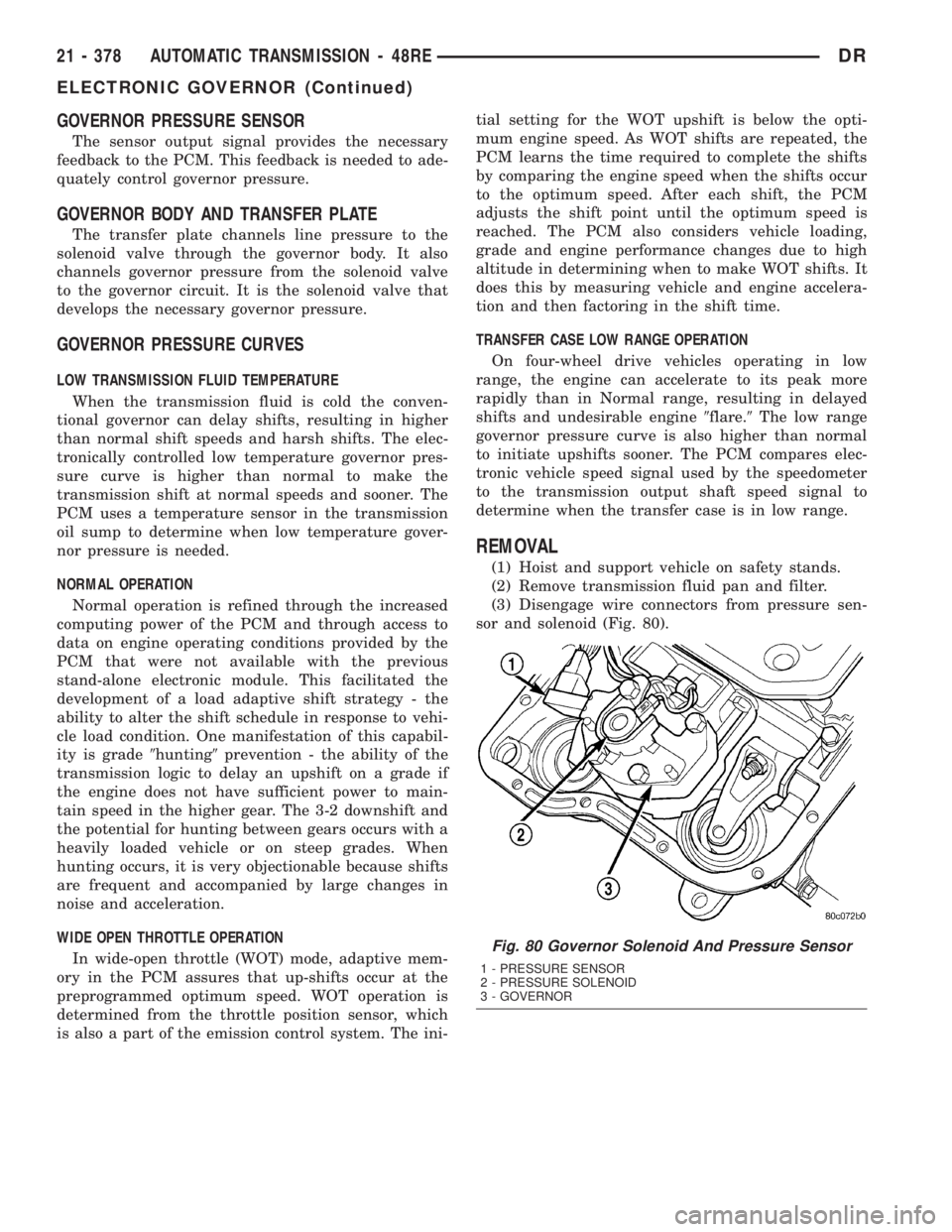
(3) Disengage wire connectors from pressure sen-
sor and solenoid (Fig. 80).
Fig. 80 Governor Solenoid And Pressure Sensor
1 - PRESSURE SENSOR
2 - PRESSURE SOLENOID
3 - GOVERNOR
21 - 378 AUTOMATIC TRANSMISSION - 48REDR
ELECTRONIC GOVERNOR (Continued)
Page 2252 of 2895
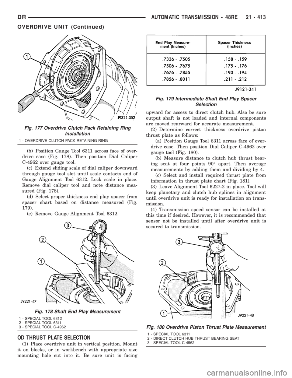
(b) Position Gauge Tool 6311 across face of over-
drive case (Fig. 178). Then position Dial Caliper
C-4962 over gauge tool.
(c) Extend sliding scale of dial caliper downward
through gauge tool slot until scale contacts end of
Gauge Alignment Tool 6312. Lock scale in place.
Remove dial caliper tool and note distance mea-
sured (Fig. 178).
(d) Select proper thickness end play spacer from
spacer chart based on distance measured (Fig.
179).
(e) Remove Gauge Alignment Tool 6312.
OD THRUST PLATE SELECTION
(1) Place overdrive unit in vertical position. Mount
it on blocks, or in workbench with appropriate size
mounting hole cut into it. Be sure unit is facingupward for access to direct clutch hub. Also be sure
output shaft is not loaded and internal components
are moved rearward for accurate measurement.
(2) Determine correct thickness overdrive piston
thrust plate as follows:
(a) Position Gauge Tool 6311 across face of over-
drive case. Then position Dial Caliper C-4962 over
gauge tool (Fig. 180).
(b) Measure distance to clutch hub thrust bear-
ing seat at four points 90É apart. Then average
measurements by adding them and dividing by 4.
(c) Select and install required thrust plate from
information in thrust plate chart (Fig. 181).
(3) Leave Alignment Tool 6227-2 in place. Tool will
keep planetary and clutch hub splines in alignment
until overdrive unit is ready for installation on trans-
mission.
(4) Transmission speed sensor can be installed at
this time if desired. However, it is recommended that
sensor not be installed until after overdrive unit is
secured to transmission.
Fig. 177 Overdrive Clutch Pack Retaining Ring
Installation
1 - OVERDRIVE CLUTCH PACK RETAINING RING
Fig. 178 Shaft End Play Measurement
1 - SPECIAL TOOL 6312
2 - SPECIAL TOOL 6311
3 - SPECIAL TOOL C-4962
Fig. 179 Intermediate Shaft End Play Spacer
Selection
Fig. 180 Overdrive Piston Thrust Plate Measurement
1 - SPECIAL TOOL 6311
2 - DIRECT CLUTCH HUB THRUST BEARING SEAT
3 - SPECIAL TOOL C-4962
DRAUTOMATIC TRANSMISSION - 48RE 21 - 413
OVERDRIVE UNIT (Continued)
Page 2270 of 2895
SOLENOID
DESCRIPTION
The typical electrical solenoid used in automotive
applications is a linear actuator. It is a device that
produces motion in a straight line. This straight line
motion can be either forward or backward in direc-
tion, and short or long distance.
A solenoid is an electromechanical device that uses
a magnetic force to perform work. It consists of a coil
of wire, wrapped around a magnetic core made from
steel or iron, and a spring loaded, movable plunger,
which performs the work, or straight line motion.
The solenoids used in transmission applications
are attached to valves which can be classified asnor-
mally openornormally closed. Thenormally
opensolenoid valve is defined as a valve which
allows hydraulic flow when no current or voltage is
applied to the solenoid. Thenormally closedsole-
noid valve is defined as a valve which does not allow
hydraulic flow when no current or voltage is applied
to the solenoid. These valves perform hydraulic con-
trol functions for the transmission and must there-
fore be durable and tolerant of dirt particles. For
these reasons, the valves have hardened steel pop-
pets and ball valves. The solenoids operate the valves
directly, which means that the solenoids must have
very high outputs to close the valves against the siz-
able flow areas and line pressures found in current
transmissions. Fast response time is also necessary
to ensure accurate control of the transmission.
The strength of the magnetic field is the primary
force that determines the speed of operation in a par-
ticular solenoid design. A stronger magnetic field will
cause the plunger to move at a greater speed than a
weaker one. There are basically two ways to increase
the force of the magnetic field:
1. Increase the amount of current applied to the
coil or
2. Increase the number of turns of wire in the coil.
The most common practice is to increase the num-
ber of turns by using thin wire that can completely
fill the available space within the solenoid housing.
The strength of the spring and the length of the
plunger also contribute to the response speed possi-
ble by a particular solenoid design.
A solenoid can also be described by the method by
which it is controlled. Some of the possibilities
include variable force, pulse-width modulated, con-
stant ON, or duty cycle. The variable force and pulse-
width modulated versions utilize similar methods to
control the current flow through the solenoid to posi-
tion the solenoid plunger at a desired position some-
where between full ON and full OFF. The constant
ON and duty cycled versions control the voltageacross the solenoid to allow either full flow or no flow
through the solenoid's valve.OPERATION
When an electrical current is applied to the sole-
noid coil, a magnetic field is created which produces
an attraction to the plunger, causing the plunger to
move and work against the spring pressure and the
load applied by the fluid the valve is controlling. The
plunger is normally directly attached to the valve
which it is to operate. When the current is removed
from the coil, the attraction is removed and the
plunger will return to its original position due to
spring pressure.
The plunger is made of a conductive material and
accomplishes this movement by providing a path for
the magnetic field to flow. By keeping the air gap
between the plunger and the coil to the minimum
necessary to allow free movement of the plunger, the
magnetic field is maximized.
SPEED SENSOR
DESCRIPTION
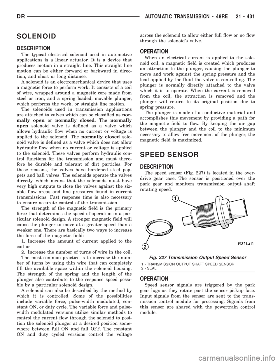
The speed sensor (Fig. 227) is located in the over-
drive gear case. The sensor is positioned over the
park gear and monitors transmission output shaft
rotating speed.
OPERATION
Speed sensor signals are triggered by the park
gear lugs as they rotate past the sensor pickup face.
Input signals from the sensor are sent to the trans-
mission control module for processing. Signals from
this sensor are shared with the powertrain control
module.
Fig. 227 Transmission Output Speed Sensor
1 - TRANSMISSION OUTPUT SHAFT SPEED SENSOR
2 - SEAL
DRAUTOMATIC TRANSMISSION - 48RE 21 - 431
Page 2328 of 2895
OIL PUMP FRONT SEAL
REMOVAL............................567
INSTALLATION........................567
OUTPUT SPEED SENSOR
DESCRIPTION........................567
OPERATION..........................567
REMOVAL............................567
INSTALLATION........................567
OVERDRIVE SWITCH
DESCRIPTION........................568
OPERATION..........................568
REMOVAL............................568
INSTALLATION........................569
PISTONS
DESCRIPTION........................569
OPERATION..........................569
PLANETARY GEARTRAIN
DESCRIPTION........................571
OPERATION..........................571
DISASSEMBLY........................573
CLEANING...........................573
INSPECTION.........................573
ASSEMBLY...........................573
SHIFT MECHANISM
DESCRIPTION........................574
OPERATION..........................574
SOLENOID SWITCH VALVE
DESCRIPTION........................574
OPERATION..........................574
SOLENOIDS
DESCRIPTION........................574OPERATION..........................575
TORQUE CONVERTER
DESCRIPTION........................575
OPERATION..........................579
REMOVAL............................580
INSTALLATION........................580
TRANSMISSION CONTROL RELAY
DESCRIPTION........................581
OPERATION..........................581
TRANSMISSION RANGE SENSOR
DESCRIPTION........................581
OPERATION..........................581
TRANSMISSION SOLENOID/TRS ASSEMBLY
DESCRIPTION........................582
OPERATION..........................582
REMOVAL............................583
INSTALLATION........................583
TRANSMISSION TEMPERATURE SENSOR
DESCRIPTION........................583
OPERATION..........................583
VALVE BODY
DESCRIPTION........................584
OPERATION..........................585
REMOVAL............................585
DISASSEMBLY........................586
CLEANING...........................588
INSPECTION.........................588
ASSEMBLY...........................590
INSTALLATION........................590
AUTOMATIC TRANSMISSION -
45RFE/545RFE
DESCRIPTION
The 45RFE/545RFE automatic transmissions is a
sophisticated, multi-range, electronically controlled
transmission which combines optimized gear ratios
for responsive performance, state of the art efficiency
features and low NVH. Other features include driver
adaptive shifting and three planetary gear sets to
provide wide ratio capability with precise ratio steps
for optimum driveability. The three planetary gear
sets also make available a unique alternate second
gear ratio. The primary 2nd gear ratio fits between
1st and 3rd gears for normal through-gear accelera-
tions. The alternate second gear ratio (2prime) allows
smoother 4-2 kickdowns at high speeds to provide
2nd gear passing performance over a wider highway
cruising range.
The hydraulic portion of the transmission consists
of the transmission fluid, fluid passages, hydraulic
valves, and various line pressure control components.The primary mechanical components of the trans-
mission consist of the following:
²Three multiple disc input clutches
²Three multiple disc holding clutches
²Five hydraulic accumulators
²Three planetary gear sets
²Dual Stage Hydraulic oil pump
²Valve body
²Solenoid pack
The TCM is the ªheartº or ªbrainº of the electronic
control system and relies on information from vari-
ous direct and indirect inputs (sensors, switches, etc.)
to determine driver demand and vehicle operating
conditions. With this information, the TCM can cal-
culate and perform timely and quality shifts through
various output or control devices (solenoid pack,
transmission control relay, etc.).
TRANSMISSION IDENTIFICATION
Transmission identification numbers are stamped
on the left side of the case just above the oil pan
sealing surface (Fig. 1). Refer to this information
when ordering replacement parts. A label is attached
to the transmission case above the stamped numbers.
DRAUTOMATIC TRANSMISSION - 45RFE/545RFE 21 - 489
Page 2329 of 2895
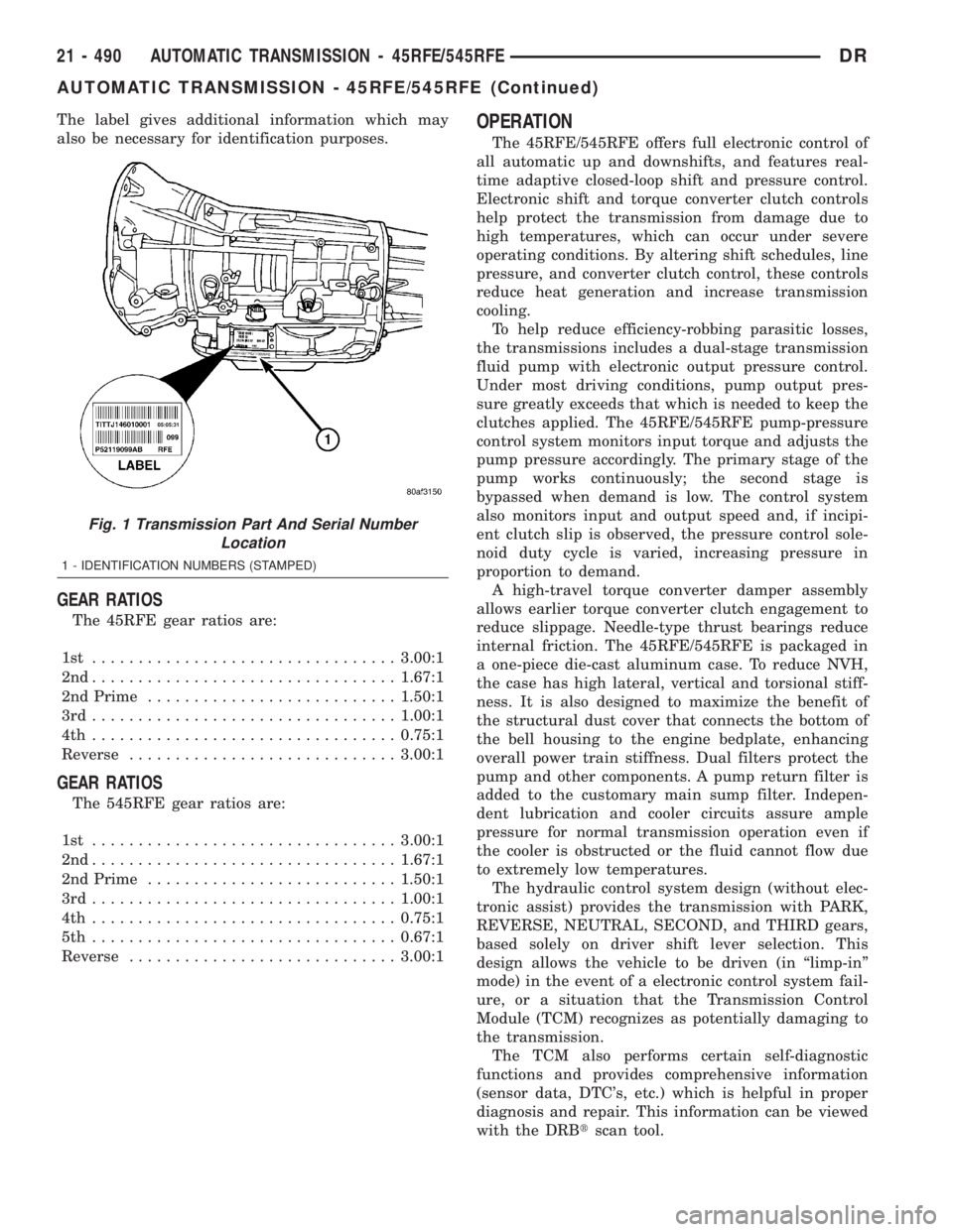
The label gives additional information which may
also be necessary for identification purposes.
GEAR RATIOS
The 45RFE gear ratios are:
1st .................................3.00:1
2nd.................................1.67:1
2nd Prime...........................1.50:1
3rd.................................1.00:1
4th .................................0.75:1
Reverse.............................3.00:1
GEAR RATIOS
The 545RFE gear ratios are:
1st .................................3.00:1
2nd.................................1.67:1
2nd Prime...........................1.50:1
3rd.................................1.00:1
4th .................................0.75:1
5th .................................0.67:1
Reverse.............................3.00:1
OPERATION
The 45RFE/545RFE offers full electronic control of
all automatic up and downshifts, and features real-
time adaptive closed-loop shift and pressure control.
Electronic shift and torque converter clutch controls
help protect the transmission from damage due to
high temperatures, which can occur under severe
operating conditions. By altering shift schedules, line
pressure, and converter clutch control, these controls
reduce heat generation and increase transmission
cooling.
To help reduce efficiency-robbing parasitic losses,
the transmissions includes a dual-stage transmission
fluid pump with electronic output pressure control.
Under most driving conditions, pump output pres-
sure greatly exceeds that which is needed to keep the
clutches applied. The 45RFE/545RFE pump-pressure
control system monitors input torque and adjusts the
pump pressure accordingly. The primary stage of the
pump works continuously; the second stage is
bypassed when demand is low. The control system
also monitors input and output speed and, if incipi-
ent clutch slip is observed, the pressure control sole-
noid duty cycle is varied, increasing pressure in
proportion to demand.
A high-travel torque converter damper assembly
allows earlier torque converter clutch engagement to
reduce slippage. Needle-type thrust bearings reduce
internal friction. The 45RFE/545RFE is packaged in
a one-piece die-cast aluminum case. To reduce NVH,
the case has high lateral, vertical and torsional stiff-
ness. It is also designed to maximize the benefit of
the structural dust cover that connects the bottom of
the bell housing to the engine bedplate, enhancing
overall power train stiffness. Dual filters protect the
pump and other components. A pump return filter is
added to the customary main sump filter. Indepen-
dent lubrication and cooler circuits assure ample
pressure for normal transmission operation even if
the cooler is obstructed or the fluid cannot flow due
to extremely low temperatures.
The hydraulic control system design (without elec-
tronic assist) provides the transmission with PARK,
REVERSE, NEUTRAL, SECOND, and THIRD gears,
based solely on driver shift lever selection. This
design allows the vehicle to be driven (in ªlimp-inº
mode) in the event of a electronic control system fail-
ure, or a situation that the Transmission Control
Module (TCM) recognizes as potentially damaging to
the transmission.
The TCM also performs certain self-diagnostic
functions and provides comprehensive information
(sensor data, DTC's, etc.) which is helpful in proper
diagnosis and repair. This information can be viewed
with the DRBtscan tool.
Fig. 1 Transmission Part And Serial Number
Location
1 - IDENTIFICATION NUMBERS (STAMPED)
21 - 490 AUTOMATIC TRANSMISSION - 45RFE/545RFEDR
AUTOMATIC TRANSMISSION - 45RFE/545RFE (Continued)
Page 2335 of 2895
(9) Disconnect and lower or remove any necessary
exhaust components.
(10) Remove the starter motor.
(11) Rotate crankshaft in clockwise direction until
converter bolts are accessible. Then remove bolts one
at a time. Rotate crankshaft with socket wrench on
dampener bolt.
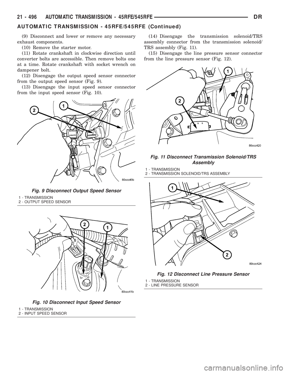
(12) Disengage the output speed sensor connector
from the output speed sensor (Fig. 9).
(13) Disengage the input speed sensor connector
from the input speed sensor (Fig. 10).(14) Disengage the transmission solenoid/TRS
assembly connector from the transmission solenoid/
TRS assembly (Fig. 11).
(15) Disengage the line pressure sensor connector
from the line pressure sensor (Fig. 12).
Fig. 9 Disconnect Output Speed Sensor
1 - TRANSMISSION
2 - OUTPUT SPEED SENSOR
Fig. 10 Disconnect Input Speed Sensor
1 - TRANSMISSION
2 - INPUT SPEED SENSOR
Fig. 11 Disconnect Transmission Solenoid/TRS
Assembly
1 - TRANSMISSION
2 - TRANSMISSION SOLENOID/TRS ASSEMBLY
Fig. 12 Disconnect Line Pressure Sensor
1 - TRANSMISSION
2 - LINE PRESSURE SENSOR
21 - 496 AUTOMATIC TRANSMISSION - 45RFE/545RFEDR
AUTOMATIC TRANSMISSION - 45RFE/545RFE (Continued)
Page 2336 of 2895
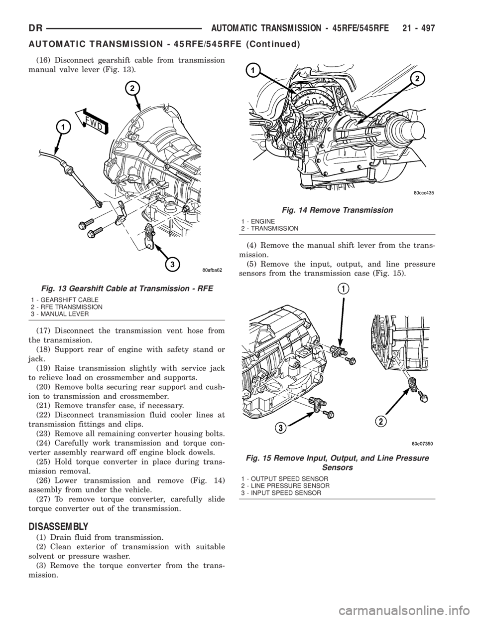
(16) Disconnect gearshift cable from transmission
manual valve lever (Fig. 13).
(17) Disconnect the transmission vent hose from
the transmission.
(18) Support rear of engine with safety stand or
jack.
(19) Raise transmission slightly with service jack
to relieve load on crossmember and supports.
(20) Remove bolts securing rear support and cush-
ion to transmission and crossmember.
(21) Remove transfer case, if necessary.
(22) Disconnect transmission fluid cooler lines at
transmission fittings and clips.
(23) Remove all remaining converter housing bolts.
(24) Carefully work transmission and torque con-
verter assembly rearward off engine block dowels.
(25) Hold torque converter in place during trans-
mission removal.
(26) Lower transmission and remove (Fig. 14)
assembly from under the vehicle.
(27) To remove torque converter, carefully slide
torque converter out of the transmission.
DISASSEMBLY
(1) Drain fluid from transmission.
(2) Clean exterior of transmission with suitable
solvent or pressure washer.
(3) Remove the torque converter from the trans-
mission.(4) Remove the manual shift lever from the trans-
mission.
(5) Remove the input, output, and line pressure
sensors from the transmission case (Fig. 15).
Fig. 13 Gearshift Cable at Transmission - RFE
1 - GEARSHIFT CABLE
2 - RFE TRANSMISSION
3 - MANUAL LEVER
Fig. 14 Remove Transmission
1 - ENGINE
2 - TRANSMISSION
Fig. 15 Remove Input, Output, and Line Pressure
Sensors
1 - OUTPUT SPEED SENSOR
2 - LINE PRESSURE SENSOR
3 - INPUT SPEED SENSOR
DRAUTOMATIC TRANSMISSION - 45RFE/545RFE 21 - 497
AUTOMATIC TRANSMISSION - 45RFE/545RFE (Continued)
Page 2346 of 2895
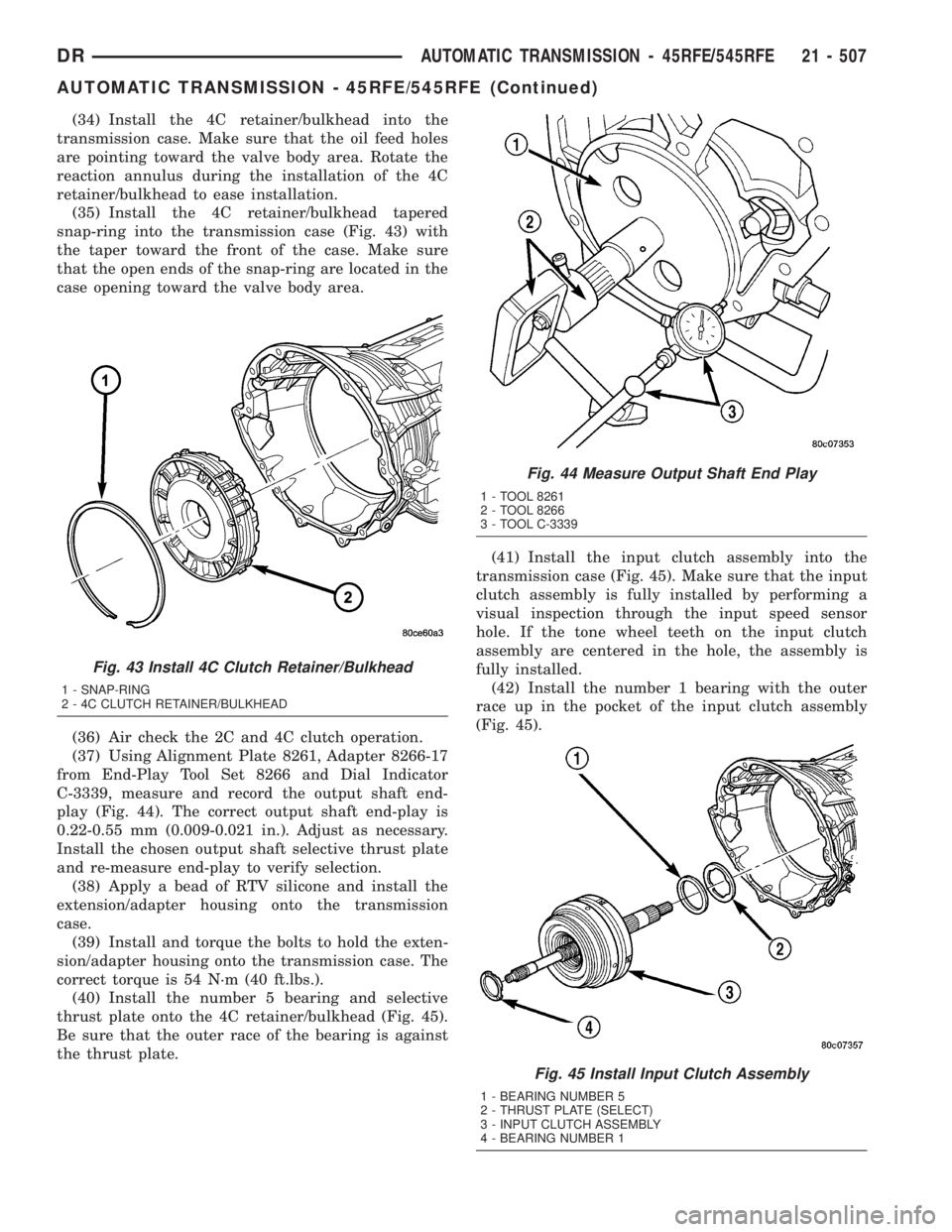
(34) Install the 4C retainer/bulkhead into the
transmission case. Make sure that the oil feed holes
are pointing toward the valve body area. Rotate the
reaction annulus during the installation of the 4C
retainer/bulkhead to ease installation.
(35) Install the 4C retainer/bulkhead tapered
snap-ring into the transmission case (Fig. 43) with
the taper toward the front of the case. Make sure
that the open ends of the snap-ring are located in the
case opening toward the valve body area.
(36) Air check the 2C and 4C clutch operation.
(37) Using Alignment Plate 8261, Adapter 8266-17
from End-Play Tool Set 8266 and Dial Indicator
C-3339, measure and record the output shaft end-
play (Fig. 44). The correct output shaft end-play is
0.22-0.55 mm (0.009-0.021 in.). Adjust as necessary.
Install the chosen output shaft selective thrust plate
and re-measure end-play to verify selection.
(38) Apply a bead of RTV silicone and install the
extension/adapter housing onto the transmission
case.
(39) Install and torque the bolts to hold the exten-
sion/adapter housing onto the transmission case. The
correct torque is 54 N´m (40 ft.lbs.).
(40) Install the number 5 bearing and selective
thrust plate onto the 4C retainer/bulkhead (Fig. 45).
Be sure that the outer race of the bearing is against
the thrust plate.(41) Install the input clutch assembly into the
transmission case (Fig. 45). Make sure that the input
clutch assembly is fully installed by performing a
visual inspection through the input speed sensor
hole. If the tone wheel teeth on the input clutch
assembly are centered in the hole, the assembly is
fully installed.
(42) Install the number 1 bearing with the outer
race up in the pocket of the input clutch assembly
(Fig. 45).
Fig. 43 Install 4C Clutch Retainer/Bulkhead
1 - SNAP-RING
2 - 4C CLUTCH RETAINER/BULKHEAD
Fig. 44 Measure Output Shaft End Play
1 - TOOL 8261
2 - TOOL 8266
3 - TOOL C-3339
Fig. 45 Install Input Clutch Assembly
1 - BEARING NUMBER 5
2 - THRUST PLATE (SELECT)
3 - INPUT CLUTCH ASSEMBLY
4 - BEARING NUMBER 1
DRAUTOMATIC TRANSMISSION - 45RFE/545RFE 21 - 507
AUTOMATIC TRANSMISSION - 45RFE/545RFE (Continued)