2003 DODGE RAM Output speed sensor
[x] Cancel search: Output speed sensorPage 2422 of 2895
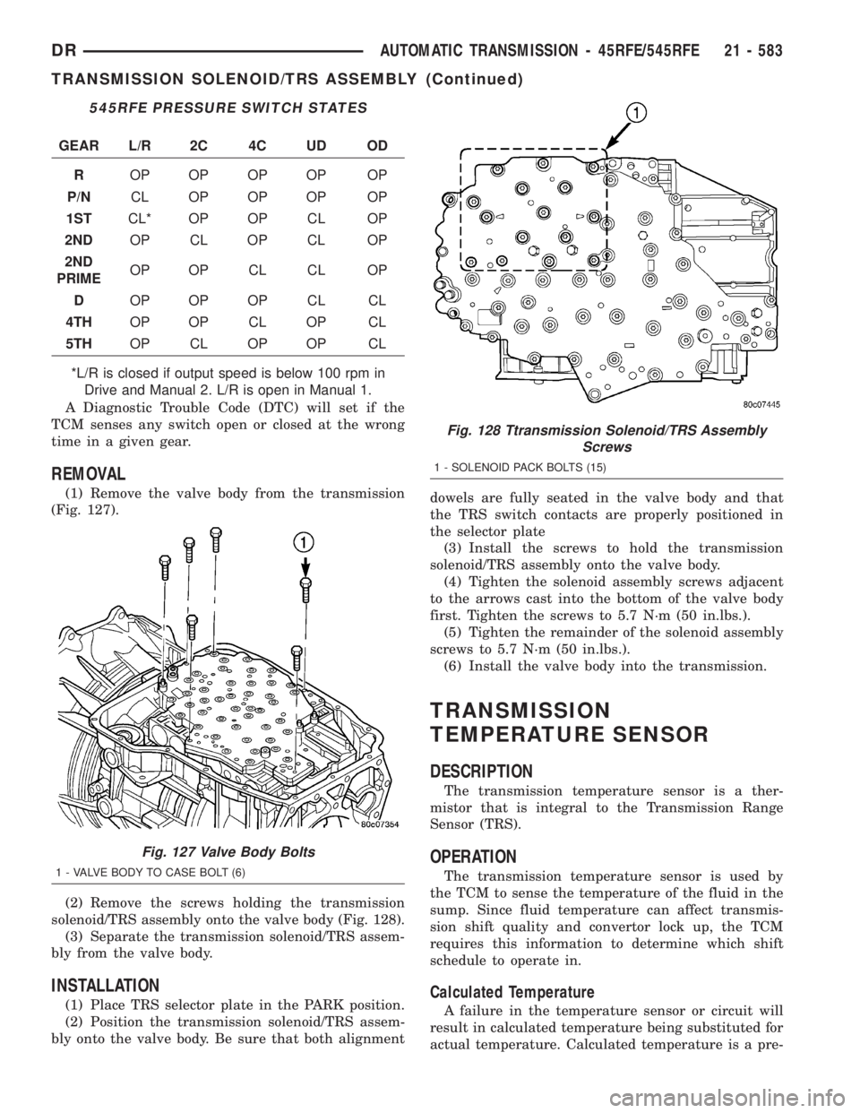
545RFE PRESSURE SWITCH STATES
GEAR L/R 2C 4C UD OD
ROP OP OP OP OP
P/NCL OP OP OP OP
1STCL* OP OP CL OP
2NDOP CL OP CL OP
2ND
PRIMEOP OP CL CL OP
DOP OP OP CL CL
4THOP OP CL OP CL
5THOP CL OP OP CL
*L/R is closed if output speed is below 100 rpm in
Drive and Manual 2. L/R is open in Manual 1.
A Diagnostic Trouble Code (DTC) will set if the
TCM senses any switch open or closed at the wrong
time in a given gear.
REMOVAL
(1) Remove the valve body from the transmission
(Fig. 127).
(2) Remove the screws holding the transmission
solenoid/TRS assembly onto the valve body (Fig. 128).
(3) Separate the transmission solenoid/TRS assem-
bly from the valve body.
INSTALLATION
(1) Place TRS selector plate in the PARK position.
(2) Position the transmission solenoid/TRS assem-
bly onto the valve body. Be sure that both alignmentdowels are fully seated in the valve body and that
the TRS switch contacts are properly positioned in
the selector plate
(3) Install the screws to hold the transmission
solenoid/TRS assembly onto the valve body.
(4) Tighten the solenoid assembly screws adjacent
to the arrows cast into the bottom of the valve body
first. Tighten the screws to 5.7 N´m (50 in.lbs.).
(5) Tighten the remainder of the solenoid assembly
screws to 5.7 N´m (50 in.lbs.).
(6) Install the valve body into the transmission.
TRANSMISSION
TEMPERATURE SENSOR
DESCRIPTION
The transmission temperature sensor is a ther-
mistor that is integral to the Transmission Range
Sensor (TRS).
OPERATION
The transmission temperature sensor is used by
the TCM to sense the temperature of the fluid in the
sump. Since fluid temperature can affect transmis-
sion shift quality and convertor lock up, the TCM
requires this information to determine which shift
schedule to operate in.
Calculated Temperature
A failure in the temperature sensor or circuit will
result in calculated temperature being substituted for
actual temperature. Calculated temperature is a pre-
Fig. 127 Valve Body Bolts
1 - VALVE BODY TO CASE BOLT (6)
Fig. 128 Ttransmission Solenoid/TRS Assembly
Screws
1 - SOLENOID PACK BOLTS (15)
DRAUTOMATIC TRANSMISSION - 45RFE/545RFE 21 - 583
TRANSMISSION SOLENOID/TRS ASSEMBLY (Continued)
Page 2430 of 2895
TRANSFER CASE - NV241 GENII
TABLE OF CONTENTS
page page
TRANSFER CASE - NV241 GENII
DESCRIPTION........................591
OPERATION..........................591
DIAGNOSIS AND TESTING - TRANSFER
CASE - NV241 GENII..................592
REMOVAL............................593
DISASSEMBLY........................593
CLEANING...........................602
INSPECTION.........................602
ASSEMBLY...........................604
INSTALLATION........................614
SPECIFICATIONS
TRANSFER CASE - NV241 GENII........614
SPECIAL TOOLS
TRANSFER CASE - NV241/NV243........615
EXTENSION HOUSING BUSHING AND SEAL
REMOVAL............................616INSTALLATION........................616
FLUID
STANDARD PROCEDURE - FLUID DRAIN AND
REFILL............................617
FRONT OUTPUT SHAFT SEAL
REMOVAL............................617
INSTALLATION........................618
POSITION SENSOR
DESCRIPTION........................618
OPERATION..........................619
REMOVAL............................619
INSTALLATION........................619
SHIFT LEVER
REMOVAL............................620
INSTALLATION........................621
ADJUSTMENTS
ADJUSTMENT - SHIFT LEVER..........622
TRANSFER CASE - NV241
GENII
DESCRIPTION
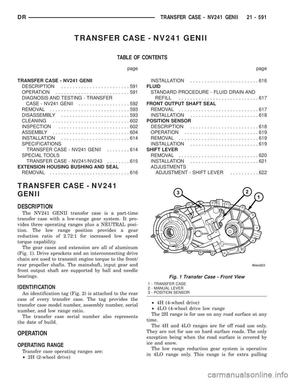
The NV241 GENII transfer case is a part-time
transfer case with a low-range gear system. It pro-
vides three operating ranges plus a NEUTRAL posi-
tion. The low range position provides a gear
reduction ratio of 2.72:1 for increased low speed
torque capability.
The gear cases and extension are all of aluminum
(Fig. 1). Drive sprockets and an interconnecting drive
chain are used to transmit engine torque to the front/
rear propeller shafts. The mainshaft, input gear and
front output shaft are supported by ball and needle
bearings.
IDENTIFICATION
An identification tag (Fig. 2) is attached to the rear
case of every transfer case. The tag provides the
transfer case model number, assembly number, serial
number, and low range ratio.
The transfer case serial number also represents
the date of build.
OPERATION
OPERATING RANGE
Transfer case operating ranges are:
²2H (2-wheel drive)²4H (4-wheel drive)
²4LO (4-wheel drive low range
The 2H range is for use on any road surface at any
time.
The 4H and 4LO ranges are for off road use only.
They are not for use on hard surface roads. The only
exception being when the road surface is covered by
ice and snow.
The low range reduction gear system is operative
in 4LO range only. This range is for extra pulling
Fig. 1 Transfer Case - Front View
1 - TRANSFER CASE
2 - MANUAL LEVER
3 - POSITION SENSOR
DRTRANSFER CASE - NV241 GENII 21 - 591
Page 2462 of 2895
TRANSFER CASE - NV271
TABLE OF CONTENTS
page page
TRANSFER CASE - NV271
DESCRIPTION........................623
OPERATION..........................623
DIAGNOSIS AND TESTING - TRANSFER
CASE - NV271.......................624
REMOVAL............................625
DISASSEMBLY........................625
CLEANING...........................635
INSPECTION.........................635
ASSEMBLY...........................637
INSTALLATION........................649
SPECIFICATIONS
TRANSFER CASE - NV271.............649
SPECIAL TOOLS
TRANSFER CASE NV271/NV273.........650
EXTENSION HOUSING SEAL AND DUST BOOT
REMOVAL............................652INSTALLATION........................652
FLUID
STANDARD PROCEDURE - FLUID DRAIN AND
REFILL............................652
FRONT OUTPUT SHAFT SEAL
REMOVAL............................653
INSTALLATION........................653
POSITION SENSOR
DESCRIPTION........................654
OPERATION..........................654
REMOVAL............................654
INSTALLATION........................654
SHIFT LEVER
REMOVAL............................655
INSTALLATION........................656
ADJUSTMENTS
ADJUSTMENT - SHIFT LEVER..........657
TRANSFER CASE - NV271
DESCRIPTION
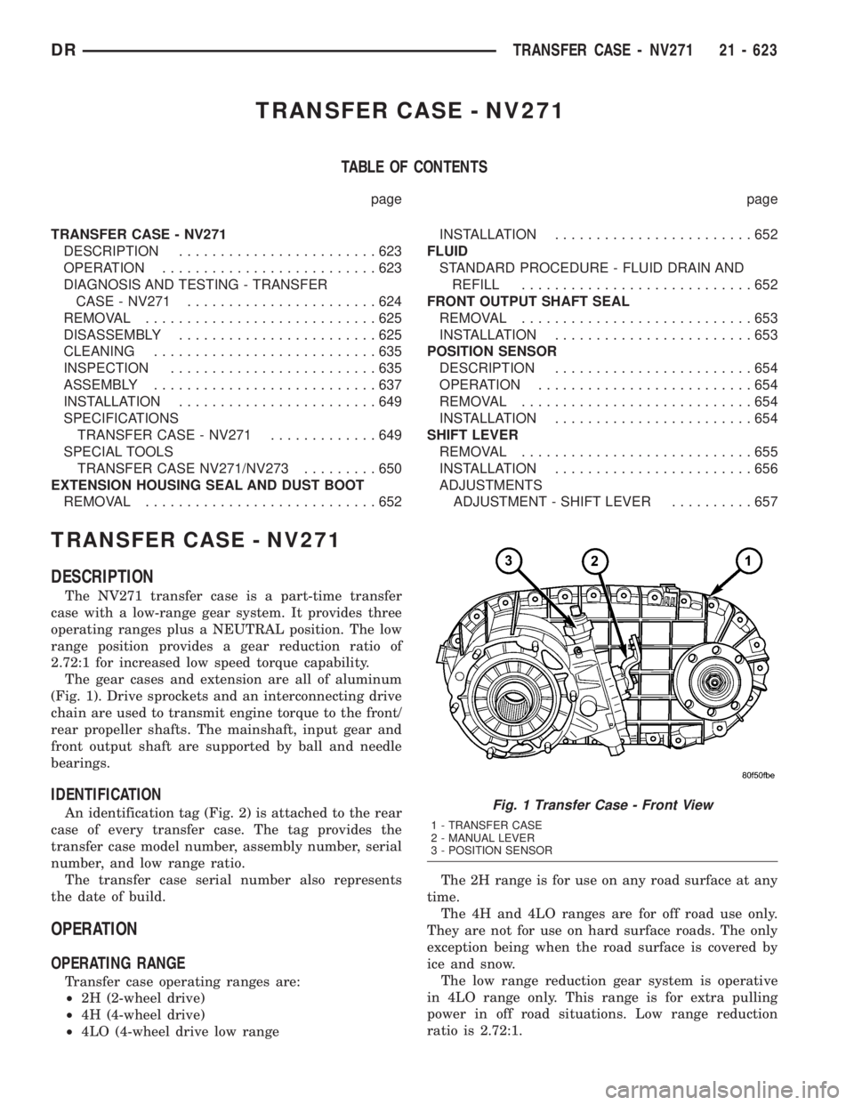
The NV271 transfer case is a part-time transfer
case with a low-range gear system. It provides three
operating ranges plus a NEUTRAL position. The low
range position provides a gear reduction ratio of
2.72:1 for increased low speed torque capability.
The gear cases and extension are all of aluminum
(Fig. 1). Drive sprockets and an interconnecting drive
chain are used to transmit engine torque to the front/
rear propeller shafts. The mainshaft, input gear and
front output shaft are supported by ball and needle
bearings.
IDENTIFICATION
An identification tag (Fig. 2) is attached to the rear
case of every transfer case. The tag provides the
transfer case model number, assembly number, serial
number, and low range ratio.
The transfer case serial number also represents
the date of build.
OPERATION
OPERATING RANGE
Transfer case operating ranges are:
²2H (2-wheel drive)
²4H (4-wheel drive)
²4LO (4-wheel drive low rangeThe 2H range is for use on any road surface at any
time.
The 4H and 4LO ranges are for off road use only.
They are not for use on hard surface roads. The only
exception being when the road surface is covered by
ice and snow.
The low range reduction gear system is operative
in 4LO range only. This range is for extra pulling
power in off road situations. Low range reduction
ratio is 2.72:1.
Fig. 1 Transfer Case - Front View
1 - TRANSFER CASE
2 - MANUAL LEVER
3 - POSITION SENSOR
DRTRANSFER CASE - NV271 21 - 623
Page 2497 of 2895
TRANSFER CASE - NV243
TABLE OF CONTENTS
page page
TRANSFER CASE - NV243
DESCRIPTION........................658
OPERATION..........................659
DIAGNOSIS AND TESTING - TRANSFER
CASE - NV243.......................659
REMOVAL............................660
DISASSEMBLY........................660
CLEANING...........................668
INSPECTION.........................668
ASSEMBLY...........................670
INSTALLATION........................679
SPECIFICATIONS
TRANSFER CASE - NV243.............680
SPECIAL TOOLS
TRANSFER CASE - NV241/NV243........680
EXTENSION HOUSING BUSHING AND SEAL
REMOVAL............................682
INSTALLATION........................682FLUID
STANDARD PROCEDURE - FLUID DRAIN AND
REFILL............................682
FRONT OUTPUT SHAFT SEAL
REMOVAL............................683
INSTALLATION........................683
MODE SENSOR
DESCRIPTION........................684
OPERATION..........................684
SELECTOR SWITCH
DESCRIPTION........................685
OPERATION..........................685
SHIFT MOTOR
DESCRIPTION........................686
OPERATION..........................686
REMOVAL............................686
INSTALLATION........................686
TRANSFER CASE - NV243
DESCRIPTION
The NV243 is an electronically controlled part-time
transfer case with a low range gear reduction system.
The NV243 has three operating ranges plus a NEU-
TRAL position. The low range system provides a gear
reduction ratio for increased low speed torque capa-
bility.
The geartrain is mounted in two aluminum case
halves attached with bolts. The mainshaft front and
rear bearings are mounted in aluminum retainer
housings bolted to the case halves.
OPERATING RANGES
Transfer case operating ranges are:
²2WD (2-wheel drive)
²4HI (4-wheel drive)
²4LO (4-wheel drive low range)
²NEUTRAL
The 2WD range is for use on any road surface at
any time.The 4HI and 4LO ranges are for off road use only.
They are not for use on hard surface roads. The only
exception being when the road surface is wet or slip-
pery or covered by ice and snow.
The low range reduction gear system is operative
in 4LO range only. This range is for extra pulling
power in off road situations. Low range reduction
ratio is 2.72:1.
SHIFT MECHANISM
Operating ranges are selected with a dash
mounted shift selector switch. The shift selector
switch provides a input to the Transfer Case Control
Module (TCCM) to indicate the driver's desire to
change operating ranges. The TCCM uses this input,
along with input from the transfer case mounted
mode sensor and information from the vehicle's bus,
to determine if a shift is permitted. If the TCCM
decides the shift is permitted, the TCCM controls the
shift motor, mounted to the exterior of the transfer
case, to perform the shift.
21 - 658 TRANSFER CASE - NV243DR
Page 2525 of 2895
²A flashing operating mode LED for the desired
gear indicates that a shift to that position has been
requested, but all of the driver controllable conditions
have not been met. This is in an attempt to notify
the driver that the transmission needs to be put into
NEUTRAL, the vehicle speed is too great, or some
other condition outlined (other than a diagnostic fail-
ure that would prevent this shift) elsewhere (Refer to
8 - ELECTRICAL/ELECTRONIC CONTROL MOD-
ULES/TRANSFER CASE CONTROL MODULE -
OPERATION) is not met. Note that this flashing will
continue indefinitely until the conditions are eventu-
ally met, or the selector switch position is changed,
or if diagnostic routines no longer allow the
requested shift.
²If the driver attempts to make a shift into trans-
fer case NEUTRAL, and any of the driver controlla-
ble conditions are not met, the request will be
ignored until all of the conditions are met or until
the NEUTRAL select button is released. Additionally
the neutral lamp will flash, or begin to flash while
the button is depressed and operator controllable
conditions are not being met. All of the LED's except
the Neutral will flash if any of the operator control-
lable conditions for shifting are not met while the
Neutral button is depressed. This9toggle9type of fea-
ture is necessary because the TCCM would interpret
another request immediately after the shift into
transfer case NEUTRAL has completed.
²No LED's illuminated indicate a fault in the
transfer case control system.
SHIFT MOTOR
DESCRIPTION
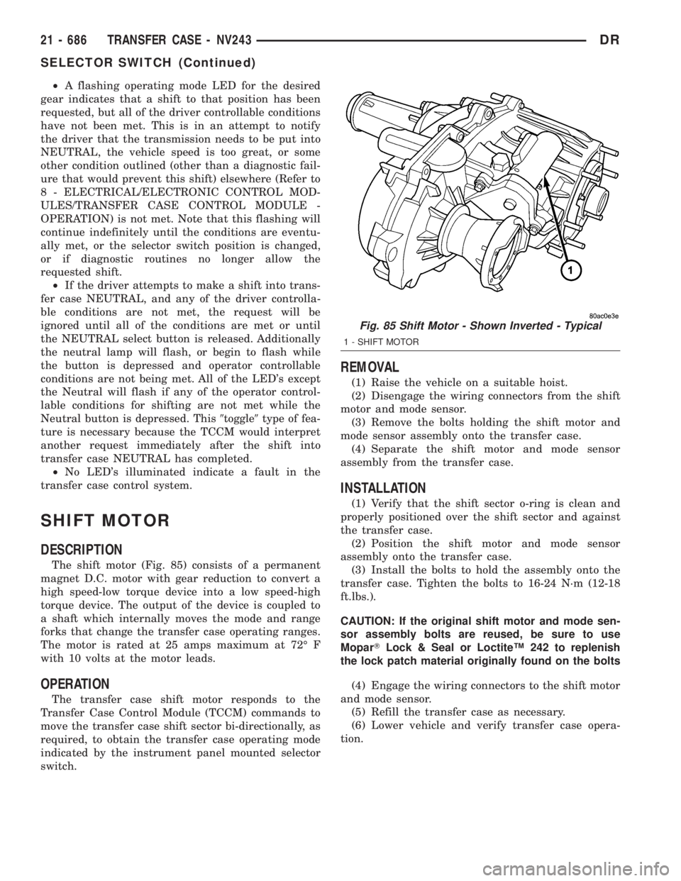
The shift motor (Fig. 85) consists of a permanent
magnet D.C. motor with gear reduction to convert a
high speed-low torque device into a low speed-high
torque device. The output of the device is coupled to
a shaft which internally moves the mode and range
forks that change the transfer case operating ranges.
The motor is rated at 25 amps maximum at 72É F
with 10 volts at the motor leads.
OPERATION
The transfer case shift motor responds to the
Transfer Case Control Module (TCCM) commands to
move the transfer case shift sector bi-directionally, as
required, to obtain the transfer case operating mode
indicated by the instrument panel mounted selector
switch.
REMOVAL
(1) Raise the vehicle on a suitable hoist.
(2) Disengage the wiring connectors from the shift
motor and mode sensor.
(3) Remove the bolts holding the shift motor and
mode sensor assembly onto the transfer case.
(4) Separate the shift motor and mode sensor
assembly from the transfer case.
INSTALLATION
(1) Verify that the shift sector o-ring is clean and
properly positioned over the shift sector and against
the transfer case.
(2) Position the shift motor and mode sensor
assembly onto the transfer case.
(3) Install the bolts to hold the assembly onto the
transfer case. Tighten the bolts to 16-24 N´m (12-18
ft.lbs.).
CAUTION: If the original shift motor and mode sen-
sor assembly bolts are reused, be sure to use
MoparTLock & Seal or LoctiteŸ 242 to replenish
the lock patch material originally found on the bolts
(4) Engage the wiring connectors to the shift motor
and mode sensor.
(5) Refill the transfer case as necessary.
(6) Lower vehicle and verify transfer case opera-
tion.
Fig. 85 Shift Motor - Shown Inverted - Typical
1 - SHIFT MOTOR
21 - 686 TRANSFER CASE - NV243DR
SELECTOR SWITCH (Continued)
Page 2526 of 2895
TRANSFER CASE - NV273
TABLE OF CONTENTS
page page
TRANSFER CASE - NV273
DESCRIPTION........................687
OPERATION..........................688
DIAGNOSIS AND TESTING - TRANSFER
CASE - NV273.......................688
REMOVAL............................689
DISASSEMBLY........................689
CLEANING...........................698
INSPECTION.........................699
ASSEMBLY...........................701
INSTALLATION........................713
SPECIFICATIONS
TRANSFER CASE - NV273.............713
SPECIAL TOOLS
TRANSFER CASE NV271/NV273.........714
EXTENSION HOUSING SEAL AND DUST BOOT
REMOVAL............................716
INSTALLATION........................716FLUID
STANDARD PROCEDURE - FLUID DRAIN AND
REFILL............................716
FRONT OUTPUT SHAFT SEAL
REMOVAL............................717
INSTALLATION........................717
MODE SENSOR
DESCRIPTION........................718
OPERATION..........................718
SELECTOR SWITCH
DESCRIPTION........................719
OPERATION..........................719
SHIFT MOTOR
DESCRIPTION........................720
OPERATION..........................720
REMOVAL............................720
INSTALLATION........................720
TRANSFER CASE - NV273
DESCRIPTION
The NV273 is an electronically controlled part-time
transfer case with a low range gear reduction system.
The NV273 has three operating ranges plus a NEU-
TRAL position. The low range system provides a gear
reduction ratio for increased low speed torque capa-
bility.
The geartrain is mounted in two aluminum case
halves attached with bolts. The mainshaft front and
rear bearings are mounted in aluminum case halves.
OPERATING RANGES
Transfer case operating ranges are:
²2WD (2-wheel drive)
²4HI (4-wheel drive)
²4LO (4-wheel drive low range)
²NEUTRAL
The 2WD range is for use on any road surface at
any time.The 4HI and 4LO ranges are for off road use only.
They are not for use on hard surface roads. The only
exception being when the road surface is wet or slip-
pery or covered by ice and snow.
The low range reduction gear system is operative
in 4LO range only. This range is for extra pulling
power in off road situations. Low range reduction
ratio is 2.72:1.
SHIFT MECHANISM
Operating ranges are selected with a dash
mounted shift selector switch. The shift selector
switch provides a input to the Transfer Case Control
Module (TCCM) to indicate the driver's desire to
change operating ranges. The TCCM uses this input,
along with input from the transfer case mounted
mode sensor and information from the vehicle's bus,
to determine if a shift is permitted. If the TCCM
decides the shift is permitted, the TCCM controls the
shift motor, mounted to the exterior of the transfer
case, to perform the shift.
DRTRANSFER CASE - NV273 21 - 687
Page 2559 of 2895
²A flashing operating mode LED for the desired
gear indicates that a shift to that position has been
requested, but all of the driver controllable conditions
have not been met. This is in an attempt to notify
the driver that the transmission needs to be put into
NEUTRAL, the vehicle speed is too great, or some
other condition outlined (other than a diagnostic fail-
ure that would prevent this shift) elsewhere (Refer to
8 - ELECTRICAL/ELECTRONIC CONTROL MOD-
ULES/TRANSFER CASE CONTROL MODULE -
OPERATION) is not met. Note that this flashing will
continue indefinitely until the conditions are eventu-
ally met, or the selector switch position is changed,
or if diagnostic routines no longer allow the
requested shift.
²If the driver attempts to make a shift into trans-
fer case NEUTRAL, and any of the driver controlla-
ble conditions are not met, the request will be
ignored until all of the conditions are met or until
the NEUTRAL select button is released. Additionally
the neutral lamp will flash, or begin to flash while
the button is depressed and operator controllable
conditions are not being met. All of the LED's except
the Neutral will flash if any of the operator control-
lable conditions for shifting are not met while the
Neutral button is depressed. This9toggle9type of fea-
ture is necessary because the TCCM would interpret
another request immediately after the shift into
transfer case NEUTRAL has completed.
²No LED's illuminated indicate a fault in the
transfer case control system.
SHIFT MOTOR
DESCRIPTION
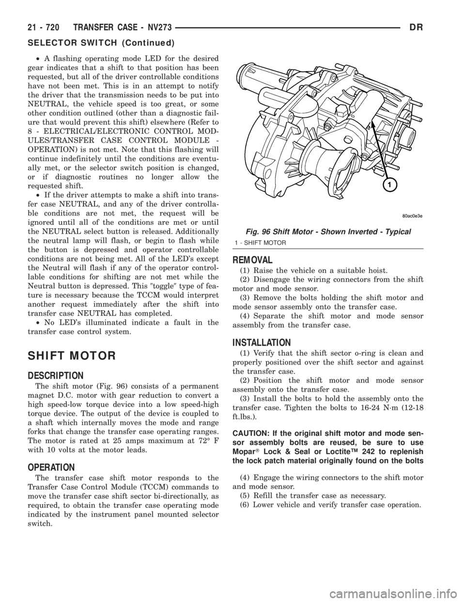
The shift motor (Fig. 96) consists of a permanent
magnet D.C. motor with gear reduction to convert a
high speed-low torque device into a low speed-high
torque device. The output of the device is coupled to
a shaft which internally moves the mode and range
forks that change the transfer case operating ranges.
The motor is rated at 25 amps maximum at 72É F
with 10 volts at the motor leads.
OPERATION
The transfer case shift motor responds to the
Transfer Case Control Module (TCCM) commands to
move the transfer case shift sector bi-directionally, as
required, to obtain the transfer case operating mode
indicated by the instrument panel mounted selector
switch.
REMOVAL
(1) Raise the vehicle on a suitable hoist.
(2) Disengage the wiring connectors from the shift
motor and mode sensor.
(3) Remove the bolts holding the shift motor and
mode sensor assembly onto the transfer case.
(4) Separate the shift motor and mode sensor
assembly from the transfer case.
INSTALLATION
(1) Verify that the shift sector o-ring is clean and
properly positioned over the shift sector and against
the transfer case.
(2) Position the shift motor and mode sensor
assembly onto the transfer case.
(3) Install the bolts to hold the assembly onto the
transfer case. Tighten the bolts to 16-24 N´m (12-18
ft.lbs.).
CAUTION: If the original shift motor and mode sen-
sor assembly bolts are reused, be sure to use
MoparTLock & Seal or LoctiteŸ 242 to replenish
the lock patch material originally found on the bolts
(4) Engage the wiring connectors to the shift motor
and mode sensor.
(5) Refill the transfer case as necessary.
(6) Lower vehicle and verify transfer case operation.
Fig. 96 Shift Motor - Shown Inverted - Typical
1 - SHIFT MOTOR
21 - 720 TRANSFER CASE - NV273DR
SELECTOR SWITCH (Continued)
Page 2790 of 2895
INSTALLATION
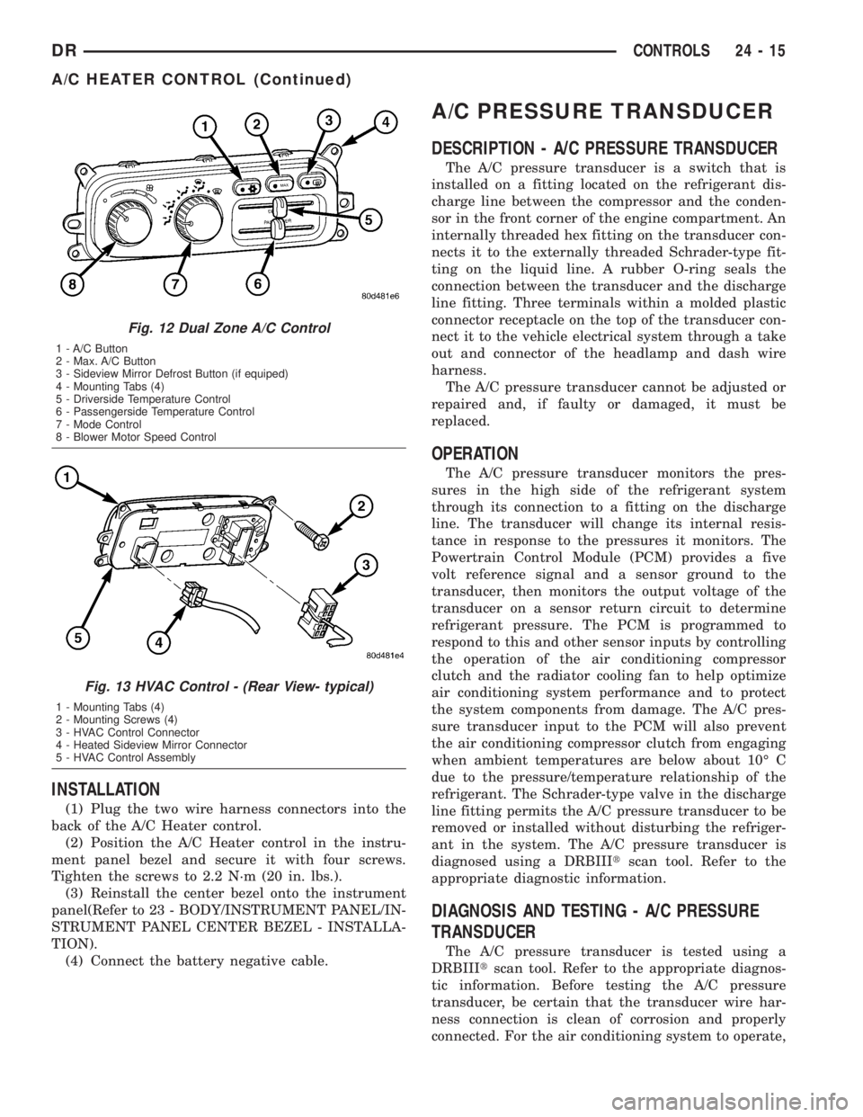
(1) Plug the two wire harness connectors into the
back of the A/C Heater control.
(2) Position the A/C Heater control in the instru-
ment panel bezel and secure it with four screws.
Tighten the screws to 2.2 N´m (20 in. lbs.).
(3) Reinstall the center bezel onto the instrument
panel(Refer to 23 - BODY/INSTRUMENT PANEL/IN-
STRUMENT PANEL CENTER BEZEL - INSTALLA-
TION).
(4) Connect the battery negative cable.
A/C PRESSURE TRANSDUCER
DESCRIPTION - A/C PRESSURE TRANSDUCER
The A/C pressure transducer is a switch that is
installed on a fitting located on the refrigerant dis-
charge line between the compressor and the conden-
sor in the front corner of the engine compartment. An
internally threaded hex fitting on the transducer con-
nects it to the externally threaded Schrader-type fit-
ting on the liquid line. A rubber O-ring seals the
connection between the transducer and the discharge
line fitting. Three terminals within a molded plastic
connector receptacle on the top of the transducer con-
nect it to the vehicle electrical system through a take
out and connector of the headlamp and dash wire
harness.
The A/C pressure transducer cannot be adjusted or
repaired and, if faulty or damaged, it must be
replaced.
OPERATION
The A/C pressure transducer monitors the pres-
sures in the high side of the refrigerant system
through its connection to a fitting on the discharge
line. The transducer will change its internal resis-
tance in response to the pressures it monitors. The
Powertrain Control Module (PCM) provides a five
volt reference signal and a sensor ground to the
transducer, then monitors the output voltage of the
transducer on a sensor return circuit to determine
refrigerant pressure. The PCM is programmed to
respond to this and other sensor inputs by controlling
the operation of the air conditioning compressor
clutch and the radiator cooling fan to help optimize
air conditioning system performance and to protect
the system components from damage. The A/C pres-
sure transducer input to the PCM will also prevent
the air conditioning compressor clutch from engaging
when ambient temperatures are below about 10É C
due to the pressure/temperature relationship of the
refrigerant. The Schrader-type valve in the discharge
line fitting permits the A/C pressure transducer to be
removed or installed without disturbing the refriger-
ant in the system. The A/C pressure transducer is
diagnosed using a DRBIIItscan tool. Refer to the
appropriate diagnostic information.
DIAGNOSIS AND TESTING - A/C PRESSURE
TRANSDUCER
The A/C pressure transducer is tested using a
DRBIIItscan tool. Refer to the appropriate diagnos-
tic information. Before testing the A/C pressure
transducer, be certain that the transducer wire har-
ness connection is clean of corrosion and properly
connected. For the air conditioning system to operate,
Fig. 12 Dual Zone A/C Control
1 - A/C Button
2 - Max. A/C Button
3 - Sideview Mirror Defrost Button (if equiped)
4 - Mounting Tabs (4)
5 - Driverside Temperature Control
6 - Passengerside Temperature Control
7 - Mode Control
8 - Blower Motor Speed Control
Fig. 13 HVAC Control - (Rear View- typical)
1 - Mounting Tabs (4)
2 - Mounting Screws (4)
3 - HVAC Control Connector
4 - Heated Sideview Mirror Connector
5 - HVAC Control Assembly
DRCONTROLS 24 - 15
A/C HEATER CONTROL (Continued)