2003 DODGE RAM clutch
[x] Cancel search: clutchPage 2784 of 2895
CONTROLS
TABLE OF CONTENTS
page page
A/C COMPRESSOR CLUTCH
DESCRIPTION..........................9
OPERATION............................9
DIAGNOSIS AND TESTING - A/C
COMPRESSOR CLUTCH COIL...........10
STANDARD PROCEDURE - A/C
COMPRESSOR CLUTCH BREAK-IN.......10
REMOVAL.............................10
INSPECTION..........................12
INSTALLATION.........................12
A/C COMPRESSOR CLUTCH RELAY
DESCRIPTION.........................13
OPERATION...........................13
DIAGNOSIS AND TESTING - COMPRESSOR
CLUTCH RELAY......................13
REMOVAL.............................14
INSTALLATION.........................14
A/C HEATER CONTROL
DESCRIPTION.........................14
REMOVAL.............................14
INSTALLATION.........................15
A/C PRESSURE TRANSDUCER
DESCRIPTION - A/C PRESSURE
TRANSDUCER.......................15
OPERATION...........................15
DIAGNOSIS AND TESTING - A/C PRESSURE
TRANSDUCER.......................15
REMOVAL.............................16
INSTALLATION.........................16
BLEND DOOR ACTUATOR
DESCRIPTION.........................16
OPERATION...........................16REMOVAL.............................17
INSTALLATION.........................17
BLOWER MOTOR RESISTOR BLOCK
DESCRIPTION.........................17
OPERATION...........................17
DIAGNOSIS AND TESTING - BLOWER
MOTOR RESISTOR....................18
REMOVAL.............................18
INSTALLATION.........................18
BLOWER MOTOR SWITCH
DESCRIPTION.........................18
OPERATION...........................18
DIAGNOSIS AND TESTING - BLOWER
MOTOR SWITCH......................18
REMOVAL.............................19
INSTALLATION.........................19
DEFROST DOOR ACTUATOR
REMOVAL - FLOOR - DEFROST DOOR
ACTUATOR..........................19
INSTALLATION - FLOOR - DEFROST DOOR
ACTUATOR..........................20
MODE DOOR ACTUATOR
DESCRIPTION.........................20
OPERATION...........................21
REMOVAL.............................21
INSTALLATION.........................22
RECIRCULATION DOOR ACTUATOR
DESCRIPTION.........................22
OPERATION...........................22
REMOVAL.............................22
INSTALLATION.........................23
A/C COMPRESSOR CLUTCH
DESCRIPTION
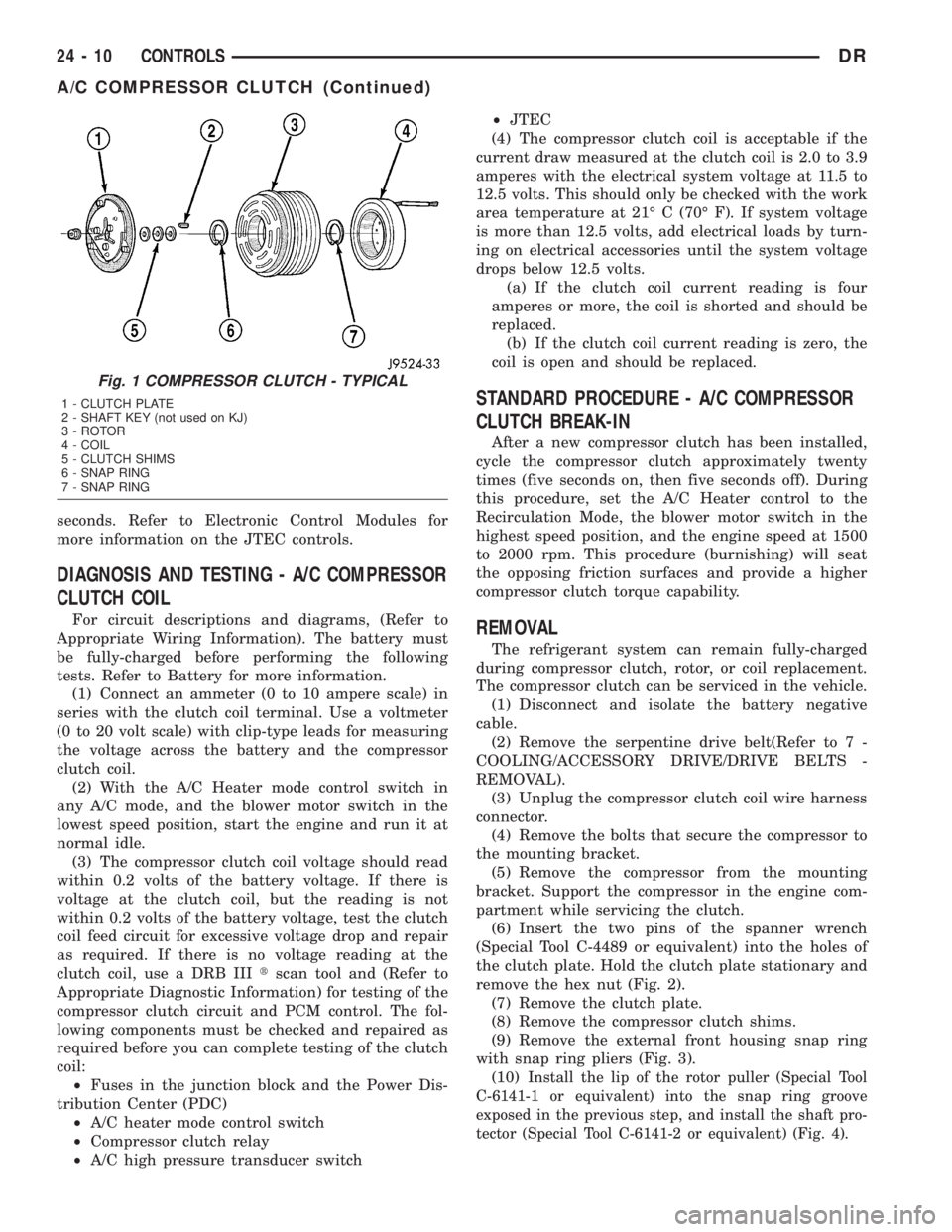
The compressor clutch assembly consists of a sta-
tionary electromagnetic coil, a rotor bearing and
rotor assembly, and a clutch plate (Fig. 1). The elec-
tromagnetic coil unit and the rotor bearing and rotor
assembly are each retained on the nose of the com-
pressor front housing with snap rings. The clutch
plate is keyed to the compressor shaft and secured
with a nut. These components provide the means to
engage and disengage the compressor from the
engine serpentine accessory drive belt.
OPERATION
When the clutch coil is energized, it magnetically
draws the clutch into contact with the rotor and
drives the compressor shaft. When the coil is not
energized, the rotor freewheels on the clutch rotor
bearing, which is part of the rotor. The compressor
clutch and coil are the only serviced parts on the
compressor.
The compressor clutch engagement is controlled by
several components: the A/C Heater mode control
switch, the A/C high pressure transducer, the com-
pressor clutch relay, and the (JTEC). The JTEC may
delay compressor clutch engagement for up to thirty
DRCONTROLS 24 - 9
Page 2785 of 2895
seconds. Refer to Electronic Control Modules for
more information on the JTEC controls.
DIAGNOSIS AND TESTING - A/C COMPRESSOR
CLUTCH COIL
For circuit descriptions and diagrams, (Refer to
Appropriate Wiring Information). The battery must
be fully-charged before performing the following
tests. Refer to Battery for more information.
(1) Connect an ammeter (0 to 10 ampere scale) in
series with the clutch coil terminal. Use a voltmeter
(0 to 20 volt scale) with clip-type leads for measuring
the voltage across the battery and the compressor
clutch coil.
(2) With the A/C Heater mode control switch in
any A/C mode, and the blower motor switch in the
lowest speed position, start the engine and run it at
normal idle.
(3) The compressor clutch coil voltage should read
within 0.2 volts of the battery voltage. If there is
voltage at the clutch coil, but the reading is not
within 0.2 volts of the battery voltage, test the clutch
coil feed circuit for excessive voltage drop and repair
as required. If there is no voltage reading at the
clutch coil, use a DRB IIItscan tool and (Refer to
Appropriate Diagnostic Information) for testing of the
compressor clutch circuit and PCM control. The fol-
lowing components must be checked and repaired as
required before you can complete testing of the clutch
coil:
²Fuses in the junction block and the Power Dis-
tribution Center (PDC)
²A/C heater mode control switch
²Compressor clutch relay
²A/C high pressure transducer switch²JTEC
(4) The compressor clutch coil is acceptable if the
current draw measured at the clutch coil is 2.0 to 3.9
amperes with the electrical system voltage at 11.5 to
12.5 volts. This should only be checked with the work
area temperature at 21É C (70É F). If system voltage
is more than 12.5 volts, add electrical loads by turn-
ing on electrical accessories until the system voltage
drops below 12.5 volts.
(a) If the clutch coil current reading is four
amperes or more, the coil is shorted and should be
replaced.
(b) If the clutch coil current reading is zero, the
coil is open and should be replaced.
STANDARD PROCEDURE - A/C COMPRESSOR
CLUTCH BREAK-IN
After a new compressor clutch has been installed,
cycle the compressor clutch approximately twenty
times (five seconds on, then five seconds off). During
this procedure, set the A/C Heater control to the
Recirculation Mode, the blower motor switch in the
highest speed position, and the engine speed at 1500
to 2000 rpm. This procedure (burnishing) will seat
the opposing friction surfaces and provide a higher
compressor clutch torque capability.
REMOVAL
The refrigerant system can remain fully-charged
during compressor clutch, rotor, or coil replacement.
The compressor clutch can be serviced in the vehicle.
(1) Disconnect and isolate the battery negative
cable.
(2) Remove the serpentine drive belt(Refer to 7 -
COOLING/ACCESSORY DRIVE/DRIVE BELTS -
REMOVAL).
(3) Unplug the compressor clutch coil wire harness
connector.
(4) Remove the bolts that secure the compressor to
the mounting bracket.
(5) Remove the compressor from the mounting
bracket. Support the compressor in the engine com-
partment while servicing the clutch.
(6) Insert the two pins of the spanner wrench
(Special Tool C-4489 or equivalent) into the holes of
the clutch plate. Hold the clutch plate stationary and
remove the hex nut (Fig. 2).
(7) Remove the clutch plate.
(8) Remove the compressor clutch shims.
(9) Remove the external front housing snap ring
with snap ring pliers (Fig. 3).
(10)
Install the lip of the rotor puller (Special Tool
C-6141-1 or equivalent) into the snap ring groove
exposed in the previous step, and install the shaft pro-
tector (Special Tool C-6141-2 or equivalent) (Fig. 4).
Fig. 1 COMPRESSOR CLUTCH - TYPICAL
1 - CLUTCH PLATE
2 - SHAFT KEY (not used on KJ)
3 - ROTOR
4 - COIL
5 - CLUTCH SHIMS
6 - SNAP RING
7 - SNAP RING
24 - 10 CONTROLSDR
A/C COMPRESSOR CLUTCH (Continued)
Page 2786 of 2895
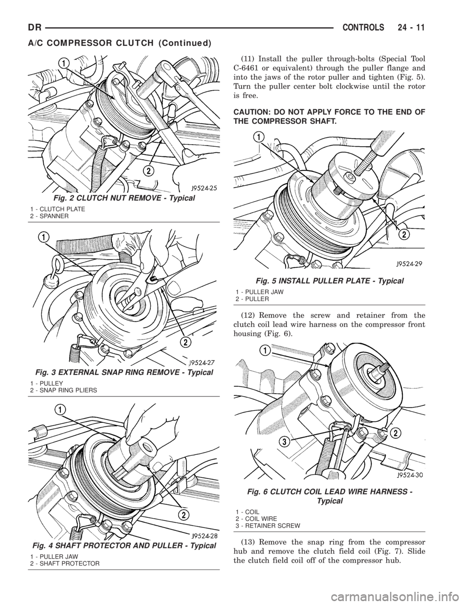
(11) Install the puller through-bolts (Special Tool
C-6461 or equivalent) through the puller flange and
into the jaws of the rotor puller and tighten (Fig. 5).
Turn the puller center bolt clockwise until the rotor
is free.
CAUTION: DO NOT APPLY FORCE TO THE END OF
THE COMPRESSOR SHAFT.
(12) Remove the screw and retainer from the
clutch coil lead wire harness on the compressor front
housing (Fig. 6).
(13) Remove the snap ring from the compressor
hub and remove the clutch field coil (Fig. 7). Slide
the clutch field coil off of the compressor hub.
Fig. 2 CLUTCH NUT REMOVE - Typical
1 - CLUTCH PLATE
2 - SPANNER
Fig. 3 EXTERNAL SNAP RING REMOVE - Typical
1 - PULLEY
2 - SNAP RING PLIERS
Fig. 4 SHAFT PROTECTOR AND PULLER - Typical
1 - PULLER JAW
2 - SHAFT PROTECTOR
Fig. 5 INSTALL PULLER PLATE - Typical
1 - PULLER JAW
2 - PULLER
Fig. 6 CLUTCH COIL LEAD WIRE HARNESS -
Typical
1 - COIL
2 - COIL WIRE
3 - RETAINER SCREW
DRCONTROLS 24 - 11
A/C COMPRESSOR CLUTCH (Continued)
Page 2787 of 2895
INSPECTION
Examine the friction surfaces of the clutch rotor
and the clutch plate for wear. The rotor and clutch
plate should be replaced if there is excessive wear or
scoring.
If the friction surfaces are oily, inspect the shaft
and nose area of the compressor for oil. Remove the
felt from the front cover. If the felt is saturated with
oil, the shaft seal is leaking and the compressor must
be replaced.
Check the rotor bearing for roughness or excessive
leakage of grease. Replace the rotor and clutch plate,
if required.
INSTALLATION
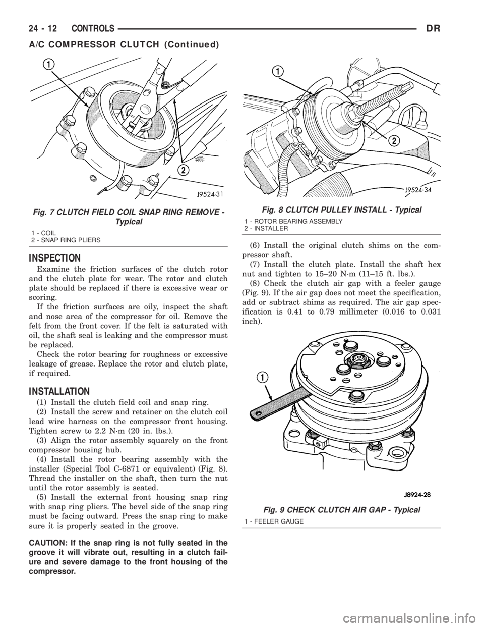
(1) Install the clutch field coil and snap ring.
(2) Install the screw and retainer on the clutch coil
lead wire harness on the compressor front housing.
Tighten screw to 2.2 N´m (20 in. lbs.).
(3) Align the rotor assembly squarely on the front
compressor housing hub.
(4) Install the rotor bearing assembly with the
installer (Special Tool C-6871 or equivalent) (Fig. 8).
Thread the installer on the shaft, then turn the nut
until the rotor assembly is seated.
(5) Install the external front housing snap ring
with snap ring pliers. The bevel side of the snap ring
must be facing outward. Press the snap ring to make
sure it is properly seated in the groove.
CAUTION: If the snap ring is not fully seated in the
groove it will vibrate out, resulting in a clutch fail-
ure and severe damage to the front housing of the
compressor.(6) Install the original clutch shims on the com-
pressor shaft.
(7) Install the clutch plate. Install the shaft hex
nut and tighten to 15±20 N´m (11±15 ft. lbs.).
(8) Check the clutch air gap with a feeler gauge
(Fig. 9). If the air gap does not meet the specification,
add or subtract shims as required. The air gap spec-
ification is 0.41 to 0.79 millimeter (0.016 to 0.031
inch).
Fig. 7 CLUTCH FIELD COIL SNAP RING REMOVE -
Typical
1 - COIL
2 - SNAP RING PLIERS
Fig. 8 CLUTCH PULLEY INSTALL - Typical
1 - ROTOR BEARING ASSEMBLY
2 - INSTALLER
Fig. 9 CHECK CLUTCH AIR GAP - Typical
1 - FEELER GAUGE
24 - 12 CONTROLSDR
A/C COMPRESSOR CLUTCH (Continued)
Page 2788 of 2895
NOTE: The air gap is determined by the spacer
shims. When installing an original, or a new clutch
assembly, try the original shims first. When install-
ing a new clutch onto a compressor that previously
did not have a clutch, use a 1.0, 0.50, and 0.13 mil-
limeter (0.040, 0.020, and 0.005 inch) shims from the
new clutch hardware package that is provided with
the new clutch.
(9) To complete the procedure, (Refer to 24 -
HEATING & AIR CONDITIONING/PLUMBING/A/C
COMPRESSOR - INSTALLATION).
A/C COMPRESSOR CLUTCH
RELAY
DESCRIPTION
The compressor clutch relay is a International
Standards Organization (ISO) micro-relay. The termi-
nal designations and functions are the same as a con-
ventional ISO relay. However, the micro-relay
terminal orientation (footprint) is different, the cur-
rent capacity is lower, and the relay case dimensions
are smaller than those of the conventional ISO relay.
The compressor clutch relay is located in the Power
Distribution Center (PDC) in the engine compart-
ment. Refer to the PDC label for relay identification
and location.
OPERATION
The compressor clutch relay is a electromechanical
device that switches battery current to the compres-
sor clutch coil when the Powertrain Control Module
(PCM) grounds the coil side of the relay. The PCM
responds to inputs from the A/C Heater mode control
switch, the A/C low pressure switch, and the A/C
high pressure switch. (Refer to 24 - HEATING & AIR
CONDITIONING/CONTROLS/A/C COMPRESSOR
CLUTCH RELAY - DIAGNOSIS AND TESTING)
The compressor clutch relay cannot be repaired
and, if faulty or damaged, it must be replaced.
DIAGNOSIS AND TESTING - COMPRESSOR
CLUTCH RELAY
RELAY TEST
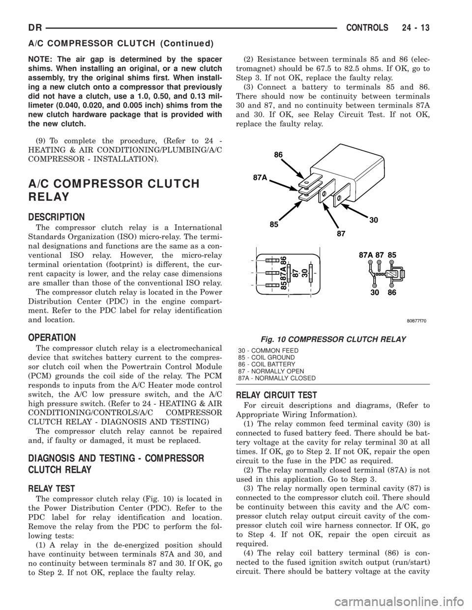
The compressor clutch relay (Fig. 10) is located in
the Power Distribution Center (PDC). Refer to the
PDC label for relay identification and location.
Remove the relay from the PDC to perform the fol-
lowing tests:
(1) A relay in the de-energized position should
have continuity between terminals 87A and 30, and
no continuity between terminals 87 and 30. If OK, go
to Step 2. If not OK, replace the faulty relay.(2) Resistance between terminals 85 and 86 (elec-
tromagnet) should be 67.5 to 82.5 ohms. If OK, go to
Step 3. If not OK, replace the faulty relay.
(3) Connect a battery to terminals 85 and 86.
There should now be continuity between terminals
30 and 87, and no continuity between terminals 87A
and 30. If OK, see Relay Circuit Test. If not OK,
replace the faulty relay.
RELAY CIRCUIT TEST
For circuit descriptions and diagrams, (Refer to
Appropriate Wiring Information).
(1) The relay common feed terminal cavity (30) is
connected to fused battery feed. There should be bat-
tery voltage at the cavity for relay terminal 30 at all
times. If OK, go to Step 2. If not OK, repair the open
circuit to the fuse in the PDC as required.
(2) The relay normally closed terminal (87A) is not
used in this application. Go to Step 3.
(3) The relay normally open terminal cavity (87) is
connected to the compressor clutch coil. There should
be continuity between this cavity and the A/C com-
pressor clutch relay output circuit cavity of the com-
pressor clutch coil wire harness connector. If OK, go
to Step 4. If not OK, repair the open circuit as
required.
(4) The relay coil battery terminal (86) is con-
nected to the fused ignition switch output (run/start)
circuit. There should be battery voltage at the cavity
Fig. 10 COMPRESSOR CLUTCH RELAY
30 - COMMON FEED
85 - COIL GROUND
86 - COIL BATTERY
87 - NORMALLY OPEN
87A - NORMALLY CLOSED
DRCONTROLS 24 - 13
A/C COMPRESSOR CLUTCH (Continued)
Page 2789 of 2895
for relay terminal 86 with the ignition switch in the
On position. If OK, go to Step 5. If not OK, repair the
open circuit to the fuse in the junction block as
required.
(5) The coil ground terminal cavity (85) is switched
to ground through the Powertrain Control Module
(PCM). There should be continuity between this cav-
ity and the A/C compressor clutch relay control cir-
cuit cavity of the PCM wire harness connector C
(gray) at all times. If not OK, repair the open circuit
as required.
REMOVAL
(1) Disconnect and isolate the battery negative
cable.
(2) Remove the cover from the Power Distribution
Center (PDC).
(3) Refer to the label on the PDC for compressor
clutch relay identification and location.
(4) Unplug the compressor clutch relay from the
PDC.
INSTALLATION
(1) Install the compressor clutch relay by aligning
the relay terminals with the cavities in the PDC and
pushing the relay firmly into place.
(2) Install the PDC cover.
(3) Connect the battery negative cable.
(4) Test the relay operation.
A/C HEATER CONTROL
DESCRIPTION
The A/C heater system uses a seriers of electrical
controls. These controls provide the vehicle operator
with a number of setting options to help control the
climate and comfort within the vehicle. Refer to the
owner's manual in the vehicle glove box for more
information on the features, use, and suggested oper-
ation of these controls.
The A/C heater control - (Single Zone) or (Dual
Zone) panel is located to the right of the instrument
cluster on the instrument panel.
The control panel contains a rotary-type tempera-
ture control, a rotary-type mode control switch knob,
and a rotary-type blower motor speed switch knob.
The control also has a push button to activate the
Optional side view mirrors defroster elements and to
turn the A/C on.
The Dual Zone HVAC control panel contains a pair
of slider-type temperature controls, a rotary-type
mode control switch knob and a rotary-type blower
motor speed switch knob. The control also has but-
tons to turn the A/C ON, Set it on Max A/C and for
the Optional Heated Sideview Mirrors.The A/C heater control panel cannot be repaired. If
faulty or damaged, the entire unit must be replaced.
The illumination lamps are available for service
replacement.
REMOVAL
WARNING: ON VEHICLES EQUIPPED WITH AIR-
BAGS, DISABLE THE AIRBAG SYSTEM BEFORE
ATTEMPTING ANY STEERING WHEEL, STEERING
COLUMN, OR INSTRUMENT PANEL COMPONENT
DIAGNOSIS OR SERVICE. DISCONNECT AND ISO-
LATE THE BATTERY NEGATIVE (GROUND) CABLE,
THEN WAIT TWO MINUTES FOR THE AIRBAG SYS-
TEM CAPACITOR TO DISCHARGE BEFORE PER-
FORMING FURTHER DIAGNOSIS OR SERVICE. THIS
IS THE ONLY SURE WAY TO DISABLE THE AIRBAG
SYSTEM. FAILURE TO TAKE THE PROPER PRE-
CAUTIONS COULD RESULT IN AN ACCIDENTAL
AIRBAG DEPLOYMENT AND POSSIBLE PERSONAL
INJURY.
(1) Disconnect and isolate the battery negative
cable.
(2) Remove the center bezel from the instrument
panel(Refer to 23 - BODY/INSTRUMENT PANEL/IN-
STRUMENT PANEL CENTER BEZEL - REMOVAL).
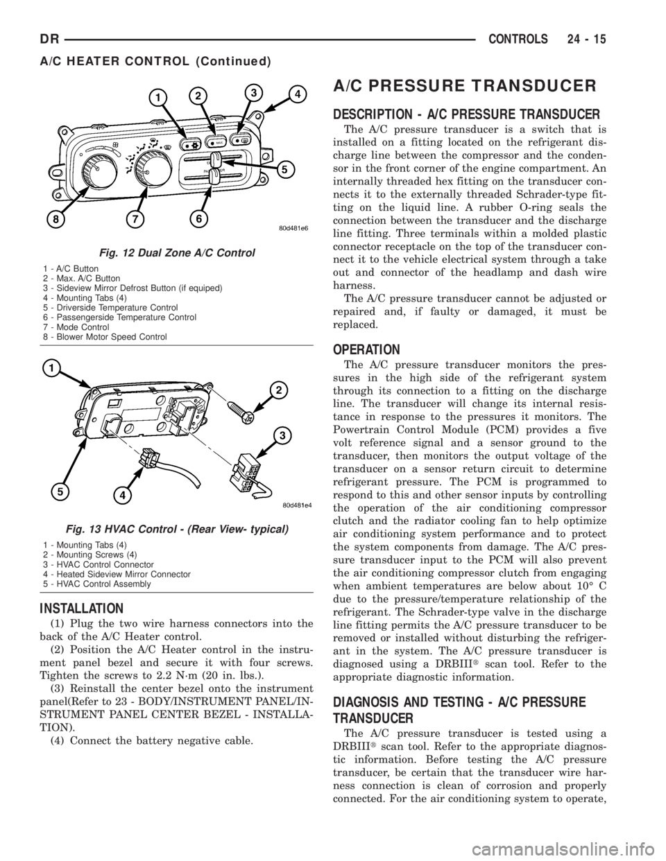
(3) Remove the screws that secure the A/C Heater
control to the instrument panel (Fig. 11) or (Fig. 12).
(4) Pull the A/C Heater control assembly away
from the instrument panel far enough to access the
connections on the back of the control.
(5) Unplug the wire harness connectors from the
back of the A/C Heater control (Fig. 13).
Fig. 11 Single Zone HVAC Control
1 - Mounting Tab (4)
2 - A/C Button
3 - Sideview Mirror Defroster Button (if equiped)
4 - Mode Control
5 - Blend Air Control
6 - Blower Motor Speed Control
24 - 14 CONTROLSDR
A/C COMPRESSOR CLUTCH RELAY (Continued)
Page 2790 of 2895
INSTALLATION
(1) Plug the two wire harness connectors into the
back of the A/C Heater control.
(2) Position the A/C Heater control in the instru-
ment panel bezel and secure it with four screws.
Tighten the screws to 2.2 N´m (20 in. lbs.).
(3) Reinstall the center bezel onto the instrument
panel(Refer to 23 - BODY/INSTRUMENT PANEL/IN-
STRUMENT PANEL CENTER BEZEL - INSTALLA-
TION).
(4) Connect the battery negative cable.
A/C PRESSURE TRANSDUCER
DESCRIPTION - A/C PRESSURE TRANSDUCER
The A/C pressure transducer is a switch that is
installed on a fitting located on the refrigerant dis-
charge line between the compressor and the conden-
sor in the front corner of the engine compartment. An
internally threaded hex fitting on the transducer con-
nects it to the externally threaded Schrader-type fit-
ting on the liquid line. A rubber O-ring seals the
connection between the transducer and the discharge
line fitting. Three terminals within a molded plastic
connector receptacle on the top of the transducer con-
nect it to the vehicle electrical system through a take
out and connector of the headlamp and dash wire
harness.
The A/C pressure transducer cannot be adjusted or
repaired and, if faulty or damaged, it must be
replaced.
OPERATION
The A/C pressure transducer monitors the pres-
sures in the high side of the refrigerant system
through its connection to a fitting on the discharge
line. The transducer will change its internal resis-
tance in response to the pressures it monitors. The
Powertrain Control Module (PCM) provides a five
volt reference signal and a sensor ground to the
transducer, then monitors the output voltage of the
transducer on a sensor return circuit to determine
refrigerant pressure. The PCM is programmed to
respond to this and other sensor inputs by controlling
the operation of the air conditioning compressor
clutch and the radiator cooling fan to help optimize
air conditioning system performance and to protect
the system components from damage. The A/C pres-
sure transducer input to the PCM will also prevent
the air conditioning compressor clutch from engaging
when ambient temperatures are below about 10É C
due to the pressure/temperature relationship of the
refrigerant. The Schrader-type valve in the discharge
line fitting permits the A/C pressure transducer to be
removed or installed without disturbing the refriger-
ant in the system. The A/C pressure transducer is
diagnosed using a DRBIIItscan tool. Refer to the
appropriate diagnostic information.
DIAGNOSIS AND TESTING - A/C PRESSURE
TRANSDUCER
The A/C pressure transducer is tested using a
DRBIIItscan tool. Refer to the appropriate diagnos-
tic information. Before testing the A/C pressure
transducer, be certain that the transducer wire har-
ness connection is clean of corrosion and properly
connected. For the air conditioning system to operate,
Fig. 12 Dual Zone A/C Control
1 - A/C Button
2 - Max. A/C Button
3 - Sideview Mirror Defrost Button (if equiped)
4 - Mounting Tabs (4)
5 - Driverside Temperature Control
6 - Passengerside Temperature Control
7 - Mode Control
8 - Blower Motor Speed Control
Fig. 13 HVAC Control - (Rear View- typical)
1 - Mounting Tabs (4)
2 - Mounting Screws (4)
3 - HVAC Control Connector
4 - Heated Sideview Mirror Connector
5 - HVAC Control Assembly
DRCONTROLS 24 - 15
A/C HEATER CONTROL (Continued)
Page 2811 of 2895
nents, caused by condenser air flow restriction or an
overcharge of refrigerant.
OPERATION
OPERATION
The compressor is driven by the engine through an
electric clutch, drive rotor and belt arrangement. The
compressor is lubricated by refrigerant oil that is cir-
culated throughout the refrigerant system with the
refrigerant.
The compressor draws in low-pressure refrigerant
vapor from the evaporator through its suction port. It
then compresses the refrigerant into a high-pressure,
high-temperature refrigerant vapor, which is then
pumped to the condenser through the compressor dis-
charge port.
The compressor cannot be repaired. If faulty or
damaged, the entire compressor assembly must be
replaced. The compressor clutch, pulley and clutch
coil are available for service.
OPERATION - HIGH PRESSURE RELIEF VALVE
The high pressure relief valve vents the system
when a discharge pressure of 3445 to 4135 kPa (500
to 600 psi) or above is reached. The valve closes
when a minimum discharge pressure of 2756 kPa
(400 psi) is reached.
The high pressure relief valve vents only enough
refrigerant to reduce the system pressure, and then
re-seats itself. The majority of the refrigerant is con-
served in the system. If the valve vents refrigerant, it
does not mean that the valve is faulty.
The high pressure relief valve is a factory-cali-
brated unit. The valve cannot be adjusted or
repaired, and must not be removed or otherwise dis-
turbed. The valve is only serviced as a part of the
compressor assembly.
DIAGNOSIS AND TESTING - A/C COMPRESSOR
NOISE
When investigating an air conditioning related
noise, you must first know the conditions under
which the noise occurs. These conditions include:
weather, vehicle speed, transmission in gear or neu-
tral, engine speed, engine temperature, and any
other special conditions. Noises that develop during
air conditioning operation can often be misleading.
For example: What sounds like a failed front bearing
or connecting rod, may be caused by loose bolts, nuts,
mounting brackets, or a loose compressor clutch
assembly.
Drive belts are speed sensitive. At different engine
speeds and depending upon belt tension, belts can
develop noises that are mistaken for a compressornoise. Improper belt tension can cause a misleading
noise when the compressor clutch is engaged, which
may not occur when the compressor clutch is disen-
gaged. Check the serpentine drive belt condition and
tension as described in Cooling before beginning this
procedure.
(1) Select a quiet area for testing. Duplicate the
complaint conditions as much as possible. Switch the
compressor on and off several times to clearly iden-
tify the compressor noise. Listen to the compressor
while the clutch is engaged and disengaged. Probe
the compressor with an engine stethoscope or a long
screwdriver with the handle held to your ear to bet-
ter localize the source of the noise.
(2) Loosen all of the compressor mounting hard-
ware and retighten. Tighten the compressor clutch
mounting nut. Be certain that the clutch coil is
mounted securely to the compressor, and that the
clutch plate and rotor are properly aligned and have
the correct air gap. (Refer to 24 - HEATING & AIR
CONDITIONING/CONTROLS/A/C COMPRESSOR
CLUTCH - INSTALLATION)
(3) To duplicate a high-ambient temperature condi-
tion (high head pressure), restrict the air flow
through the condenser. Install a manifold gauge set
to be certain that the discharge pressure does not
exceed 2760 kPa (400 psi).
(4) Check the refrigerant system plumbing for
incorrect routing, rubbing or interference, which can
cause unusual noises. Also check the refrigerant lines
for kinks or sharp bends that will restrict refrigerant
flow, which can cause noises. (Refer to 24 - HEAT-
ING & AIR CONDITIONING/PLUMBING - CAU-
TION)
(5) If the noise is from opening and closing of the
high pressure relief valve, evacuate and recharge the
refrigerant system. (Refer to 24 - HEATING & AIR
CONDITIONING/PLUMBING - STANDARD PRO-
CEDURE - REFRIGERANT SYSTEM EVACUATE)
(Refer to 24 - HEATING & AIR CONDITIONING/
PLUMBING - STANDARD PROCEDURE - REFRIG-
ERANT SYSTEM CHARGE) If the high pressure
relief valve still does not seat properly, replace the
compressor.
(6) If the noise is from liquid slugging on the suc-
tion line. Check the refrigerant oil level and the
refrigerant system charge. (Refer to 24 - HEATING
& AIR CONDITIONING/PLUMBING/REFRIGER-
ANT OIL - STANDARD PROCEDURE) (Refer to 24 -
HEATING & AIR CONDITIONING/PLUMBING -
SPECIFICATIONS - CHARGE CAPACITY) If either
is out of specification range reclaim, evacuate and
recharge the refrigerent system(Refer to 24 - HEAT-
ING & AIR CONDITIONING/PLUMBING/REFRIG-
ERANT - STANDARD PROCEDURE), (Refer to 24 -
HEATING & AIR CONDITIONING/PLUMBING/RE-
24 - 36 PLUMBINGDR
A/C COMPRESSOR (Continued)