2003 DODGE RAM TRANSMISSION FILL
[x] Cancel search: TRANSMISSION FILLPage 14 of 2895

LUBRICATION & MAINTENANCE
TABLE OF CONTENTS
page page
INTERNATIONAL SYMBOLS
DESCRIPTION..........................1
FLUID TYPES
DESCRIPTION
DESCRIPTION - FUEL REQUIREMENTS -
DIESEL ENGINE.......................1
DESCRIPTION - ENGINE OIL AND
LUBRICANTS.........................2
DESCRIPTION - POWER STEERING FLUID . . 3
DESCRIPTION - ENGINE COOLANT........3
DESCRIPTION - TRANSFER CASE - NV241
GENII...............................4
DESCRIPTION - TRANSFER CASE - NV271 . . 4
DESCRIPTION - TRANSFER CASE - NV243 . . 4
DESCRIPTION - TRANSFER CASE - NV273 . . 4
DESCRIPTION - AXLE...................4DESCRIPTION - MANUAL TRANSMISSION . . . 4
DESCRIPTION - AUTOMATIC
TRANSMISSION FLUID..................4
OPERATION - AUTOMATIC TRANSMISSION
FLUID...............................5
FLUID CAPACITIES
SPECIFICATIONS
FLUID CAPACITIES.....................5
MAINTENANCE SCHEDULES
DESCRIPTION..........................6
JUMP STARTING
STANDARD PROCEDURE - JUMP STARTING...13
HOISTING
STANDARD PROCEDURE - HOISTING.......14
TOWING
STANDARD PROCEDURE - TOWING........15
INTERNATIONAL SYMBOLS
DESCRIPTION
DaimlerChrysler Corporation uses international
symbols to identify engine compartment lubricant
and fluid inspection and fill locations (Fig. 1).
FLUID TYPES
DESCRIPTION
DESCRIPTION - FUEL REQUIREMENTS -
DIESEL ENGINE
DESCRIPTION
WARNING: Do not use alcohol or gasoline as a fuel
blending agent. They can be unstable under certain
conditions and hazardous or explosive when mixed
with diesel fuel.
Use good quality diesel fuel from a reputable sup-
plier in your Dodge truck. For most year-round ser-
vice, number 2 diesel fuel meeting ASTM
specification D-975 will provide good performance. If
the vehicle is exposed to extreme cold (below 0ÉF/-
18ÉC), or is required to operate at colder-than-normal
conditions for prolonged periods, use climatized No. 2
diesel fuel or dilute the No. 2 diesel fuel with 50%
No. 1 diesel fuel. This will provide better protection
from fuel gelling or wax-plugging of the fuel filters.
Fig. 1 INTERNATIONAL SYMBOLS
DRLUBRICATION & MAINTENANCE 0 - 1
Page 18 of 2895

FLUID ADDITIVES
DaimlerChrysler strongly recommends against the
addition of any fluids to the transmission, other than
those automatic transmission fluids listed above.
Exceptions to this policy are the use of special dyes
to aid in detecting fluid leaks.
Various ªspecialº additives and supplements exist
that claim to improve shift feel and/or quality. These
additives and others also claim to improve converter
clutch operation and inhibit overheating, oxidation,
varnish, and sludge. These claims have not been sup-
ported to the satisfaction of DaimlerChrysler and
these additivesmust not be used.The use of trans-
mission ªsealersº should also be avoided, since they
may adversely affect the integrity of transmission
seals.
OPERATION - AUTOMATIC TRANSMISSION
FLUID
The automatic transmission fluid is selected based
upon several qualities. The fluid must provide a high
level of protection for the internal components by
providing a lubricating film between adjacent metal
components. The fluid must also be thermally stable
so that it can maintain a consistent viscosity through
a large temperature range. If the viscosity stays con-
stant through the temperature range of operation,
transmission operation and shift feel will remain con-
sistent. Transmission fluid must also be a good con-
ductor of heat. The fluid must absorb heat from the
internal transmission components and transfer that
heat to the transmission case.
FLUID CAPACITIES
SPECIFICATIONS
FLUID CAPACITIES
2DESCRIPTIONSPECIFICATION
FUEL TANK
Short Box (Lt. Duty) 98 L (26 gal.)*
Long Box (Lt. Duty) 132 L (35 gal.)*
ENGINE OIL WITH FILTER
3.7L 4.7 L (5.0 qts.)
4.7L 5.6 L (6.0 qts.)
5.7L 6.6 L (7.0 qts.)
5.9L 4.7 L (5.0 qts.)
8.0L 6.6 L (7.0 qts.)
5.9L DIESEL 10.4 L (11.0 qts.)
2DESCRIPTION SPECIFICATION
COOLING SYSTEM
3.7L 15.4 L (16.2 qts.)**
4.7L 15.4 L (16.2 qts.)**
5.7L 15.4L (16.2 qts.)**
5.9L 15.5 L (16.3 qts.)**
8.0L 24L (24.3 qts.)**
5.9L Diesel Engine 28L (29.5 qts.)**
POWER STEERING
Power steering fluid capacities are dependent on engine/
chassis options as well as steering gear/cooler options.
Depending on type and size of internal cooler, length and
inside diameter of cooler lines, or use of an auxiliary cooler,
these capacities may vary. Refer to 19, Steering for proper
fill and bleed procedures.
AUTOMATIC TRANSMISSION
Service Fill - 46RE 3.8 L (4.0 qts.)
O-haul - 46RE 9-9.5L (19-20 pts.)L
Service Fill - 45RFE/
545RFE4X2 - 5.2 L (11.0 pts.)
4X4 - 6.2 L (13.0 pts.)
O-haul - 45RFE/545RFE 14-16 L (29-33 pts.)L
LDry fill capacity Depending on type and size of internal
cooler, length and inside diameter of cooler lines, or use of
an auxiliary cooler, these figures may vary. (Refer to 21 -
TRANSMISSION/TRANSAXLE/AUTOMATIC/FLUID -
STANDARD PROCEDURE)
MANUAL TRANSMISSION
NV3500 4X2 2.3 L (4.8 pts.)
NV3500 4X4 2.0 L (4.2 pts.)
NV4500 3.8 L (8.0 pts.)
NV5600 4.5 L (9.5 pts.)
TRANSFER CASE
NV241 GENII 1.6 L (3.4 pts.)
NV243 1.6 L (3.4 pts.)
NV271 1.89 L (4.0 pts.)
NV273 1.89 L (4.0 pts.)
FRONT AXLE .03 L (1 oz)
C205F 1.66 L (3.5 pts.)
9 1/4 AA 2.25 L (4.75 pts.)
REAR AXLE .03 L (1 oz)
9 1/4 2.32 L (4.9 pts.)***
10 1/2 AA 2.25 L (4.75 pts.)
11 1/2 AA 3.62 L (7.65 pts)
*** With Trac-Lok add 118 ml (4 oz.) of Limited Slip Additive.
** Includes 0.9L (1.0 qts.) for coolant reservoir.
*Nominal refill capacities are shown. A variation may be
observed from vehicle to vehicle due to manufacturing
tolerance and refill procedure.
DRLUBRICATION & MAINTENANCE 0 - 5
FLUID TYPES (Continued)
Page 94 of 2895
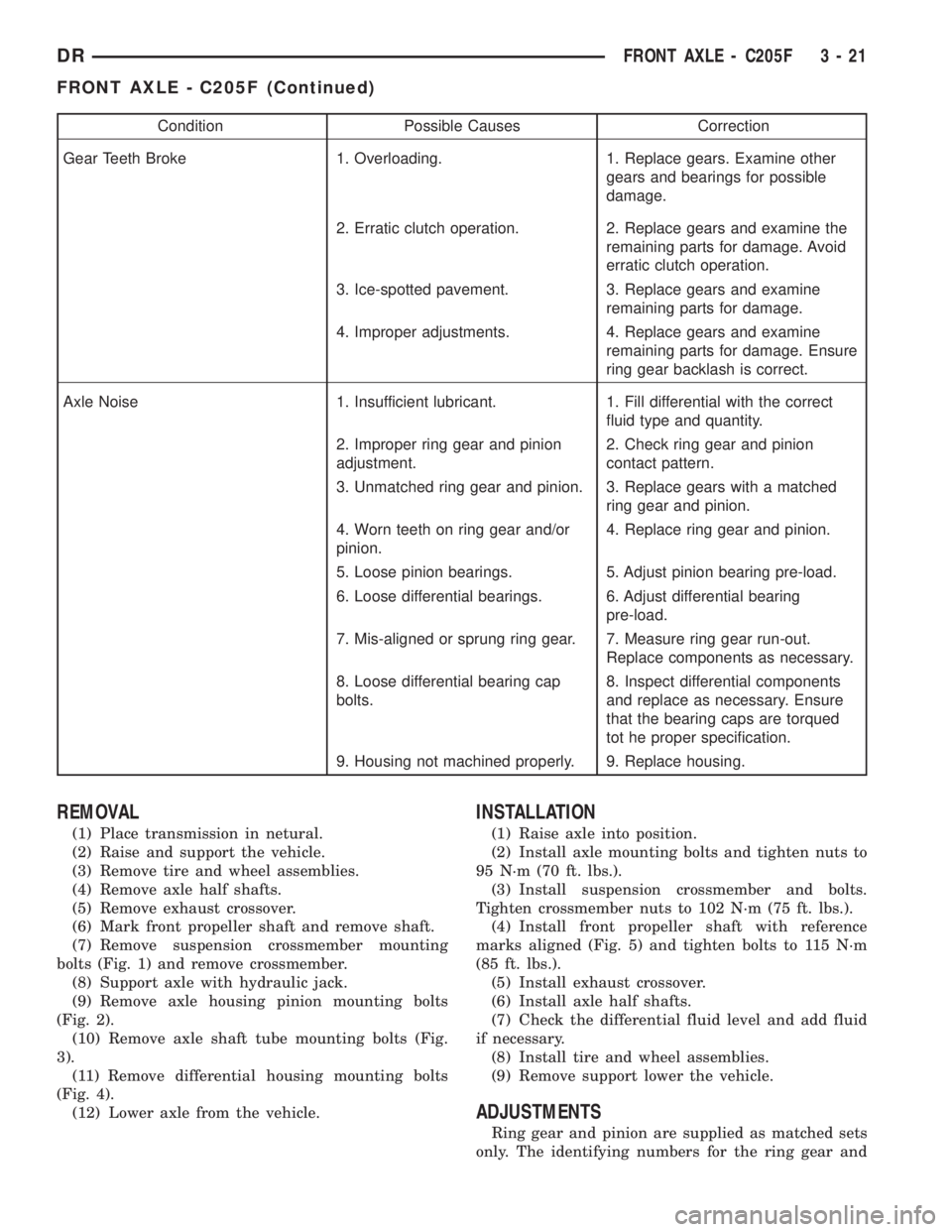
Condition Possible Causes Correction
Gear Teeth Broke 1. Overloading. 1. Replace gears. Examine other
gears and bearings for possible
damage.
2. Erratic clutch operation. 2. Replace gears and examine the
remaining parts for damage. Avoid
erratic clutch operation.
3. Ice-spotted pavement. 3. Replace gears and examine
remaining parts for damage.
4. Improper adjustments. 4. Replace gears and examine
remaining parts for damage. Ensure
ring gear backlash is correct.
Axle Noise 1. Insufficient lubricant. 1. Fill differential with the correct
fluid type and quantity.
2. Improper ring gear and pinion
adjustment.2. Check ring gear and pinion
contact pattern.
3. Unmatched ring gear and pinion. 3. Replace gears with a matched
ring gear and pinion.
4. Worn teeth on ring gear and/or
pinion.4. Replace ring gear and pinion.
5. Loose pinion bearings. 5. Adjust pinion bearing pre-load.
6. Loose differential bearings. 6. Adjust differential bearing
pre-load.
7. Mis-aligned or sprung ring gear. 7. Measure ring gear run-out.
Replace components as necessary.
8. Loose differential bearing cap
bolts.8. Inspect differential components
and replace as necessary. Ensure
that the bearing caps are torqued
tot he proper specification.
9. Housing not machined properly. 9. Replace housing.
REMOVAL
(1) Place transmission in netural.
(2) Raise and support the vehicle.
(3) Remove tire and wheel assemblies.
(4) Remove axle half shafts.
(5) Remove exhaust crossover.
(6) Mark front propeller shaft and remove shaft.
(7) Remove suspension crossmember mounting
bolts (Fig. 1) and remove crossmember.
(8) Support axle with hydraulic jack.
(9) Remove axle housing pinion mounting bolts
(Fig. 2).
(10) Remove axle shaft tube mounting bolts (Fig.
3).
(11) Remove differential housing mounting bolts
(Fig. 4).
(12) Lower axle from the vehicle.
INSTALLATION
(1) Raise axle into position.
(2) Install axle mounting bolts and tighten nuts to
95 N´m (70 ft. lbs.).
(3) Install suspension crossmember and bolts.
Tighten crossmember nuts to 102 N´m (75 ft. lbs.).
(4) Install front propeller shaft with reference
marks aligned (Fig. 5) and tighten bolts to 115 N´m
(85 ft. lbs.).
(5) Install exhaust crossover.
(6) Install axle half shafts.
(7) Check the differential fluid level and add fluid
if necessary.
(8) Install tire and wheel assemblies.
(9) Remove support lower the vehicle.
ADJUSTMENTS
Ring gear and pinion are supplied as matched sets
only. The identifying numbers for the ring gear and
DRFRONT AXLE - C205F 3 - 21
FRONT AXLE - C205F (Continued)
Page 245 of 2895

(6) Adjust brake shoes to drum with brake gauge
(Refer to 5 - BRAKES/PARKING BRAKE/SHOES -
ADJUSTMENTS).
(7) Install the rotor (Refer to 5 - BRAKES/HY-
DRAULIC/MECHANICAL/ROTORS - INSTALLA-
TION).
(8) Install the caliper adapter (Refer to 5 -
BRAKES/HYDRAULIC/MECHANICAL/DISC
BRAKE CALIPER ADAPTER - INSTALLATION).
(9) Install the caliper (Refer to 5 - BRAKES/HY-
DRAULIC/MECHANICAL/DISC BRAKE CALIPERS
- INSTALLATION).
(10) Install wheel and tire assembly.
FLUID
DIAGNOSIS AND TESTING - BRAKE FLUID
CONTAMINATION
Indications of fluid contamination are swollen or
deteriorated rubber parts.
Swollen rubber parts indicate the presence of
petroleum in the brake fluid.
To test for contamination, put a small amount of
drained brake fluid in clear glass jar. If fluid sepa-
rates into layers, there is mineral oil or other fluid
contamination of the brake fluid.
If brake fluid is contaminated, drain and thor-
oughly flush system. Replace master cylinder, propor-
tioning valve, caliper seals, wheel cylinder seals,
Antilock Brakes hydraulic unit and all hydraulic
fluid hoses.
STANDARD PROCEDURE - BRAKE FLUID
LEVEL
Always clean the master cylinder reservoir and
caps before checking fluid level. If not cleaned, dirt
could enter the fluid.
The fluid fill level is indicated on the side of the
master cylinder reservoir (Fig. 33).
The correct fluid level is to the MAX indicator on
the side of the reservoir. If necessary, add fluid to the
proper level.
SPECIFICATIONS
BRAKE FLUID
The brake fluid used in this vehicle must conform
to DOT 3 specifications and SAE J1703 standards.
No other type of brake fluid is recommended or
approved for usage in the vehicle brake system. Use
only Mopar brake fluid or an equivalent from a
tightly sealed container.
CAUTION: Never use reclaimed brake fluid or fluid
from an container which has been left open. An
open container of brake fluid will absorb moisture
from the air and contaminate the fluid.
CAUTION: Never use any type of a petroleum-based
fluid in the brake hydraulic system. Use of such
type fluids will result in seal damage of the vehicle
brake hydraulic system causing a failure of the
vehicle brake system. Petroleum based fluids would
be items such as engine oil, transmission fluid,
power steering fluid, etc.
Fig. 32 CALIPER ADAPTER MOUNT - REAR
1 - CALIPER ADAPTER MOUNT
2 - AXLE TUBE
3 - MOUNTING STUDS
Fig. 33 FLUID LEVEL
1 - FLUID RESERVOIR
2 - MAX LEVEL MARK
5 - 18 BRAKES - BASEDR
DISC BRAKE CALIPER ADAPTER MOUNT (Continued)
Page 255 of 2895

(7) Install the hydraulic booster pressure lines to
the bracket and booster.
(8) Tighten the pressure lines to 41 N´m (30 ft.
lbs.).
NOTE: Inspect o-rings on the pressure line fittings
to insure they are in good condition before installa-
tion. Replace o-rings if necessary.
(9) Install the return hose to the booster.
(10) Bleed base brake system, (Refer to 5 -
BRAKES/HYDRAULIC/MECHANICAL - STAN-
DARD PROCEDURE).
(11) Fill the power steering pump with fluid,
(Refer to 19 - STEERING/PUMP - STANDARD PRO-
CEDURE).
CAUTION: MOPAR (MS-9602) ATF+4 is to be used in
the power steering system. No other power steering
or automatic transmission fluid is to be used in the
system. Damage may result to the power steering
pump and system if any other fluid is used, and do
not overfill.
(12) Bleed the hydraulic booster (Refer to 5 -
BRAKES/HYDRAULIC/MECHANICAL/POWER
BRAKE BOOSTER - STANDARD PROCEDURE).
ROTORS
REMOVAL
REMOVAL - REAR
(1) Raise and support the vehicle
(2) Remove the tire and wheel assembly.
(3) Remove the disc brake caliper, (Refer to 5 -
BRAKES/HYDRAULIC/MECHANICAL/DISC
BRAKE CALIPERS - REMOVAL).
(4) Remove the caliper adapter bolts (Fig.
50).(Refer to 5 - BRAKES/HYDRAULIC/MECHANI-
CAL/DISC BRAKE CALIPER ADAPTER -
REMOVAL)
(5) Remove the retianing clips and rotor assembly
(Fig. 50).
REMOVAL - FRONT
(1) Raise and support the vehicle.
(2) Remove the wheel and tire assembly.
(3) Remove the caliper from the steering knuckle,
(Refer to 5 - BRAKES/HYDRAULIC/MECHANICAL/
DISC BRAKE CALIPERS - REMOVAL) and remove
caliper adapter assembly (Fig. 51).
NOTE: Do not allow brake hose to support caliper
adapter assembly.(4) Remove the rotor from the hub/bearing wheel
studs (Fig. 52) or (Fig. 53).
INSTALLATION
INSTALLATION - REAR
(1) Install the rotor to the axleshaft (Fig. 50).
Fig. 50 REAR ROTOR
1 - ROTOR
2 - CALIPER ADAPTER
3 - CALIPER
Fig. 51 Caliper Adapter Assembly
1 - KNUCKLE
2 - CALIPER
3 - ROTOR
5 - 28 BRAKES - BASEDR
HYDRO-BOOST BRAKE BOOSTER (Continued)
Page 288 of 2895

COOLING
TABLE OF CONTENTS
page page
COOLING
DESCRIPTION
DESCRIPTION - COOLING SYSTEM FLOW
3.7L/4.7L ENGINE......................1
DESCRIPTION - COOLING SYSTEM FLOW -
5.9L ENGINE..........................1
DESCRIPTIONÐCOOLING SYSTEM FLOW -
5.9L DIESEL..........................2
DESCRIPTION - HOSE CLAMPS...........3
OPERATION
OPERATIONÐCOOLING SYSTEM.........3
OPERATIONÐHOSE CLAMPS............5
DIAGNOSIS AND TESTING
DIAGNOSIS AND TESTINGÐON-BOARD
DIAGNOSTICS (OBD)...................5
DIAGNOSIS AND TESTINGÐCOOLING
SYSTEM - TESTING FOR LEAKS..........5
DIAGNOSIS AND TESTING - COOLING
SYSTEM DIESEL ENGINE................7
DIAGNOSIS AND TESTING - PRELIMINARY
CHECKS............................10
STANDARD PROCEDURE
STANDARD PROCEDURE - COOLANT
LEVEL CHECK........................17STANDARD PROCEDURE - COOLING
SYSTEM CLEANING/REVERSE FLUSHING . . 17
STANDARD PROCEDUREÐDRAINING
COOLING SYSTEM 3.7L/4.7L/5.7L ENGINE . . 18
STANDARD PROCEDURE - REFILLING
COOLING SYSTEM 3.7L/4.7L/5.7L ENGINE . . 18
STANDARD PROCEDUREÐDRAINING
COOLING SYSTEM 5.9L/8.0L ENGINE......18
STANDARD PROCEDUREÐREFILLING
COOLING SYSTEM 5.9L/8.0L ENGINE......18
STANDARD PROCEDUREÐDRAINING
COOLING SYSTEM 5.9L DIESEL ENGINE . . . 19
STANDARD PROCEDUREÐREFILLING
COOLING SYSTEM 5.9L DIESEL ENGINE . . . 19
STANDARD PROCEDURE - ADDING
ADDITIONAL COOLANT.................19
SPECIFICATIONS
TORQUE............................20
SPECIFICATIONS -....................20
SPECIAL TOOLS
COOLING...........................20
ACCESSORY DRIVE......................22
ENGINE...............................35
TRANSMISSION.........................72
COOLING
DESCRIPTION
DESCRIPTION - COOLING SYSTEM FLOW
3.7L/4.7L ENGINE
The cooling system regulates engine operating tem-
perature. It allows the engine to reach normal oper-
ating temperature as quickly as possible. It also
maintains normal operating temperature and pre-
vents overheating.
The cooling system provides a means of heating
the passenger compartment and cooling the auto-
matic transmission fluid (if equipped). The cooling
system is pressurized and uses a centrifugal water
pump to circulate coolant through the system and a
coolant deaeration and reserve system that utilizes a
pressurized degas bottle (hot bottle).
An optional factory installed maximum duty cool-
ing package is available on most models. This pack-
age will provide additional cooling capacity forvehicles used under extreme conditions such as
trailer towing in high ambient temperatures (Fig. 1).
DESCRIPTION - COOLING SYSTEM FLOW -
5.9L ENGINE
The cooling system regulates engine operating tem-
perature. It allows the engine to reach normal oper-
ating temperature as quickly as possible. It also
maintains normal operating temperature and pre-
vents overheating.
The cooling system also provides a means of heat-
ing the passenger compartment and cooling the auto-
matic transmission fluid (if equipped). The cooling
system uses a coolant recovery / reserve system that
utilizes an ambient overflow bottle.
An optional factory installed maximum duty cool-
ing package is available on most models. This pack-
age will provide additional cooling capacity for
vehicles used under extreme conditions such as
trailer towing in high ambient temperatures (Fig. 2).
DRCOOLING 7 - 1
Page 293 of 2895
lower inside sealing seat for nicks, cracks, paint, dirt
and solder residue. Inspect the radiator-to- reserve/
overflow tank hose for internal obstructions. Insert a
wire through the hose to be sure it is not obstructed.
Inspect the cams on the outside of the filler neck.
If the cams are damaged, seating of the pressure cap
valve and tester seal will be affected.
Attach pressure tester (7700 or an equivalent) to
radiator filler neck.
Operate the tester pump to apply 103.4 kPa (15
psi) pressure to the system. If the hoses enlarge
excessively or bulges while testing, replace as neces-
sary. Observe the gauge pointer and determine the
condition of the cooling system according to following
criteria:
Holds Steady:If the pointer remains steady for
two minutes, serious coolant leaks are not present in
system. However, there could be an internal leak
that does not appear with normal system test pres-
sure. If it is certain that coolant is being lost and
leaks cannot be detected, inspect for interior leakage
or perform Internal Leakage Test. Refer to INTER-
NAL LEAKAGE INSPECTION.
Drops Slowly:Indicates a small leak or seepage
is occurring. Examine all of the connections for seep-
age or slight leakage with a flashlight. Inspect the
radiator, hoses, gasket edges and heater. Seal the
small leak holes with a Sealer Lubricant (or equiva-
lent). Repair the leak holes and inspect the system
again with pressure applied.Drops Quickly:Indicates that serious leakage is
occurring. Examine the system for external leakage.
If leaks are not visible, inspect for internal leakage.
Large radiator leak holes should be repaired by a
reputable radiator repair shop.
INTERNAL LEAKAGE INSPECTION
Remove the engine oil pan drain plug and drain a
small amount of engine oil. If coolant is present in
the pan, it will drain first because it is heavier than
oil. An alternative method is to operate engine for a
short period to churn the oil. After this is done,
remove the engine dipstick and inspect for water
globules. Also inspect the transmission dipstick for
water globules and transmission fluid cooler for leak-
age.
WARNING: WITH RADIATOR PRESSURE TESTER
TOOL INSTALLED ON RADIATOR, DO NOT ALLOW
PRESSURE TO EXCEED 145 kPa (21 PSI). PRES-
SURE WILL BUILD UP QUICKLY IF A COMBUSTION
LEAK IS PRESENT. TO RELEASE PRESSURE,
ROCK TESTER FROM SIDE TO SIDE. WHEN
REMOVING TESTER, DO NOT TURN TESTER MORE
THAN 1/2 TURN IF SYSTEM IS UNDER PRESSURE.
Operate the engine without the pressure cap on
the radiator until the thermostat opens. Attach a
Pressure Tester to the filler neck. If pressure builds
up quickly it indicates a combustion leak exists. This
is usually the result of a cylinder head gasket leak or
crack in engine. Repair as necessary.
If there is not an immediate pressure increase,
pump the Pressure Tester. Do this until indicated
pressure is within system range of 110 kPa (16 psi).
Fluctuation of the gauge pointer indicates compres-
sion or combustion leakage into cooling system.
Because the vehicle is equipped with a catalytic
converter,do notshort out cylinders to isolate com-
pression leak.
If the needle on dial of the pressure tester does not
fluctuate, race engine a few times to check for an
abnormal amount of coolant or steam. This would be
emitting from exhaust pipe. Coolant or steam from
exhaust pipe may indicate a faulty cylinder head gas-
ket, cracked engine cylinder block or cylinder head.
A convenient check for exhaust gas leakage into
cooling system is provided by a commercially avail-
able Block Leak Check tool. Follow manufacturers
instructions when using this product.
COMBUSTION LEAKAGE TESTÐWITHOUT
PRESSURE TESTER
DO NOT WASTE reusable coolant. If the solution
is clean, drain the coolant into a clean container for
reuse.
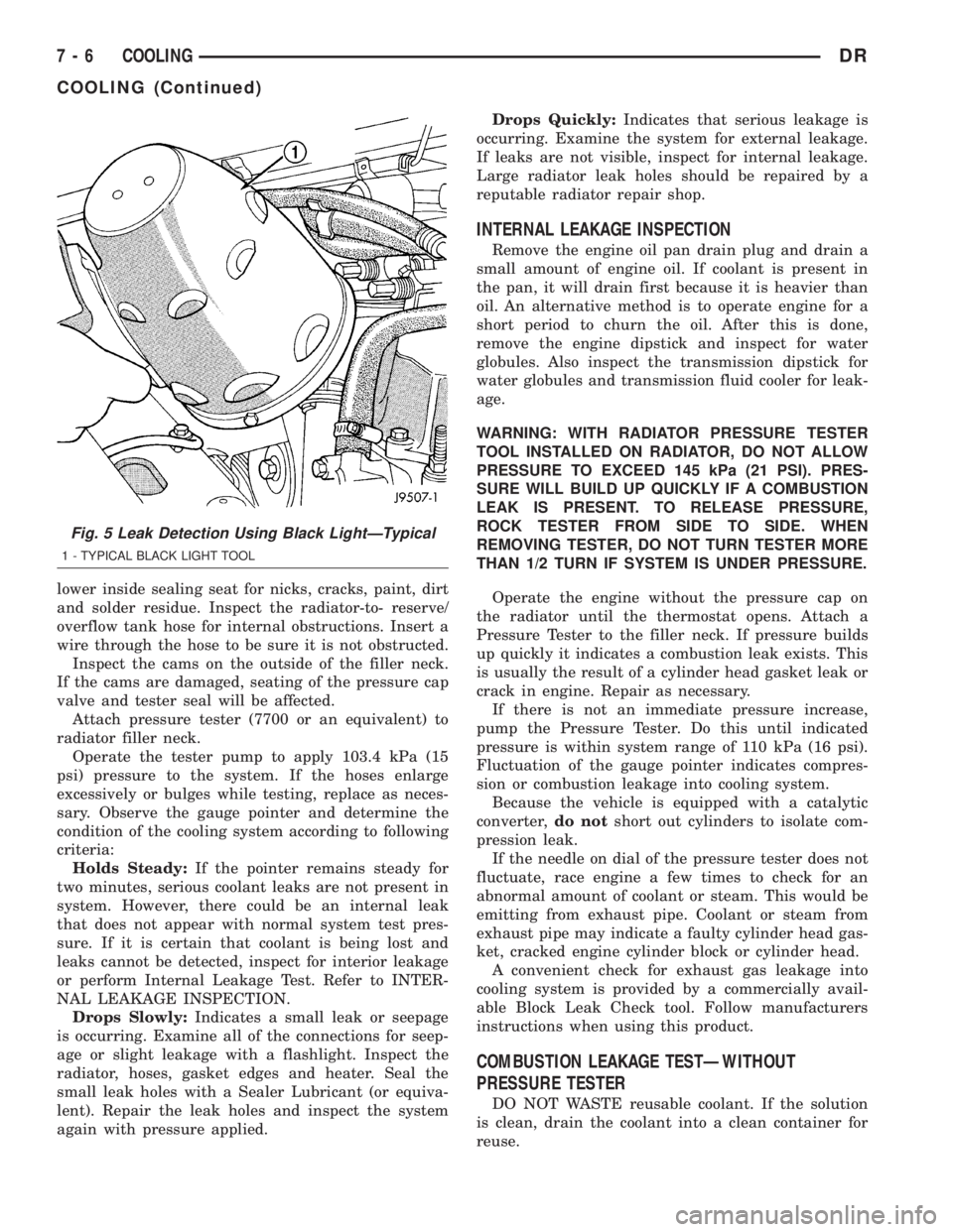
Fig. 5 Leak Detection Using Black LightÐTypical
1 - TYPICAL BLACK LIGHT TOOL
7 - 6 COOLINGDR
COOLING (Continued)
Page 307 of 2895
WARNING: DO NOT REMOVE OR LOOSEN THE
RADIATOR CAP WITH THE COOLING SYSTEM HOT
AND UNDER PRESSURE. SERIOUS BURNS FROM
THE COOLANT OR HIGH PRESSURE STEAM CAN
OCCUR.
For 3.7L / 4.7L/5.9L engines, remove the radiator
cap from the coolant degas bottle to add coolant.
SPECIFICATIONS
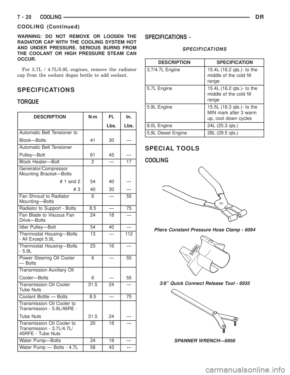
TORQUE
DESCRIPTION N´m Ft. In.
Lbs. Lbs.
Automatic Belt Tensioner to
BlockÐBolts 41 30 Ð
Automatic Belt Tensioner
PulleyÐBolt 61 45 Ð
Block HeaterÐBolt 2 Ð 17
Generator/Compressor
Mounting BracketÐBolts
# 1 and 2 54 40 Ð
# 3 40 30 Ð
Fan Shroud to Radiator
MountingÐBolts6Ð55
Radiator to Support - Bolts 8.5 Ð 75
Fan Blade to Viscous Fan
DriveÐBolts24 18 Ð
Idler PulleyÐBolt 54 40 Ð
Thermostat HousingÐBolts
- All Except 5.9L13 Ð 112
Thermostat HousingÐBolts
- 5.9L23 16 Ð
Power Steering Oil Cooler
Ð Bolts6Ð55
Transmission Auxiliary Oil
CoolerÐBolts 6 Ð 55
Transmission Oil Cooler
Tube Nuts31.5 24 Ð
Coolant Bottle Ð Bolts 8.5 Ð 75
Transmission Oil Cooler to
Transmission - 5.9L/46RE -
Tube Nuts 31.5 24 Ð
Transmission Oil Cooler to
Transmission - 3.7L/4.7L/
45RFE - Tube Nuts20 18 Ð
Water PumpÐBolts 24 18 Ð
Water Pump Ð Bolts - 4.7L 58 43 Ð
SPECIFICATIONS -
SPECIFICATIONS
DESCRIPTION SPECIFICATION
3.7/4.7L Engine 15.4L (16.2 qts.)- to the
middle of the cold fill
range
5.7L Engine 15.4L (16.2 qts.)- to the
middle of the cold fill
range
5.9L Engine 15.5L (16.3 qts.)- to the
MIN mark after 3 warm
up, cool down cycles
8.0L Engine 24L (25.3 qts.)
5.9L Diesel Engine 28L (29.5 qts.)
SPECIAL TOOLS
COOLING
Pliers Constant Pressure Hose Clamp - 6094
3/8º Quick Connect Release Tool - 6935
SPANNER WRENCHÐ6958
7 - 20 COOLINGDR
COOLING (Continued)