2003 DODGE RAM electrical
[x] Cancel search: electricalPage 2629 of 2895
(2) Remove the top cover. (Refer to 23 - BODY/IN-
STRUMENT PANEL/INSTRUMENT PANEL TOP
COVER - REMOVAL)
(3) Disconnect the headliner harness electrical con-
nector at the a-pillar.
(4) Using a trim stick C-4755 or equivalent, from
the notch on the bottom, remove the left side cover.
(Fig. 20)
(5) Remove the steering column. (Refer to 19 -
STEERING/COLUMN - REMOVAL)
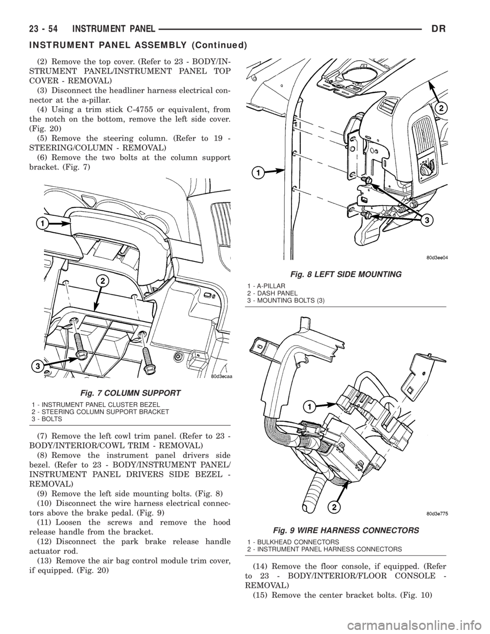
(6) Remove the two bolts at the column support
bracket. (Fig. 7)
(7) Remove the left cowl trim panel. (Refer to 23 -
BODY/INTERIOR/COWL TRIM - REMOVAL)
(8) Remove the instrument panel drivers side
bezel. (Refer to 23 - BODY/INSTRUMENT PANEL/
INSTRUMENT PANEL DRIVERS SIDE BEZEL -
REMOVAL)
(9) Remove the left side mounting bolts. (Fig. 8)
(10) Disconnect the wire harness electrical connec-
tors above the brake pedal. (Fig. 9)
(11) Loosen the screws and remove the hood
release handle from the bracket.
(12) Disconnect the park brake release handle
actuator rod.
(13) Remove the air bag control module trim cover,
if equipped. (Fig. 20)(14) Remove the floor console, if equipped. (Refer
to 23 - BODY/INTERIOR/FLOOR CONSOLE -
REMOVAL)
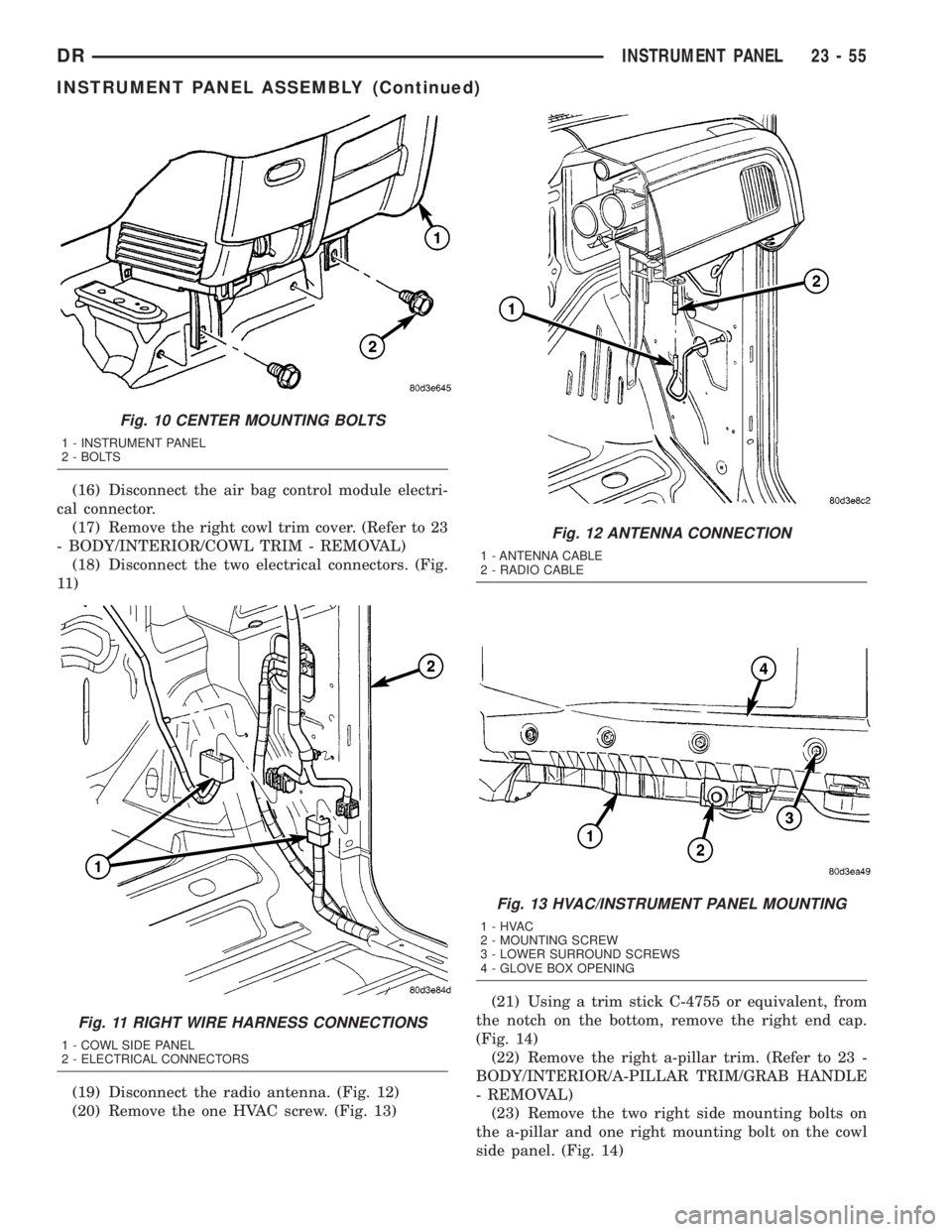
(15) Remove the center bracket bolts. (Fig. 10)
Fig. 7 COLUMN SUPPORT
1 - INSTRUMENT PANEL CLUSTER BEZEL
2 - STEERING COLUMN SUPPORT BRACKET
3 - BOLTS
Fig. 8 LEFT SIDE MOUNTING
1 - A-PILLAR
2 - DASH PANEL
3 - MOUNTING BOLTS (3)
Fig. 9 WIRE HARNESS CONNECTORS
1 - BULKHEAD CONNECTORS
2 - INSTRUMENT PANEL HARNESS CONNECTORS
23 - 54 INSTRUMENT PANELDR
INSTRUMENT PANEL ASSEMBLY (Continued)
Page 2630 of 2895
(16) Disconnect the air bag control module electri-
cal connector.
(17) Remove the right cowl trim cover. (Refer to 23
- BODY/INTERIOR/COWL TRIM - REMOVAL)
(18) Disconnect the two electrical connectors. (Fig.
11 )
(19) Disconnect the radio antenna. (Fig. 12)
(20) Remove the one HVAC screw. (Fig. 13)(21) Using a trim stick C-4755 or equivalent, from
the notch on the bottom, remove the right end cap.
(Fig. 14)
(22) Remove the right a-pillar trim. (Refer to 23 -
BODY/INTERIOR/A-PILLAR TRIM/GRAB HANDLE
- REMOVAL)
(23) Remove the two right side mounting bolts on
the a-pillar and one right mounting bolt on the cowl
side panel. (Fig. 14)
Fig. 10 CENTER MOUNTING BOLTS
1 - INSTRUMENT PANEL
2 - BOLTS
Fig. 11 RIGHT WIRE HARNESS CONNECTIONS
1 - COWL SIDE PANEL
2 - ELECTRICAL CONNECTORS
Fig. 12 ANTENNA CONNECTION
1 - ANTENNA CABLE
2 - RADIO CABLE
Fig. 13 HVAC/INSTRUMENT PANEL MOUNTING
1-HVAC
2 - MOUNTING SCREW
3 - LOWER SURROUND SCREWS
4 - GLOVE BOX OPENING
DRINSTRUMENT PANEL 23 - 55
INSTRUMENT PANEL ASSEMBLY (Continued)
Page 2631 of 2895
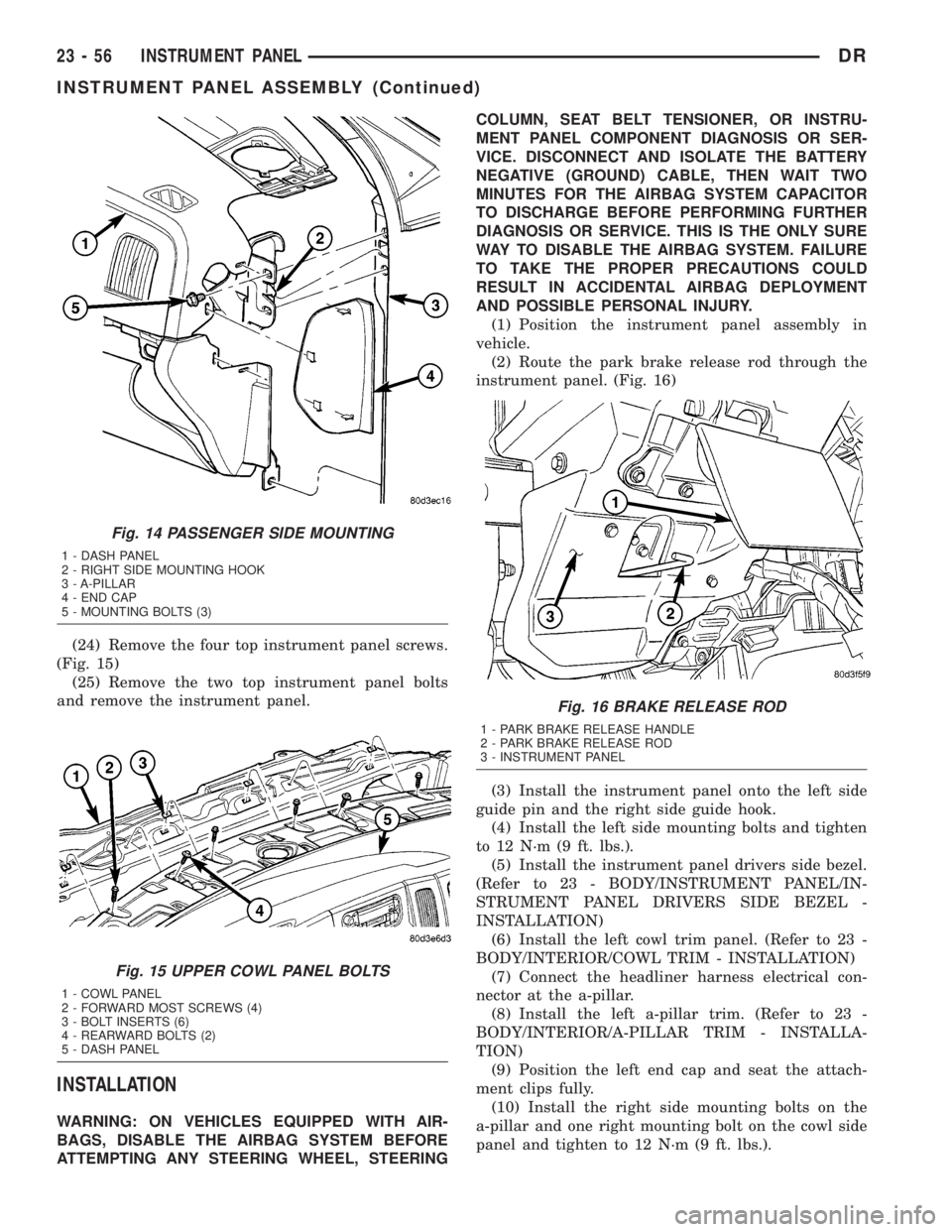
(24) Remove the four top instrument panel screws.
(Fig. 15)
(25) Remove the two top instrument panel bolts
and remove the instrument panel.
INSTALLATION
WARNING: ON VEHICLES EQUIPPED WITH AIR-
BAGS, DISABLE THE AIRBAG SYSTEM BEFORE
ATTEMPTING ANY STEERING WHEEL, STEERINGCOLUMN, SEAT BELT TENSIONER, OR INSTRU-
MENT PANEL COMPONENT DIAGNOSIS OR SER-
VICE. DISCONNECT AND ISOLATE THE BATTERY
NEGATIVE (GROUND) CABLE, THEN WAIT TWO
MINUTES FOR THE AIRBAG SYSTEM CAPACITOR
TO DISCHARGE BEFORE PERFORMING FURTHER
DIAGNOSIS OR SERVICE. THIS IS THE ONLY SURE
WAY TO DISABLE THE AIRBAG SYSTEM. FAILURE
TO TAKE THE PROPER PRECAUTIONS COULD
RESULT IN ACCIDENTAL AIRBAG DEPLOYMENT
AND POSSIBLE PERSONAL INJURY.
(1) Position the instrument panel assembly in
vehicle.
(2) Route the park brake release rod through the
instrument panel. (Fig. 16)
(3) Install the instrument panel onto the left side
guide pin and the right side guide hook.
(4) Install the left side mounting bolts and tighten
to 12 N´m (9 ft. lbs.).
(5) Install the instrument panel drivers side bezel.
(Refer to 23 - BODY/INSTRUMENT PANEL/IN-
STRUMENT PANEL DRIVERS SIDE BEZEL -
INSTALLATION)
(6) Install the left cowl trim panel. (Refer to 23 -
BODY/INTERIOR/COWL TRIM - INSTALLATION)
(7) Connect the headliner harness electrical con-
nector at the a-pillar.
(8) Install the left a-pillar trim. (Refer to 23 -
BODY/INTERIOR/A-PILLAR TRIM - INSTALLA-
TION)
(9) Position the left end cap and seat the attach-
ment clips fully.
(10) Install the right side mounting bolts on the
a-pillar and one right mounting bolt on the cowl side
panel and tighten to 12 N´m (9 ft. lbs.).
Fig. 14 PASSENGER SIDE MOUNTING
1 - DASH PANEL
2 - RIGHT SIDE MOUNTING HOOK
3 - A-PILLAR
4 - END CAP
5 - MOUNTING BOLTS (3)
Fig. 15 UPPER COWL PANEL BOLTS
1 - COWL PANEL
2 - FORWARD MOST SCREWS (4)
3 - BOLT INSERTS (6)
4 - REARWARD BOLTS (2)
5 - DASH PANEL
Fig. 16 BRAKE RELEASE ROD
1 - PARK BRAKE RELEASE HANDLE
2 - PARK BRAKE RELEASE ROD
3 - INSTRUMENT PANEL
23 - 56 INSTRUMENT PANELDR
INSTRUMENT PANEL ASSEMBLY (Continued)
Page 2632 of 2895
(11) Install the right a-pillar trim panel. (Refer to
23 - BODY/INTERIOR/A-PILLAR TRIM - INSTAL-
LATION)
(12) Position the right end cap and seat the
attachment clips fully.
(13) Install the one HVAC mounting screw.
(14) Connect the radio antenna.
(15) Connect the two electrical connectors at the
right cowl panel.
(16) Install the right cowl trim cover. (Refer to 23 -
BODY/INTERIOR/COWL TRIM - INSTALLATION)
(17) Connect the air bag control module electrical
connector.
(18) Install the center bracket bolts and tighten to
12 N´m (9 ft. lbs.).
(19) Install the floor console, if equipped. (Refer to
23 - BODY/INTERIOR/FLOOR CONSOLE - INSTAL-
LATION)
(20) Install the air bag control module cover, if
equipped.
(21) Connect the park brake release handle actua-
tor rod.
(22) Install the hood release handle and tighten
the screws.
(23) Install the two bolts at the column support
bracket and tighten to 14 N´m (10 ft. lbs.).
(24) Install the steering column. (Refer to 19 -
STEERING/COLUMN - INSTALLATION)
(25) Connect the wire harness electrical connectors
above the brake pedal.
(26) Install the two top instrument panel bolts and
tighten to 12 N´m (9 ft. lbs.).
(27) Install the four top instrument panel screws.
(28) Install the instrument panel top cover. (Refer
to 23 - BODY/INSTRUMENT PANEL/INSTRUMENT
PANEL TOP COVER - INSTALLATION)
INSTRUMENT PANEL
HEADLAMP SWITCH BEZEL
REMOVAL
WARNING: ON VEHICLES EQUIPPED WITH AIR-
BAGS, DISABLE THE AIRBAG SYSTEM BEFORE
ATTEMPTING ANY STEERING WHEEL, STEERING
COLUMN, SEAT BELT TENSIONER, OR INSTRU-
MENT PANEL COMPONENT DIAGNOSIS OR SER-
VICE. DISCONNECT AND ISOLATE THE BATTERY
NEGATIVE (GROUND) CABLE, THEN WAIT TWO
MINUTES FOR THE AIRBAG SYSTEM CAPACITOR
TO DISCHARGE BEFORE PERFORMING FURTHER
DIAGNOSIS OR SERVICE. THIS IS THE ONLY SURE
WAY TO DISABLE THE AIRBAG SYSTEM. FAILURE
TO TAKE THE PROPER PRECAUTIONS COULDRESULT IN ACCIDENTAL AIRBAG DEPLOYMENT
AND POSSIBLE PERSONAL INJURY.
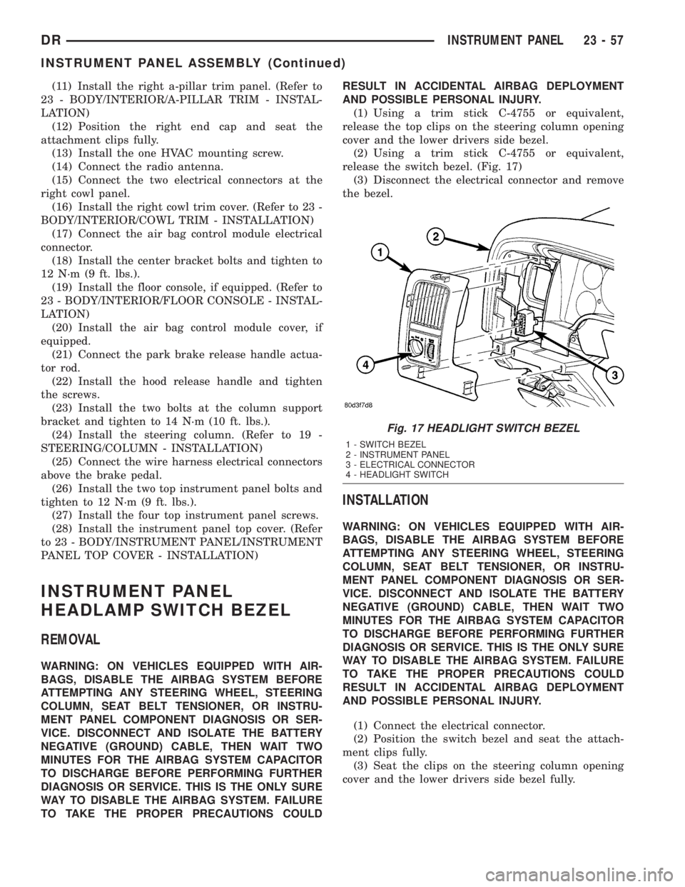
(1) Using a trim stick C-4755 or equivalent,
release the top clips on the steering column opening
cover and the lower drivers side bezel.
(2) Using a trim stick C-4755 or equivalent,
release the switch bezel. (Fig. 17)
(3) Disconnect the electrical connector and remove
the bezel.
INSTALLATION
WARNING: ON VEHICLES EQUIPPED WITH AIR-
BAGS, DISABLE THE AIRBAG SYSTEM BEFORE
ATTEMPTING ANY STEERING WHEEL, STEERING
COLUMN, SEAT BELT TENSIONER, OR INSTRU-
MENT PANEL COMPONENT DIAGNOSIS OR SER-
VICE. DISCONNECT AND ISOLATE THE BATTERY
NEGATIVE (GROUND) CABLE, THEN WAIT TWO
MINUTES FOR THE AIRBAG SYSTEM CAPACITOR
TO DISCHARGE BEFORE PERFORMING FURTHER
DIAGNOSIS OR SERVICE. THIS IS THE ONLY SURE
WAY TO DISABLE THE AIRBAG SYSTEM. FAILURE
TO TAKE THE PROPER PRECAUTIONS COULD
RESULT IN ACCIDENTAL AIRBAG DEPLOYMENT
AND POSSIBLE PERSONAL INJURY.
(1) Connect the electrical connector.
(2) Position the switch bezel and seat the attach-
ment clips fully.
(3) Seat the clips on the steering column opening
cover and the lower drivers side bezel fully.
Fig. 17 HEADLIGHT SWITCH BEZEL
1 - SWITCH BEZEL
2 - INSTRUMENT PANEL
3 - ELECTRICAL CONNECTOR
4 - HEADLIGHT SWITCH
DRINSTRUMENT PANEL 23 - 57
INSTRUMENT PANEL ASSEMBLY (Continued)
Page 2633 of 2895
INSTRUMENT PANEL CENTER
BEZEL
REMOVAL
WARNING: ON VEHICLES EQUIPPED WITH AIR-
BAGS, DISABLE THE AIRBAG SYSTEM BEFORE
ATTEMPTING ANY STEERING WHEEL, STEERING
COLUMN, SEAT BELT TENSIONER, OR INSTRU-
MENT PANEL COMPONENT DIAGNOSIS OR SER-
VICE. DISCONNECT AND ISOLATE THE BATTERY
NEGATIVE (GROUND) CABLE, THEN WAIT TWO
MINUTES FOR THE AIRBAG SYSTEM CAPACITOR
TO DISCHARGE BEFORE PERFORMING FURTHER
DIAGNOSIS OR SERVICE. THIS IS THE ONLY SURE
WAY TO DISABLE THE AIRBAG SYSTEM. FAILURE
TO TAKE THE PROPER PRECAUTIONS COULD
RESULT IN ACCIDENTAL AIRBAG DEPLOYMENT
AND POSSIBLE PERSONAL INJURY.
CAUTION: When removing and installing the center
bezel, use tape or other suitable material to protect
the cupholder and ash receiver from damage.
(1) Disconnect and isolate the negative battery
cable.
(2) Open the ashtray and cup holder.
(3) Remove the one center bezel retaining screw
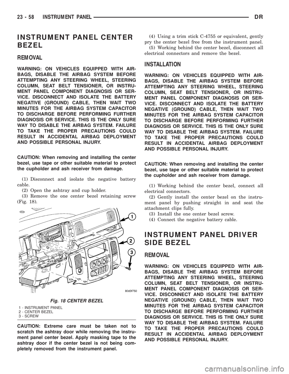
(Fig. 18).
CAUTION: Extreme care must be taken not to
scratch the ashtray door while removing the instru-
ment panel center bezel. Apply masking tape to the
ashtray door if the center bezel is not being com-
pletely removed from the instrument panel.(4) Using a trim stick C-4755 or equivalent, gently
pry the center bezel free from the instrument panel.
(5) Working behind the center bezel, disconnect all
electrical connectors and remove the bezel.INSTALLATION
WARNING: ON VEHICLES EQUIPPED WITH AIR-
BAGS, DISABLE THE AIRBAG SYSTEM BEFORE
ATTEMPTING ANY STEERING WHEEL, STEERING
COLUMN, SEAT BELT TENSIONER, OR INSTRU-
MENT PANEL COMPONENT DIAGNOSIS OR SER-
VICE. DISCONNECT AND ISOLATE THE BATTERY
NEGATIVE (GROUND) CABLE, THEN WAIT TWO
MINUTES FOR THE AIRBAG SYSTEM CAPACITOR
TO DISCHARGE BEFORE PERFORMING FURTHER
DIAGNOSIS OR SERVICE. THIS IS THE ONLY SURE
WAY TO DISABLE THE AIRBAG SYSTEM. FAILURE
TO TAKE THE PROPER PRECAUTIONS COULD
RESULT IN ACCIDENTAL AIRBAG DEPLOYMENT
AND POSSIBLE PERSONAL INJURY.
CAUTION: When removing and installing the center
bezel, use tape or other suitable material to protect
the cupholder and ash receiver from damage.
(1) Working behind the center bezel, connect all
electrical connectors.
(2) Gently install the center bezel on the instru-
ment panel by pushing straight in and seat the
attachment clips fully.
(3) Install the one center bezel screw.
(4) Connect the negative battery cable.
INSTRUMENT PANEL DRIVER
SIDE BEZEL
REMOVAL
WARNING: ON VEHICLES EQUIPPED WITH AIR-
BAGS, DISABLE THE AIRBAG SYSTEM BEFORE
ATTEMPTING ANY STEERING WHEEL, STEERING
COLUMN, SEAT BELT TENSIONER, OR INSTRU-
MENT PANEL COMPONENT DIAGNOSIS OR SER-
VICE. DISCONNECT AND ISOLATE THE BATTERY
NEGATIVE (GROUND) CABLE, THEN WAIT TWO
MINUTES FOR THE AIRBAG SYSTEM CAPACITOR
TO DISCHARGE BEFORE PERFORMING FURTHER
DIAGNOSIS OR SERVICE. THIS IS THE ONLY SURE
WAY TO DISABLE THE AIRBAG SYSTEM. FAILURE
TO TAKE THE PROPER PRECAUTIONS COULD
RESULT IN ACCIDENTAL AIRBAG DEPLOYMENT
AND POSSIBLE PERSONAL INJURY.
Fig. 18 CENTER BEZEL
1 - INSTRUMENT PANEL
2 - CENTER BEZEL
3 - SCREW
23 - 58 INSTRUMENT PANELDR
Page 2634 of 2895
(1) Using a trim stick C-4755 or equivalent, at
notch in the bottom, remove the drivers side endcap.
(2) Remove the drivers side cowl trim panel. (Refer
to 23 - BODY/INTERIOR/COWL TRIM - REMOVAL)
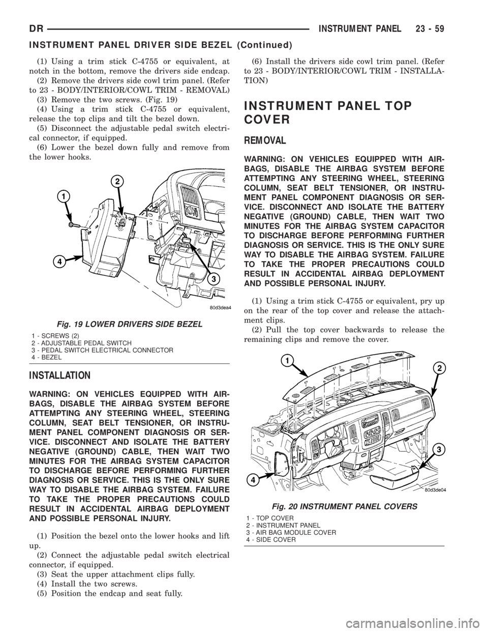
(3) Remove the two screws. (Fig. 19)
(4) Using a trim stick C-4755 or equivalent,
release the top clips and tilt the bezel down.
(5) Disconnect the adjustable pedal switch electri-
cal connector, if equipped.
(6) Lower the bezel down fully and remove from
the lower hooks.
INSTALLATION
WARNING: ON VEHICLES EQUIPPED WITH AIR-
BAGS, DISABLE THE AIRBAG SYSTEM BEFORE
ATTEMPTING ANY STEERING WHEEL, STEERING
COLUMN, SEAT BELT TENSIONER, OR INSTRU-
MENT PANEL COMPONENT DIAGNOSIS OR SER-
VICE. DISCONNECT AND ISOLATE THE BATTERY
NEGATIVE (GROUND) CABLE, THEN WAIT TWO
MINUTES FOR THE AIRBAG SYSTEM CAPACITOR
TO DISCHARGE BEFORE PERFORMING FURTHER
DIAGNOSIS OR SERVICE. THIS IS THE ONLY SURE
WAY TO DISABLE THE AIRBAG SYSTEM. FAILURE
TO TAKE THE PROPER PRECAUTIONS COULD
RESULT IN ACCIDENTAL AIRBAG DEPLOYMENT
AND POSSIBLE PERSONAL INJURY.
(1) Position the bezel onto the lower hooks and lift
up.
(2) Connect the adjustable pedal switch electrical
connector, if equipped.
(3) Seat the upper attachment clips fully.
(4) Install the two screws.
(5) Position the endcap and seat fully.(6) Install the drivers side cowl trim panel. (Refer
to 23 - BODY/INTERIOR/COWL TRIM - INSTALLA-
TION)
INSTRUMENT PANEL TOP
COVER
REMOVAL
WARNING: ON VEHICLES EQUIPPED WITH AIR-
BAGS, DISABLE THE AIRBAG SYSTEM BEFORE
ATTEMPTING ANY STEERING WHEEL, STEERING
COLUMN, SEAT BELT TENSIONER, OR INSTRU-
MENT PANEL COMPONENT DIAGNOSIS OR SER-
VICE. DISCONNECT AND ISOLATE THE BATTERY
NEGATIVE (GROUND) CABLE, THEN WAIT TWO
MINUTES FOR THE AIRBAG SYSTEM CAPACITOR
TO DISCHARGE BEFORE PERFORMING FURTHER
DIAGNOSIS OR SERVICE. THIS IS THE ONLY SURE
WAY TO DISABLE THE AIRBAG SYSTEM. FAILURE
TO TAKE THE PROPER PRECAUTIONS COULD
RESULT IN ACCIDENTAL AIRBAG DEPLOYMENT
AND POSSIBLE PERSONAL INJURY.
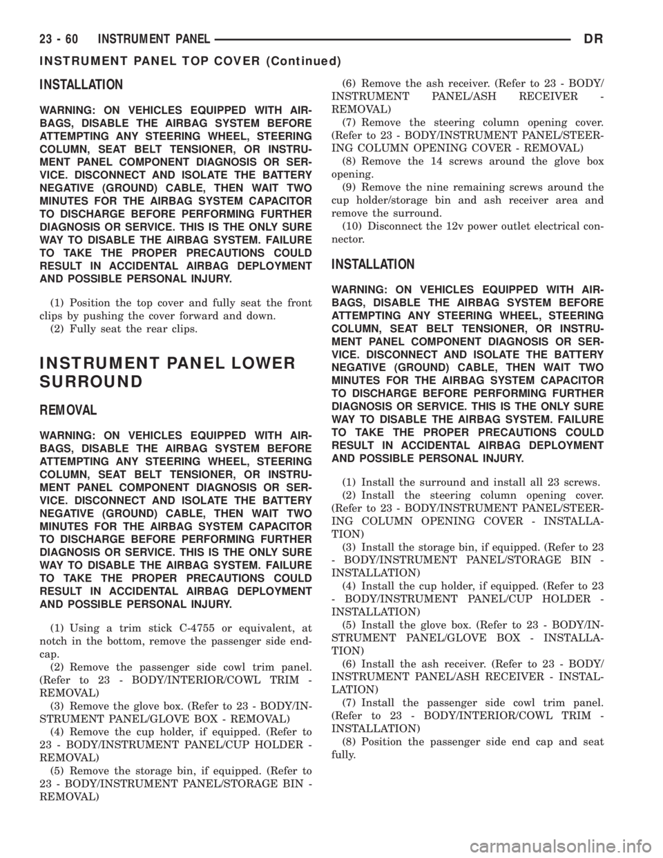
(1) Using a trim stick C-4755 or equivalent, pry up
on the rear of the top cover and release the attach-
ment clips.
(2) Pull the top cover backwards to release the
remaining clips and remove the cover.
Fig. 19 LOWER DRIVERS SIDE BEZEL
1 - SCREWS (2)
2 - ADJUSTABLE PEDAL SWITCH
3 - PEDAL SWITCH ELECTRICAL CONNECTOR
4 - BEZEL
Fig. 20 INSTRUMENT PANEL COVERS
1 - TOP COVER
2 - INSTRUMENT PANEL
3 - AIR BAG MODULE COVER
4 - SIDE COVER
DRINSTRUMENT PANEL 23 - 59
INSTRUMENT PANEL DRIVER SIDE BEZEL (Continued)
Page 2635 of 2895
INSTALLATION
WARNING: ON VEHICLES EQUIPPED WITH AIR-
BAGS, DISABLE THE AIRBAG SYSTEM BEFORE
ATTEMPTING ANY STEERING WHEEL, STEERING
COLUMN, SEAT BELT TENSIONER, OR INSTRU-
MENT PANEL COMPONENT DIAGNOSIS OR SER-
VICE. DISCONNECT AND ISOLATE THE BATTERY
NEGATIVE (GROUND) CABLE, THEN WAIT TWO
MINUTES FOR THE AIRBAG SYSTEM CAPACITOR
TO DISCHARGE BEFORE PERFORMING FURTHER
DIAGNOSIS OR SERVICE. THIS IS THE ONLY SURE
WAY TO DISABLE THE AIRBAG SYSTEM. FAILURE
TO TAKE THE PROPER PRECAUTIONS COULD
RESULT IN ACCIDENTAL AIRBAG DEPLOYMENT
AND POSSIBLE PERSONAL INJURY.
(1) Position the top cover and fully seat the front
clips by pushing the cover forward and down.
(2) Fully seat the rear clips.
INSTRUMENT PANEL LOWER
SURROUND
REMOVAL
WARNING: ON VEHICLES EQUIPPED WITH AIR-
BAGS, DISABLE THE AIRBAG SYSTEM BEFORE
ATTEMPTING ANY STEERING WHEEL, STEERING
COLUMN, SEAT BELT TENSIONER, OR INSTRU-
MENT PANEL COMPONENT DIAGNOSIS OR SER-
VICE. DISCONNECT AND ISOLATE THE BATTERY
NEGATIVE (GROUND) CABLE, THEN WAIT TWO
MINUTES FOR THE AIRBAG SYSTEM CAPACITOR
TO DISCHARGE BEFORE PERFORMING FURTHER
DIAGNOSIS OR SERVICE. THIS IS THE ONLY SURE
WAY TO DISABLE THE AIRBAG SYSTEM. FAILURE
TO TAKE THE PROPER PRECAUTIONS COULD
RESULT IN ACCIDENTAL AIRBAG DEPLOYMENT
AND POSSIBLE PERSONAL INJURY.
(1) Using a trim stick C-4755 or equivalent, at
notch in the bottom, remove the passenger side end-
cap.
(2) Remove the passenger side cowl trim panel.
(Refer to 23 - BODY/INTERIOR/COWL TRIM -
REMOVAL)
(3) Remove the glove box. (Refer to 23 - BODY/IN-
STRUMENT PANEL/GLOVE BOX - REMOVAL)
(4) Remove the cup holder, if equipped. (Refer to
23 - BODY/INSTRUMENT PANEL/CUP HOLDER -
REMOVAL)
(5) Remove the storage bin, if equipped. (Refer to
23 - BODY/INSTRUMENT PANEL/STORAGE BIN -
REMOVAL)(6) Remove the ash receiver. (Refer to 23 - BODY/
INSTRUMENT PANEL/ASH RECEIVER -
REMOVAL)
(7) Remove the steering column opening cover.
(Refer to 23 - BODY/INSTRUMENT PANEL/STEER-
ING COLUMN OPENING COVER - REMOVAL)
(8) Remove the 14 screws around the glove box
opening.
(9) Remove the nine remaining screws around the
cup holder/storage bin and ash receiver area and
remove the surround.
(10) Disconnect the 12v power outlet electrical con-
nector.
INSTALLATION
WARNING: ON VEHICLES EQUIPPED WITH AIR-
BAGS, DISABLE THE AIRBAG SYSTEM BEFORE
ATTEMPTING ANY STEERING WHEEL, STEERING
COLUMN, SEAT BELT TENSIONER, OR INSTRU-
MENT PANEL COMPONENT DIAGNOSIS OR SER-
VICE. DISCONNECT AND ISOLATE THE BATTERY
NEGATIVE (GROUND) CABLE, THEN WAIT TWO
MINUTES FOR THE AIRBAG SYSTEM CAPACITOR
TO DISCHARGE BEFORE PERFORMING FURTHER
DIAGNOSIS OR SERVICE. THIS IS THE ONLY SURE
WAY TO DISABLE THE AIRBAG SYSTEM. FAILURE
TO TAKE THE PROPER PRECAUTIONS COULD
RESULT IN ACCIDENTAL AIRBAG DEPLOYMENT
AND POSSIBLE PERSONAL INJURY.
(1) Install the surround and install all 23 screws.
(2) Install the steering column opening cover.
(Refer to 23 - BODY/INSTRUMENT PANEL/STEER-
ING COLUMN OPENING COVER - INSTALLA-
TION)
(3) Install the storage bin, if equipped. (Refer to 23
- BODY/INSTRUMENT PANEL/STORAGE BIN -
INSTALLATION)
(4) Install the cup holder, if equipped. (Refer to 23
- BODY/INSTRUMENT PANEL/CUP HOLDER -
INSTALLATION)
(5) Install the glove box. (Refer to 23 - BODY/IN-
STRUMENT PANEL/GLOVE BOX - INSTALLA-
TION)
(6) Install the ash receiver. (Refer to 23 - BODY/
INSTRUMENT PANEL/ASH RECEIVER - INSTAL-
LATION)
(7) Install the passenger side cowl trim panel.
(Refer to 23 - BODY/INTERIOR/COWL TRIM -
INSTALLATION)
(8) Position the passenger side end cap and seat
fully.
23 - 60 INSTRUMENT PANELDR
INSTRUMENT PANEL TOP COVER (Continued)
Page 2640 of 2895
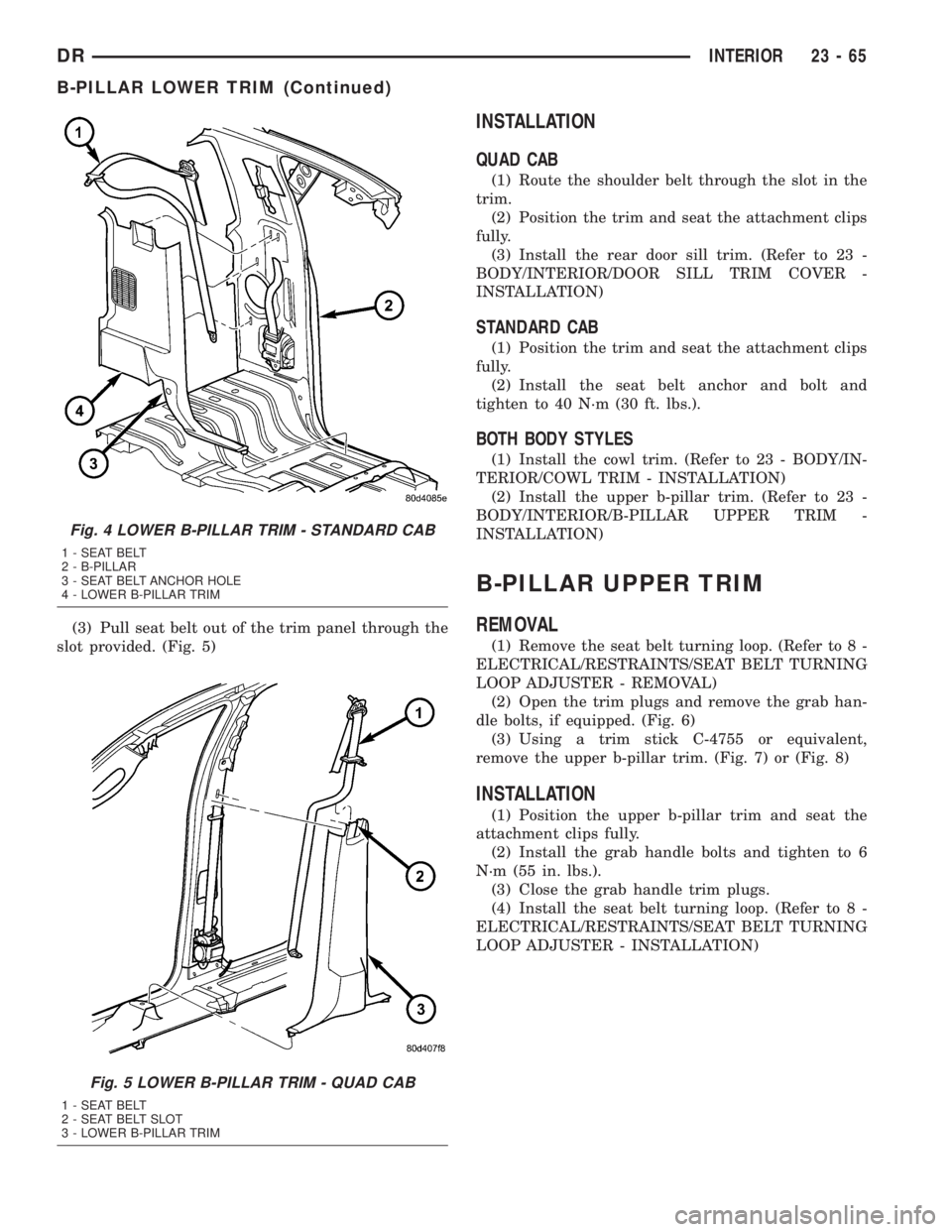
(3) Pull seat belt out of the trim panel through the
slot provided. (Fig. 5)
INSTALLATION
QUAD CAB
(1) Route the shoulder belt through the slot in the
trim.
(2) Position the trim and seat the attachment clips
fully.
(3) Install the rear door sill trim. (Refer to 23 -
BODY/INTERIOR/DOOR SILL TRIM COVER -
INSTALLATION)
STANDARD CAB
(1) Position the trim and seat the attachment clips
fully.
(2) Install the seat belt anchor and bolt and
tighten to 40 N´m (30 ft. lbs.).
BOTH BODY STYLES
(1) Install the cowl trim. (Refer to 23 - BODY/IN-
TERIOR/COWL TRIM - INSTALLATION)
(2) Install the upper b-pillar trim. (Refer to 23 -
BODY/INTERIOR/B-PILLAR UPPER TRIM -
INSTALLATION)
B-PILLAR UPPER TRIM
REMOVAL
(1) Remove the seat belt turning loop. (Refer to 8 -
ELECTRICAL/RESTRAINTS/SEAT BELT TURNING
LOOP ADJUSTER - REMOVAL)
(2) Open the trim plugs and remove the grab han-
dle bolts, if equipped. (Fig. 6)
(3) Using a trim stick C-4755 or equivalent,
remove the upper b-pillar trim. (Fig. 7) or (Fig. 8)
INSTALLATION
(1) Position the upper b-pillar trim and seat the
attachment clips fully.
(2) Install the grab handle bolts and tighten to 6
N´m (55 in. lbs.).
(3) Close the grab handle trim plugs.
(4) Install the seat belt turning loop. (Refer to 8 -
ELECTRICAL/RESTRAINTS/SEAT BELT TURNING
LOOP ADJUSTER - INSTALLATION)
Fig. 4 LOWER B-PILLAR TRIM - STANDARD CAB
1 - SEAT BELT
2 - B-PILLAR
3 - SEAT BELT ANCHOR HOLE
4 - LOWER B-PILLAR TRIM
Fig. 5 LOWER B-PILLAR TRIM - QUAD CAB
1 - SEAT BELT
2 - SEAT BELT SLOT
3 - LOWER B-PILLAR TRIM
DRINTERIOR 23 - 65
B-PILLAR LOWER TRIM (Continued)