2003 DODGE RAM electrical
[x] Cancel search: electricalPage 2525 of 2895
²A flashing operating mode LED for the desired
gear indicates that a shift to that position has been
requested, but all of the driver controllable conditions
have not been met. This is in an attempt to notify
the driver that the transmission needs to be put into
NEUTRAL, the vehicle speed is too great, or some
other condition outlined (other than a diagnostic fail-
ure that would prevent this shift) elsewhere (Refer to
8 - ELECTRICAL/ELECTRONIC CONTROL MOD-
ULES/TRANSFER CASE CONTROL MODULE -
OPERATION) is not met. Note that this flashing will
continue indefinitely until the conditions are eventu-
ally met, or the selector switch position is changed,
or if diagnostic routines no longer allow the
requested shift.
²If the driver attempts to make a shift into trans-
fer case NEUTRAL, and any of the driver controlla-
ble conditions are not met, the request will be
ignored until all of the conditions are met or until
the NEUTRAL select button is released. Additionally
the neutral lamp will flash, or begin to flash while
the button is depressed and operator controllable
conditions are not being met. All of the LED's except
the Neutral will flash if any of the operator control-
lable conditions for shifting are not met while the
Neutral button is depressed. This9toggle9type of fea-
ture is necessary because the TCCM would interpret
another request immediately after the shift into
transfer case NEUTRAL has completed.
²No LED's illuminated indicate a fault in the
transfer case control system.
SHIFT MOTOR
DESCRIPTION
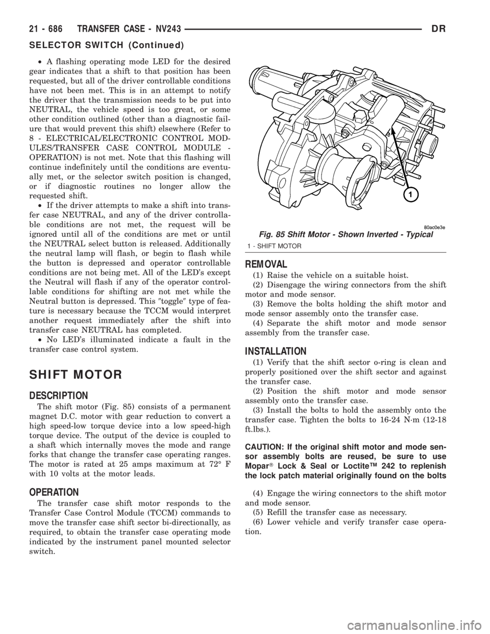
The shift motor (Fig. 85) consists of a permanent
magnet D.C. motor with gear reduction to convert a
high speed-low torque device into a low speed-high
torque device. The output of the device is coupled to
a shaft which internally moves the mode and range
forks that change the transfer case operating ranges.
The motor is rated at 25 amps maximum at 72É F
with 10 volts at the motor leads.
OPERATION
The transfer case shift motor responds to the
Transfer Case Control Module (TCCM) commands to
move the transfer case shift sector bi-directionally, as
required, to obtain the transfer case operating mode
indicated by the instrument panel mounted selector
switch.
REMOVAL
(1) Raise the vehicle on a suitable hoist.
(2) Disengage the wiring connectors from the shift
motor and mode sensor.
(3) Remove the bolts holding the shift motor and
mode sensor assembly onto the transfer case.
(4) Separate the shift motor and mode sensor
assembly from the transfer case.
INSTALLATION
(1) Verify that the shift sector o-ring is clean and
properly positioned over the shift sector and against
the transfer case.
(2) Position the shift motor and mode sensor
assembly onto the transfer case.
(3) Install the bolts to hold the assembly onto the
transfer case. Tighten the bolts to 16-24 N´m (12-18
ft.lbs.).
CAUTION: If the original shift motor and mode sen-
sor assembly bolts are reused, be sure to use
MoparTLock & Seal or LoctiteŸ 242 to replenish
the lock patch material originally found on the bolts
(4) Engage the wiring connectors to the shift motor
and mode sensor.
(5) Refill the transfer case as necessary.
(6) Lower vehicle and verify transfer case opera-
tion.
Fig. 85 Shift Motor - Shown Inverted - Typical
1 - SHIFT MOTOR
21 - 686 TRANSFER CASE - NV243DR
SELECTOR SWITCH (Continued)
Page 2559 of 2895
²A flashing operating mode LED for the desired
gear indicates that a shift to that position has been
requested, but all of the driver controllable conditions
have not been met. This is in an attempt to notify
the driver that the transmission needs to be put into
NEUTRAL, the vehicle speed is too great, or some
other condition outlined (other than a diagnostic fail-
ure that would prevent this shift) elsewhere (Refer to
8 - ELECTRICAL/ELECTRONIC CONTROL MOD-
ULES/TRANSFER CASE CONTROL MODULE -
OPERATION) is not met. Note that this flashing will
continue indefinitely until the conditions are eventu-
ally met, or the selector switch position is changed,
or if diagnostic routines no longer allow the
requested shift.
²If the driver attempts to make a shift into trans-
fer case NEUTRAL, and any of the driver controlla-
ble conditions are not met, the request will be
ignored until all of the conditions are met or until
the NEUTRAL select button is released. Additionally
the neutral lamp will flash, or begin to flash while
the button is depressed and operator controllable
conditions are not being met. All of the LED's except
the Neutral will flash if any of the operator control-
lable conditions for shifting are not met while the
Neutral button is depressed. This9toggle9type of fea-
ture is necessary because the TCCM would interpret
another request immediately after the shift into
transfer case NEUTRAL has completed.
²No LED's illuminated indicate a fault in the
transfer case control system.
SHIFT MOTOR
DESCRIPTION
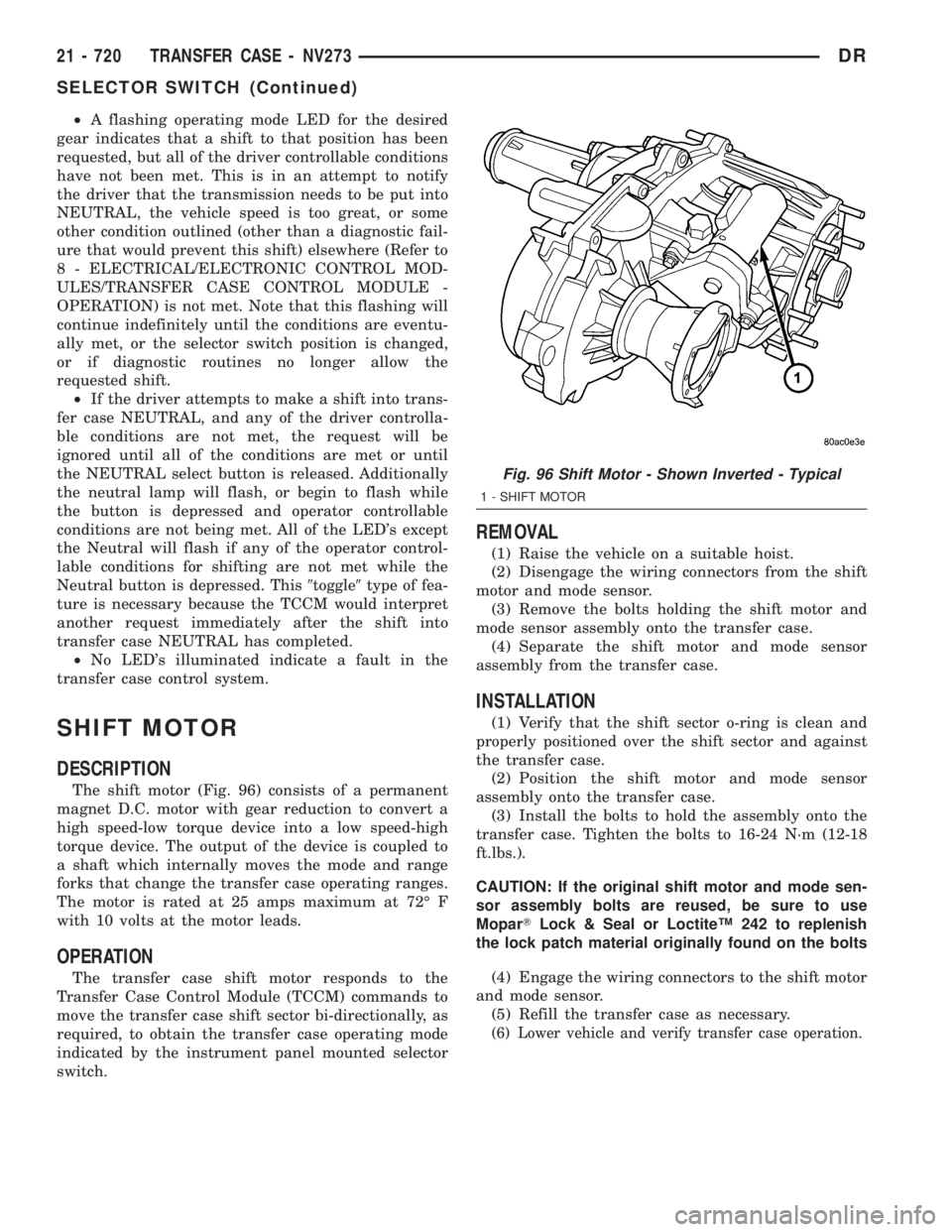
The shift motor (Fig. 96) consists of a permanent
magnet D.C. motor with gear reduction to convert a
high speed-low torque device into a low speed-high
torque device. The output of the device is coupled to
a shaft which internally moves the mode and range
forks that change the transfer case operating ranges.
The motor is rated at 25 amps maximum at 72É F
with 10 volts at the motor leads.
OPERATION
The transfer case shift motor responds to the
Transfer Case Control Module (TCCM) commands to
move the transfer case shift sector bi-directionally, as
required, to obtain the transfer case operating mode
indicated by the instrument panel mounted selector
switch.
REMOVAL
(1) Raise the vehicle on a suitable hoist.
(2) Disengage the wiring connectors from the shift
motor and mode sensor.
(3) Remove the bolts holding the shift motor and
mode sensor assembly onto the transfer case.
(4) Separate the shift motor and mode sensor
assembly from the transfer case.
INSTALLATION
(1) Verify that the shift sector o-ring is clean and
properly positioned over the shift sector and against
the transfer case.
(2) Position the shift motor and mode sensor
assembly onto the transfer case.
(3) Install the bolts to hold the assembly onto the
transfer case. Tighten the bolts to 16-24 N´m (12-18
ft.lbs.).
CAUTION: If the original shift motor and mode sen-
sor assembly bolts are reused, be sure to use
MoparTLock & Seal or LoctiteŸ 242 to replenish
the lock patch material originally found on the bolts
(4) Engage the wiring connectors to the shift motor
and mode sensor.
(5) Refill the transfer case as necessary.
(6) Lower vehicle and verify transfer case operation.
Fig. 96 Shift Motor - Shown Inverted - Typical
1 - SHIFT MOTOR
21 - 720 TRANSFER CASE - NV273DR
SELECTOR SWITCH (Continued)
Page 2576 of 2895
BODY
TABLE OF CONTENTS
page page
BODY
WARNING
SAFETY PRECAUTIONS AND WARNINGS . . . 1
DIAGNOSIS AND TESTING
DIAGNOSIS AND TESTING - WATER LEAKS . 1
DIAGNOSIS AND TESTING - WIND NOISE . . . 2
STANDARD PROCEDURE
STANDARD PROCEDURE - BODY
LUBRICATION.........................3
STANDARD PROCEDURE - HEAT STAKING . . 3
STANDARD PROCEDURE - PLASTIC BODY
PANEL REPAIR........................3
STANDARD PROCEDURE - BUZZ, SQUEAK
& RATTLE...........................11
SPECIFICATIONS - TORQUE..............12SPECIAL TOOLS
BODY..............................14
TAILGATE..............................15
DOOR - FRONT.........................18
DOORS - REAR.........................28
EXTERIOR.............................36
HOOD.................................46
INSTRUMENT PANEL.....................50
INTERIOR..............................63
PAINT.................................74
SEATS................................76
STATIONARY GLASS.....................86
WEATHERSTRIP/SEALS...................91
BODY STRUCTURE......................95
BODY
WARNING
SAFETY PRECAUTIONS AND WARNINGS
WARNING: USE AN OSHA APPROVED BREATHING
FILTER WHEN SPRAYING PAINT OR SOLVENTS IN
A CONFINED AREA. PERSONAL INJURY CAN
RESULT.
²AVOID PROLONGED SKIN CONTACT WITH
PETROLEUM OR ALCOHOL ± BASED CLEANING
SOLVENTS. PERSONAL INJURY CAN RESULT.
²DO NOT STAND UNDER A HOISTED VEHICLE
THAT IS NOT PROPERLY SUPPORTED ON SAFETY
STANDS. PERSONAL INJURY CAN RESULT.
CAUTION: When holes must be drilled or punched
in an inner body panel, verify depth of space to the
outer body panel, electrical wiring, or other compo-
nents. Damage to vehicle can result.
²Do not weld exterior panels unless combustible
material on the interior of vehicle is removed from
the repair area. Fire or hazardous conditions, can
result.
²Always have a fire extinguisher ready for use
when welding.
²Disconnect the negative (-) cable clamp from
the battery when servicing electrical components
that are live when the ignition is OFF. Damage to
electrical system can result.²Do not use abrasive chemicals or compounds
on painted surfaces. Damage to finish can result.
²Do not use harsh alkaline based cleaning sol-
vents on painted or upholstered surfaces. Damage
to finish or color can result.
²Do not hammer or pound on plastic trim panel
when servicing interior trim. Plastic panels can
break.
DIAGNOSIS AND TESTING
DIAGNOSIS AND TESTING - WATER LEAKS
Water leaks can be caused by poor sealing,
improper body component alignment, body seam
porosity, missing plugs, or blocked drain holes. Cen-
trifugal and gravitational force can cause water to
drip from a location away from the actual leak point,
making leak detection difficult. All body sealing
points should be water tight in normal wet-driving
conditions. Water flowing downward from the front of
the vehicle should not enter the passenger or luggage
compartment. Moving sealing surfaces will not
always seal water tight under all conditions. At
times, side glass or door seals will allow water to
enter the passenger compartment during high pres-
sure washing or hard driving rain (severe) condi-
tions. Overcompensating on door or glass
adjustments to stop a water leak that occurs under
severe conditions can cause premature seal wear and
excessive closing or latching effort. After completing
a repair, water test vehicle to verify leak has stopped
before returning vehicle to use.
DRBODY 23 - 1
Page 2579 of 2895

Adhesion Promoter/Surface Modifier:
Adhesion Promoters/Surface Modifiers are required
for certain plastics. All three categories may have
plastics that require the use of adhesion promoter/
surface modifiers. Always follow repair material man-
ufacturer's plastic identification and repair
procedures.
SAFETY PRECAUTION AND WARNINGS
WARNING:
²EYE PROTECTION SHOULD BE USED WHEN
SERVICING COMPONENTS. PERSONAL INJURY
CAN RESULT.
²USE AN OSHA APPROVED BREATHING MASK
WHEN MIXING EPOXY, GRINDING, AND SPRAYING
PAINT OR SOLVENTS IN A CONFINED AREA. PER-
SONAL INJURY CAN RESULT.²AVOID PROLONGED SKIN CONTACT WITH
RESIN, PETROLEUM, OR ALCOHOL BASED SOL-
VENTS. PERSONAL INJURY CAN RESULT.
²DO NOT VENTURE UNDER A HOISTED VEHI-
CLE THAT IS NOT PROPERLY SUPPORTED ON
SAFETY STANDS. PERSONAL INJURY CAN
RESULT.
NOTE:
²When holes must be drilled or cut in body pan-
els, verify locations of internal body components
and electrical wiring. Damage to vehicle can result.
²Do not use abrasive chemicals or compounds
on undamaged painted surfaces around repair
areas. Damage to finish can result.
RIGID, SEMI-RIGID, AND FLEXIBLE PLASTIC PARTS TYPES
CODE FAMILY NAME COMMON TRADE NAME TYPICAL APPLICATION
ASA ACRYLONITRILE STYRENE
ACRYLITELURAN S CONSOLES, GRILLES
ABS ACRYLONITRILE
BUTADIENE STYRENETERLURAN9A9PILLARS, CONSOLES,
GRILLES
ABS/PC ABS/PC ALLOY PULSE, PROLOY,
BAYBLENDDOORS, INSTRUMENT
PANELS
ABS/PVC ABS/PV ALLOY PROLOY, PULSE, LUSTRAN,
CYCLOVINDOOR PANELS, GRILLES,
TRIM
BMC BULK MOLDING
COMPOUNDBMC FENDER EXTENSIONS
EMA EHTYLENE METHYL
ACRYLATE/IONOMERSURLYN, EMA, IONOMER BUMPER GUARDS, PADS
METTON METTON METTON GRILLES, KICK PANELS,
RUNNING BOARDS
MPPO MODIFIED
POLYPHENYLENE OXIDEMPPO SPOILER ASSEMBLY
PA POLYAMID ZYTEL, VYDYNE, PA,
MINLONFENDERS, QUARTER PANELS
PET THERMOPLASTIC
POLYESTERRYNITE TRIM
PBT/PPO PBT/PPO ALLOY GERMAX CLADDINGS
PBTP POLYBUTYLENE
THEREPTHALATEPBT, PBTP, POCAN, VALOX WHEEL COVERS, FENDERS,
GRILLES
PBTP/EEBC POLYBUTYLENE
THEREPTHALATE/EEBC
ALLOYBEXLOY,9M9, PBTP/EEBC FASCIAS, ROCKER PANEL,
MOLDINGS
PC POLYCARBONATE LEXAN, MERLON, CALIBRE,
MAKROLON PCTAIL LIGHT LENSES, IP TRIM,
VALANCE PANELS
23 - 4 BODYDR
BODY (Continued)
Page 2593 of 2895
DOOR - FRONT
TABLE OF CONTENTS
page page
DOOR
REMOVAL.............................18
INSTALLATION.........................18
ADJUSTMENTS
ADJUSTMENT........................19
DOOR GLASS
REMOVAL.............................20
INSTALLATION.........................20
EXTERIOR HANDLE
REMOVAL.............................20
INSTALLATION.........................20
GLASS RUN CHANNEL
REMOVAL.............................21
INSTALLATION.........................21
HINGE
REMOVAL.............................22
INSTALLATION.........................22
INSIDE HANDLE ACTUATOR
REMOVAL.............................22
INSTALLATION.........................22
LATCH
REMOVAL.............................23
INSTALLATION.........................23
ADJUSTMENTS
ADJUSTMENT........................23LATCH STRIKER
REMOVAL.............................24
INSTALLATION.........................24
ADJUSTMENTS
ADJUSTMENT........................24
LOCK CYLINDER
REMOVAL.............................24
INSTALLATION.........................24
TRIM PANEL
REMOVAL.............................24
INSTALLATION.........................24
WATERDAM
REMOVAL.............................25
INSTALLATION.........................25
WINDOW REGULATOR - POWER
REMOVAL.............................25
INSTALLATION.........................25
WINDOW REGULATOR - MANUAL
REMOVAL.............................26
INSTALLATION.........................26
SIDE VIEW MIRROR FLAG
REMOVAL.............................27
INSTALLATION.........................27
DOOR
REMOVAL
(1) Disconnect the door wire harness electrical con-
nector at the A-pillar. (Fig. 1)
(2) Using a grease pencil or equivalent, mark the
outline of the door hinges on the door to aid in instal-
lation.
(3) Support the door with a suitable lifting device.
NOTE: The epoxy bonded washers should not be
seperated from the hinge. If the washers are
removed the door may have to be re-adjusted.
(4) Remove the nuts and bolts attaching the door
hinges to the door.
INSTALLATION
(1) Support the door with a suitable lifting device
and install the door onto the hinges.
(2) Install the washers, if there were removed pre-
viously, nuts and tighten to 28 N´m (21 ft. lbs.).
(3) Connect the electrical connectors.
(4) Adjust the door as necessary. (Refer to 23 -
BODY/DOOR - FRONT/DOOR - ADJUSTMENTS)
23 - 18 DOOR - FRONTDR
Page 2594 of 2895
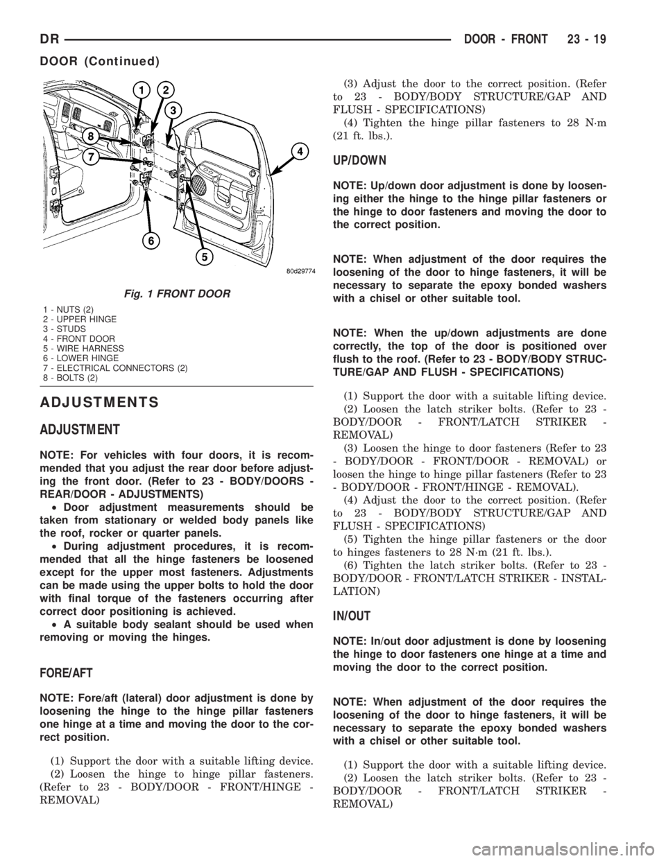
ADJUSTMENTS
ADJUSTMENT
NOTE: For vehicles with four doors, it is recom-
mended that you adjust the rear door before adjust-
ing the front door. (Refer to 23 - BODY/DOORS -
REAR/DOOR - ADJUSTMENTS)
²Door adjustment measurements should be
taken from stationary or welded body panels like
the roof, rocker or quarter panels.
²During adjustment procedures, it is recom-
mended that all the hinge fasteners be loosened
except for the upper most fasteners. Adjustments
can be made using the upper bolts to hold the door
with final torque of the fasteners occurring after
correct door positioning is achieved.
²A suitable body sealant should be used when
removing or moving the hinges.
FORE/AFT
NOTE: Fore/aft (lateral) door adjustment is done by
loosening the hinge to the hinge pillar fasteners
one hinge at a time and moving the door to the cor-
rect position.
(1) Support the door with a suitable lifting device.
(2) Loosen the hinge to hinge pillar fasteners.
(Refer to 23 - BODY/DOOR - FRONT/HINGE -
REMOVAL)(3) Adjust the door to the correct position. (Refer
to 23 - BODY/BODY STRUCTURE/GAP AND
FLUSH - SPECIFICATIONS)
(4) Tighten the hinge pillar fasteners to 28 N´m
(21 ft. lbs.).
UP/DOWN
NOTE: Up/down door adjustment is done by loosen-
ing either the hinge to the hinge pillar fasteners or
the hinge to door fasteners and moving the door to
the correct position.
NOTE: When adjustment of the door requires the
loosening of the door to hinge fasteners, it will be
necessary to separate the epoxy bonded washers
with a chisel or other suitable tool.
NOTE: When the up/down adjustments are done
correctly, the top of the door is positioned over
flush to the roof. (Refer to 23 - BODY/BODY STRUC-
TURE/GAP AND FLUSH - SPECIFICATIONS)
(1) Support the door with a suitable lifting device.
(2) Loosen the latch striker bolts. (Refer to 23 -
BODY/DOOR - FRONT/LATCH STRIKER -
REMOVAL)
(3) Loosen the hinge to door fasteners (Refer to 23
- BODY/DOOR - FRONT/DOOR - REMOVAL) or
loosen the hinge to hinge pillar fasteners (Refer to 23
- BODY/DOOR - FRONT/HINGE - REMOVAL).
(4) Adjust the door to the correct position. (Refer
to 23 - BODY/BODY STRUCTURE/GAP AND
FLUSH - SPECIFICATIONS)
(5) Tighten the hinge pillar fasteners or the door
to hinges fasteners to 28 N´m (21 ft. lbs.).
(6) Tighten the latch striker bolts. (Refer to 23 -
BODY/DOOR - FRONT/LATCH STRIKER - INSTAL-
LATION)
IN/OUT
NOTE: In/out door adjustment is done by loosening
the hinge to door fasteners one hinge at a time and
moving the door to the correct position.
NOTE: When adjustment of the door requires the
loosening of the door to hinge fasteners, it will be
necessary to separate the epoxy bonded washers
with a chisel or other suitable tool.
(1) Support the door with a suitable lifting device.
(2) Loosen the latch striker bolts. (Refer to 23 -
BODY/DOOR - FRONT/LATCH STRIKER -
REMOVAL)
Fig. 1 FRONT DOOR
1 - NUTS (2)
2 - UPPER HINGE
3 - STUDS
4 - FRONT DOOR
5 - WIRE HARNESS
6 - LOWER HINGE
7 - ELECTRICAL CONNECTORS (2)
8 - BOLTS (2)
DRDOOR - FRONT 23 - 19
DOOR (Continued)
Page 2595 of 2895
(3) Loosen the hinge to door fasteners. (Refer to 23
- BODY/DOOR - FRONT/DOOR - REMOVAL)
(4) Adjust the door to the correct position. (Refer
to 23 - BODY/BODY STRUCTURE/GAP AND
FLUSH - SPECIFICATIONS)
(5) Tighten the door to hinges fasteners to 28 N´m
(21 ft. lbs.).
(6) Tighten the latch striker bolts. (Refer to 23 -
BODY/DOOR - FRONT/LATCH STRIKER - INSTAL-
LATION)
DOOR GLASS
REMOVAL
(1) Remove the waterdam. (Refer to 23 - BODY/
DOOR - FRONT/WATERDAM - REMOVAL)
(2) Reinstall the window handle, if equipped.
(3) Remove the window switch from the door trim
panel and reconnect it to the door wire harness, if
equipped.
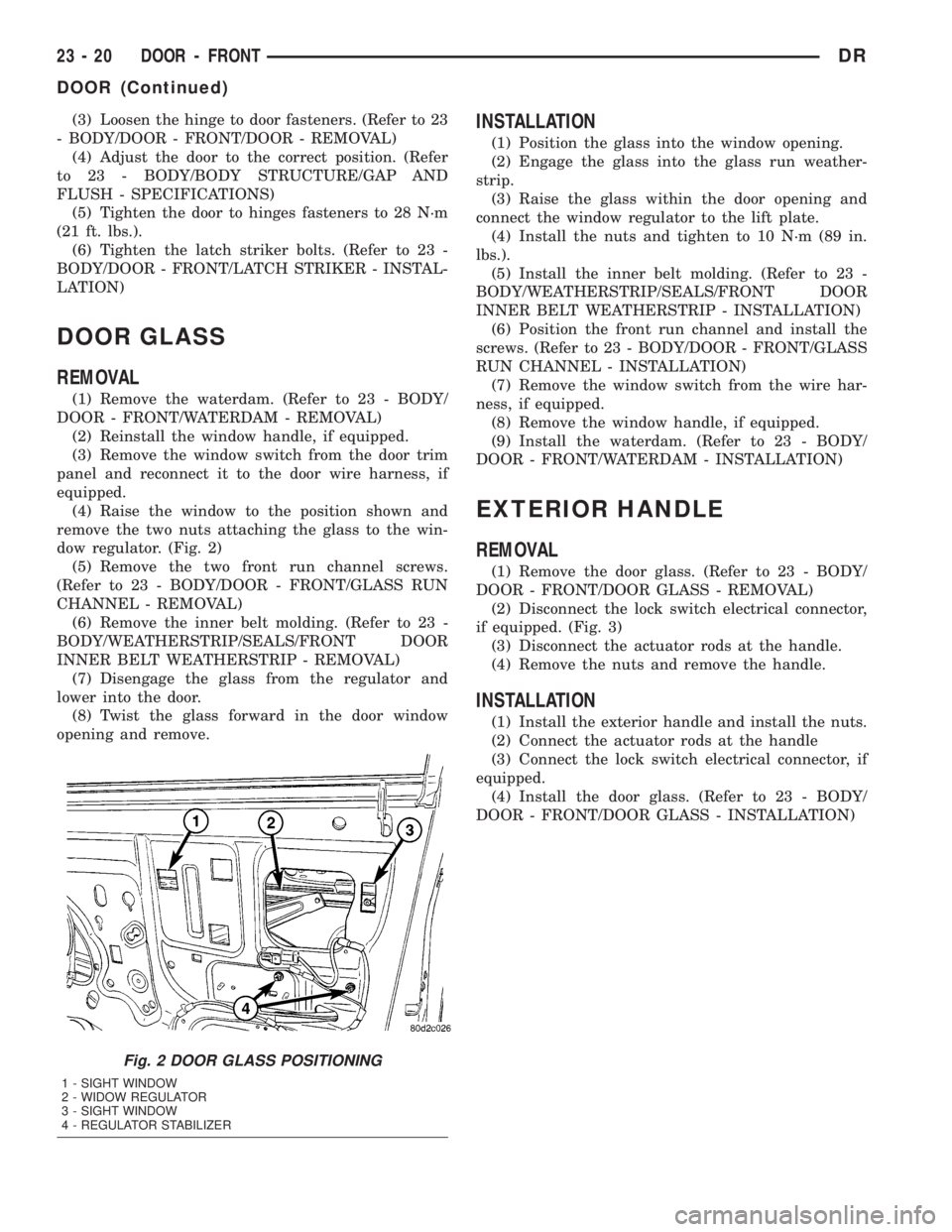
(4) Raise the window to the position shown and
remove the two nuts attaching the glass to the win-
dow regulator. (Fig. 2)
(5) Remove the two front run channel screws.
(Refer to 23 - BODY/DOOR - FRONT/GLASS RUN
CHANNEL - REMOVAL)
(6) Remove the inner belt molding. (Refer to 23 -
BODY/WEATHERSTRIP/SEALS/FRONT DOOR
INNER BELT WEATHERSTRIP - REMOVAL)
(7) Disengage the glass from the regulator and
lower into the door.
(8) Twist the glass forward in the door window
opening and remove.
INSTALLATION
(1) Position the glass into the window opening.
(2) Engage the glass into the glass run weather-
strip.
(3) Raise the glass within the door opening and
connect the window regulator to the lift plate.
(4) Install the nuts and tighten to 10 N´m (89 in.
lbs.).
(5) Install the inner belt molding. (Refer to 23 -
BODY/WEATHERSTRIP/SEALS/FRONT DOOR
INNER BELT WEATHERSTRIP - INSTALLATION)
(6) Position the front run channel and install the
screws. (Refer to 23 - BODY/DOOR - FRONT/GLASS
RUN CHANNEL - INSTALLATION)
(7) Remove the window switch from the wire har-
ness, if equipped.
(8) Remove the window handle, if equipped.
(9) Install the waterdam. (Refer to 23 - BODY/
DOOR - FRONT/WATERDAM - INSTALLATION)
EXTERIOR HANDLE
REMOVAL
(1) Remove the door glass. (Refer to 23 - BODY/
DOOR - FRONT/DOOR GLASS - REMOVAL)
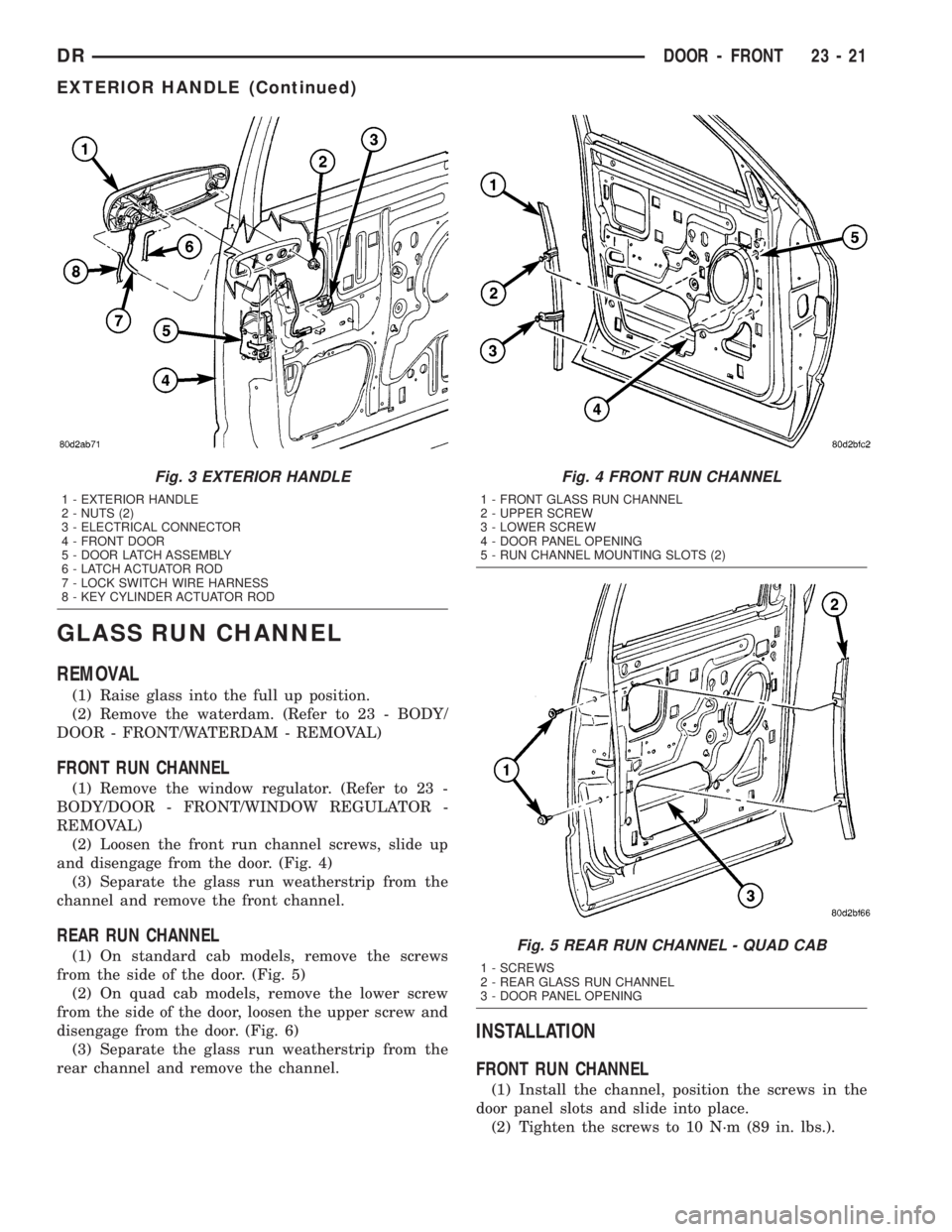
(2) Disconnect the lock switch electrical connector,
if equipped. (Fig. 3)
(3) Disconnect the actuator rods at the handle.
(4) Remove the nuts and remove the handle.
INSTALLATION
(1) Install the exterior handle and install the nuts.
(2) Connect the actuator rods at the handle
(3) Connect the lock switch electrical connector, if
equipped.
(4) Install the door glass. (Refer to 23 - BODY/
DOOR - FRONT/DOOR GLASS - INSTALLATION)
Fig. 2 DOOR GLASS POSITIONING
1 - SIGHT WINDOW
2 - WIDOW REGULATOR
3 - SIGHT WINDOW
4 - REGULATOR STABILIZER
23 - 20 DOOR - FRONTDR
DOOR (Continued)
Page 2596 of 2895
GLASS RUN CHANNEL
REMOVAL
(1) Raise glass into the full up position.
(2) Remove the waterdam. (Refer to 23 - BODY/
DOOR - FRONT/WATERDAM - REMOVAL)
FRONT RUN CHANNEL
(1) Remove the window regulator. (Refer to 23 -
BODY/DOOR - FRONT/WINDOW REGULATOR -
REMOVAL)
(2) Loosen the front run channel screws, slide up
and disengage from the door. (Fig. 4)
(3) Separate the glass run weatherstrip from the
channel and remove the front channel.
REAR RUN CHANNEL
(1) On standard cab models, remove the screws
from the side of the door. (Fig. 5)
(2) On quad cab models, remove the lower screw
from the side of the door, loosen the upper screw and
disengage from the door. (Fig. 6)
(3) Separate the glass run weatherstrip from the
rear channel and remove the channel.
INSTALLATION
FRONT RUN CHANNEL
(1) Install the channel, position the screws in the
door panel slots and slide into place.
(2) Tighten the screws to 10 N´m (89 in. lbs.).
Fig. 3 EXTERIOR HANDLE
1 - EXTERIOR HANDLE
2 - NUTS (2)
3 - ELECTRICAL CONNECTOR
4 - FRONT DOOR
5 - DOOR LATCH ASSEMBLY
6 - LATCH ACTUATOR ROD
7 - LOCK SWITCH WIRE HARNESS
8 - KEY CYLINDER ACTUATOR ROD
Fig. 4 FRONT RUN CHANNEL
1 - FRONT GLASS RUN CHANNEL
2 - UPPER SCREW
3 - LOWER SCREW
4 - DOOR PANEL OPENING
5 - RUN CHANNEL MOUNTING SLOTS (2)
Fig. 5 REAR RUN CHANNEL - QUAD CAB
1 - SCREWS
2 - REAR GLASS RUN CHANNEL
3 - DOOR PANEL OPENING
DRDOOR - FRONT 23 - 21
EXTERIOR HANDLE (Continued)