Page 2610 of 2895
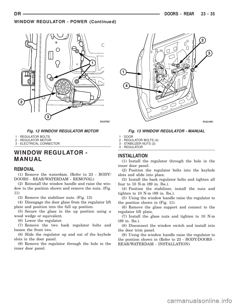
WINDOW REGULATOR -
MANUAL
REMOVAL
(1) Remove the waterdam. (Refer to 23 - BODY/
DOORS - REAR/WATERDAM - REMOVAL)
(2) Reinstall the window handle and raise the win-
dow to the position shown and remove the nuts. (Fig.
11 )
(3) Remove the stabilizer nuts. (Fig. 13)
(4) Disengage the door glass from the regulator lift
plate and position into the full up position.
(5) Secure the glass in the up position using a
wood wedge or equivalent.
(6) Lower the regulator.
(7) Remove the two back regulator bolts and
loosen the front two.
(8) Slide the regulator up and out of the keyhole
slots in the door panel.
(9) Remove the regulator through the hole in the
inner door panel.
INSTALLATION
(1) Install the regulator through the hole in the
inner door panel.
(2) Position the regulator bolts into the keyhole
slots and slide into place.
(3) Install the back regulator bolts and tighten all
four to 10 N´m (89 in. lbs.).
(4) Position the stabilizer, install the nuts and
tighten to 10 N´m (89 in. lbs.).
(5) Using the window handle raise the regulator to
the position shown in (Fig. 11).
(6) Remove the glass support and connect to the
regulator lift plate.
(7) Install the glass nuts and tighten to 10 N´m
(89 in. lbs.).
(8) Disconnect the window switch and install into
the door trim panel.
(9) Using the window handle raise the regulator to
the position shown in (Refer to 23 - BODY/DOORS -
REAR/WATERDAM - INSTALLATION)
Fig. 12 WINDOW REGULATOR MOTOR
1 - REGULATOR BOLTS
2 - REGULATOR MOTOR
3 - ELECTRICAL CONNECTOR.
Fig. 13 WINDOW REGULATOR - MANUAL
1 - DOOR
2 - REGULATOR BOLTS (4)
3 - STABILIZER NUTS (2)
4 - REGULATOR
DRDOORS - REAR 23 - 35
WINDOW REGULATOR - POWER (Continued)
Page 2614 of 2895
FRONT FENDER
REMOVAL
(1) Remove the antenna, if equipped. (Refer to 8 -
ELECTRICAL/AUDIO/ANTENNA BODY & CABLE -
REMOVAL)
(2) Remove the battery tray, if required. (Refer to 8
- ELECTRICAL/BATTERY SYSTEM/TRAY -
REMOVAL)
(3) Remove the cowl grille. (Refer to 23 - BODY/
EXTERIOR/COWL GRILLE - REMOVAL)
(4) Remove the headlamp unit. (Refer to 8 - ELEC-
TRICAL/LAMPS/LIGHTING - EXTERIOR/HEAD-
LAMP UNIT - REMOVAL)
(5) Remove the wheelhouse splash shield. (Refer to
23 - BODY/EXTERIOR/FRONT WHEELHOUSE
SPLASH SHIELD - REMOVAL)
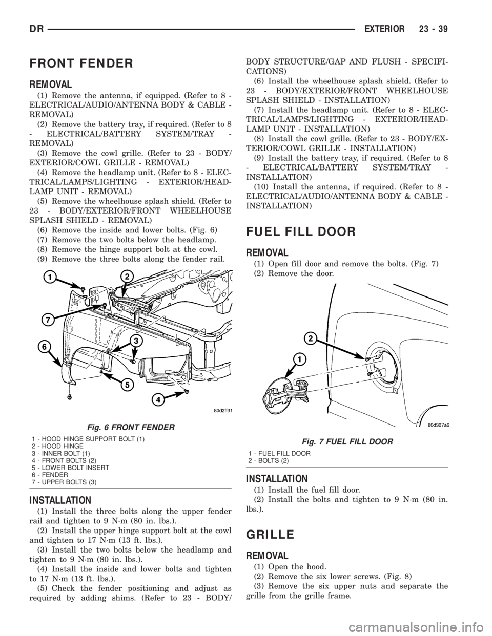
(6) Remove the inside and lower bolts. (Fig. 6)
(7) Remove the two bolts below the headlamp.
(8) Remove the hinge support bolt at the cowl.
(9) Remove the three bolts along the fender rail.
INSTALLATION
(1) Install the three bolts along the upper fender
rail and tighten to 9 N´m (80 in. lbs.).
(2) Install the upper hinge support bolt at the cowl
and tighten to 17 N´m (13 ft. lbs.).
(3) Install the two bolts below the headlamp and
tighten to 9 N´m (80 in. lbs.).
(4) Install the inside and lower bolts and tighten
to 17 N´m (13 ft. lbs.).
(5) Check the fender positioning and adjust as
required by adding shims. (Refer to 23 - BODY/BODY STRUCTURE/GAP AND FLUSH - SPECIFI-
CATIONS)
(6) Install the wheelhouse splash shield. (Refer to
23 - BODY/EXTERIOR/FRONT WHEELHOUSE
SPLASH SHIELD - INSTALLATION)
(7) Install the headlamp unit. (Refer to 8 - ELEC-
TRICAL/LAMPS/LIGHTING - EXTERIOR/HEAD-
LAMP UNIT - INSTALLATION)
(8) Install the cowl grille. (Refer to 23 - BODY/EX-
TERIOR/COWL GRILLE - INSTALLATION)
(9) Install the battery tray, if required. (Refer to 8
- ELECTRICAL/BATTERY SYSTEM/TRAY -
INSTALLATION)
(10) Install the antenna, if required. (Refer to 8 -
ELECTRICAL/AUDIO/ANTENNA BODY & CABLE -
INSTALLATION)
FUEL FILL DOOR
REMOVAL
(1) Open fill door and remove the bolts. (Fig. 7)
(2) Remove the door.
INSTALLATION
(1) Install the fuel fill door.
(2) Install the bolts and tighten to 9 N´m (80 in.
lbs.).
GRILLE
REMOVAL
(1) Open the hood.
(2) Remove the six lower screws. (Fig. 8)
(3) Remove the six upper nuts and separate the
grille from the grille frame.
Fig. 6 FRONT FENDER
1 - HOOD HINGE SUPPORT BOLT (1)
2 - HOOD HINGE
3 - INNER BOLT (1)
4 - FRONT BOLTS (2)
5 - LOWER BOLT INSERT
6 - FENDER
7 - UPPER BOLTS (3)Fig. 7 FUEL FILL DOOR
1 - FUEL FILL DOOR
2 - BOLTS (2)
DREXTERIOR 23 - 39
Page 2615 of 2895
INSTALLATION
(1) Position the grille onto the grille frame.
(2) Install the six upper nuts.
(3) Install the six lower screws.
GRILLE FRAME
REMOVAL
(1) Remove the grille. (Refer to 23 - BODY/EXTE-
RIOR/GRILLE - REMOVAL)
(2) Remove the screws and remove the grille
frame. (Fig. 9)
INSTALLATION
(1) Install the grille frame and install the six
screws.
(2) Install the grille. (Refer to 23 - BODY/EXTERI-
OR/GRILLE - INSTALLATION)
FRONT WHEELHOUSE
SPLASH SHIELD
REMOVAL
(1) Remove the three screws at the fender. (Fig.
10)(2) Remove the electrical connector push pin fas-
tener.
(3) Remove the five inside screws and remove the
splash shield.
Fig. 8 GRILLE
1 - NUTS (6)
2 - HOOD
3 - GRILLE
4 - GRILLE FRAME
5 - SCREWS (6)
Fig. 9 GRILLE FRAME
1 - HOOD
2 - GRILLE FRAME
3 - SCREWS (6)
Fig. 10 FRONT SPLASH SHIELD
1 - FENDER RAIL
2 - FENDER
3 - SCREWS (8)
4 - WHEELHOUSE SPLASH SHIELD
23 - 40 EXTERIORDR
GRILLE (Continued)
Page 2616 of 2895
INSTALLATION
(1) Install the splash shield and position the front
edge into the support bracket on the bumper.
(2) Install the five inner screws.
(3) Install the three screws at the fender.
(4) Install the electrical connector push pin fas-
tener.
REAR WHEELHOUSE SPLASH
SHIELD
REMOVAL
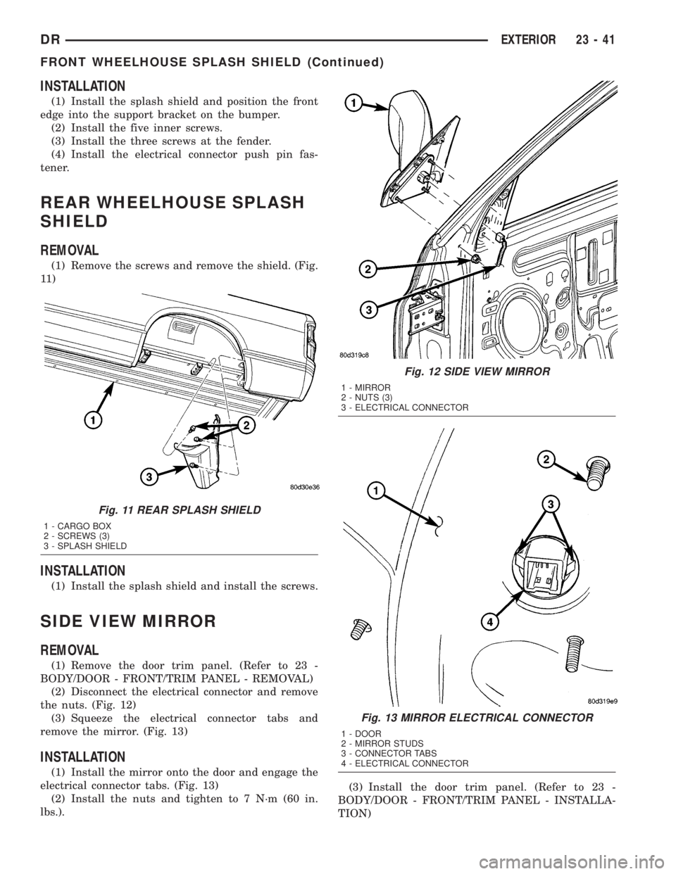
(1) Remove the screws and remove the shield. (Fig.
11 )
INSTALLATION
(1) Install the splash shield and install the screws.
SIDE VIEW MIRROR
REMOVAL
(1) Remove the door trim panel. (Refer to 23 -
BODY/DOOR - FRONT/TRIM PANEL - REMOVAL)
(2) Disconnect the electrical connector and remove
the nuts. (Fig. 12)
(3) Squeeze the electrical connector tabs and
remove the mirror. (Fig. 13)
INSTALLATION
(1) Install the mirror onto the door and engage the
electrical connector tabs. (Fig. 13)
(2) Install the nuts and tighten to 7 N´m (60 in.
lbs.).(3) Install the door trim panel. (Refer to 23 -
BODY/DOOR - FRONT/TRIM PANEL - INSTALLA-
TION)
Fig. 11 REAR SPLASH SHIELD
1 - CARGO BOX
2 - SCREWS (3)
3 - SPLASH SHIELD
Fig. 12 SIDE VIEW MIRROR
1 - MIRROR
2 - NUTS (3)
3 - ELECTRICAL CONNECTOR
Fig. 13 MIRROR ELECTRICAL CONNECTOR
1 - DOOR
2 - MIRROR STUDS
3 - CONNECTOR TABS
4 - ELECTRICAL CONNECTOR
DREXTERIOR 23 - 41
FRONT WHEELHOUSE SPLASH SHIELD (Continued)
Page 2617 of 2895
UPPER RADIATOR
CROSSMEMBER
REMOVAL
(1) Remove the hood latch. (Refer to 23 - BODY/
HOOD/LATCH - REMOVAL)
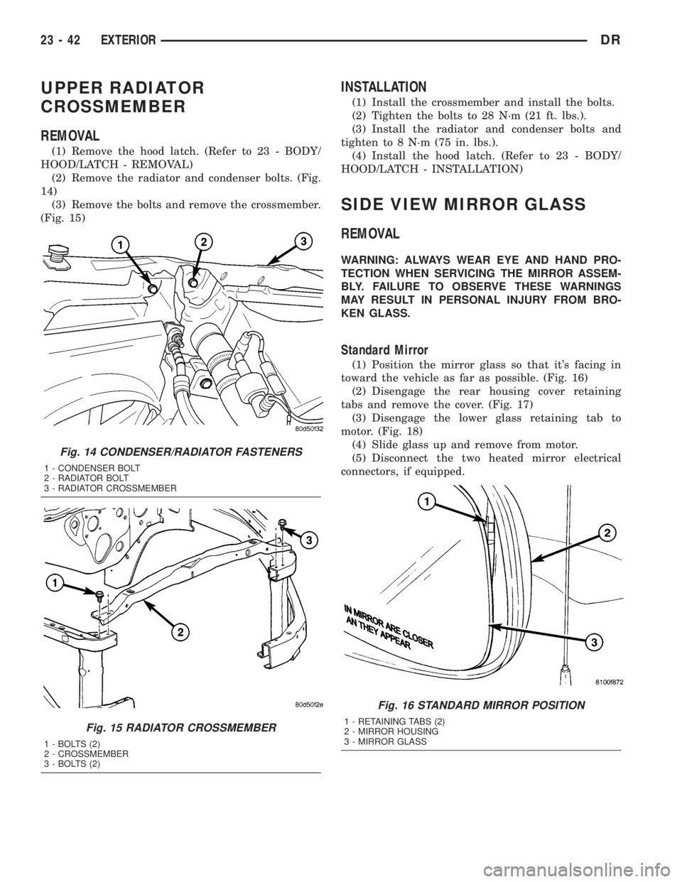
(2) Remove the radiator and condenser bolts. (Fig.
14)
(3) Remove the bolts and remove the crossmember.
(Fig. 15)
INSTALLATION
(1) Install the crossmember and install the bolts.
(2) Tighten the bolts to 28 N´m (21 ft. lbs.).
(3) Install the radiator and condenser bolts and
tighten to 8 N´m (75 in. lbs.).
(4) Install the hood latch. (Refer to 23 - BODY/
HOOD/LATCH - INSTALLATION)
SIDE VIEW MIRROR GLASS
REMOVAL
WARNING: ALWAYS WEAR EYE AND HAND PRO-
TECTION WHEN SERVICING THE MIRROR ASSEM-
BLY. FAILURE TO OBSERVE THESE WARNINGS
MAY RESULT IN PERSONAL INJURY FROM BRO-
KEN GLASS.
Standard Mirror
(1) Position the mirror glass so that it's facing in
toward the vehicle as far as possible. (Fig. 16)
(2) Disengage the rear housing cover retaining
tabs and remove the cover. (Fig. 17)
(3) Disengage the lower glass retaining tab to
motor. (Fig. 18)
(4) Slide glass up and remove from motor.
(5) Disconnect the two heated mirror electrical
connectors, if equipped.
Fig. 14 CONDENSER/RADIATOR FASTENERS
1 - CONDENSER BOLT
2 - RADIATOR BOLT
3 - RADIATOR CROSSMEMBER
Fig. 15 RADIATOR CROSSMEMBER
1 - BOLTS (2)
2 - CROSSMEMBER
3 - BOLTS (2)
Fig. 16 STANDARD MIRROR POSITION
1 - RETAINING TABS (2)
2 - MIRROR HOUSING
3 - MIRROR GLASS
23 - 42 EXTERIORDR
Page 2618 of 2895
Tow Package Mirror
(1) Position the mirror in the out position. (Fig. 19)
(2) Release the retaining clip and separate the
glass.
(3) Disconnect the four heated glass electrical con-
nectors, if equipped. (Fig. 20)
Fig. 17 STANDARD MIRROR HOUSING COVER
1 - MIRROR HOUSING COVER
2 - RETAINING TABS (3)
Fig. 18 STANDARD MIRROR RETAINING TAB
1 - MIRROR ASSEMBLY
2 - MIRROR GLASS LOWER RETAINING TAB
Fig. 19 TOW PACKAGE MIRROR POSITION
1 - MIRROR HOUSING ASSEMBLY
2 - MIRROR GLASS RETAINING CLIP
3 - MIRROR GLASS
Fig. 20 TOW PACKAGE MIRROR GLASS
1 - HEATED GLASS ELECTRICAL CONNECTORS (IF EQUIPPED)
2 - MIRROR GLASS
3 - RETAINING CLIP
DREXTERIOR 23 - 43
SIDE VIEW MIRROR GLASS (Continued)
Page 2619 of 2895
INSTALLATION
Standard Mirror
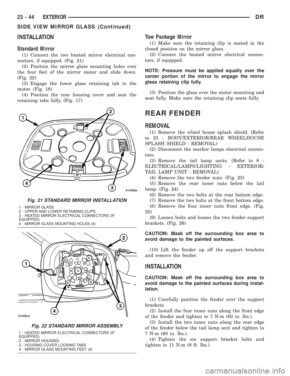
(1) Connect the two heated mirror electrical con-
nectors, if equipped. (Fig. 21)
(2) Position the mirror glass mounting holes over
the four feet of the mirror motor and slide down.
(Fig. 22)
(3) Engage the lower glass retaining tab to the
motor. (Fig. 18)
(4) Position the rear housing cover and seat the
retaining tabs fully. (Fig. 17)
Tow Package Mirror
(1) Make sure the retaining clip is seated in the
closed position on the mirror glass.
(2) Connect the heated mirror electrical connec-
tors, if equipped.
NOTE: Pressure must be applied equally over the
center portion of the mirror to engage the mirror
glass retaining clip fully.
(3) Position the glass over the motor mounting and
seat fully. Make sure the retaining clip seats fully.
REAR FENDER
REMOVAL
(1) Remove the wheel house splash shield. (Refer
to 23 - BODY/EXTERIOR/REAR WHEELHOUSE
SPLASH SHIELD - REMOVAL)
(2) Disconnect the marker lamps electrical connec-
tors.
(3) Remove the tail lamp units. (Refer to 8 -
ELECTRICAL/LAMPS/LIGHTING - EXTERIOR/
TAIL LAMP UNIT - REMOVAL)
(4) Remove the two fender nuts. (Fig. 23)
(5) Remove the rear inner nuts below the tail
lamp. (Fig. 24)
(6) Remove the two bolts at the rear bottom edge.
(7) Remove the two bolts at the front bottom edge.
(8) Remove the four inner nuts front edge. (Fig.
25)
(9) Loosen bolts and loosen the two fender support
brackets. (Fig. 26)
CAUTION: Mask off the surrounding box area to
avoid damage to the painted surfaces.
(10) Lift the fender up off the support brackets
and remove the fender.
INSTALLATION
CAUTION: Mask off the surrounding box area to
avoid damage to the painted surfaces during instal-
lation.
(1) Carefully position the fender over the support
brackets.
(2) Install the four inner nuts along the front edge
of the fender and tighten to 7 N´m (60 in. lbs.).
(3) Install the two inner nuts along the rear edge
of the fender below the tail lamp unit and tighten to
7 N´m (60 in. lbs.).
(4) Tighten the six support bracket bolts and
tighten to 11 N´m (8 ft. lbs.).
Fig. 21 STANDARD MIRROR INSTALLATION
1 - MIRROR GLASS
2 - UPPER AND LOWER RETAINING CLIPS
3 - HEATED MIRROR ELECTRICAL CONNECTORS (IF
EQUIPPED)
4 - MIRROR GLASS MOUNTING HOLES (4)
Fig. 22 STANDARD MIRROR ASSEMBLY
1 - HEATED MIRROR ELECTRICAL CONNECTORS (IF
EQUIPPED)
2 - MIRROR HOUSING
3 - HOUSING COVER LOCKING TABS
4 - MIRROR GLASS MOUNTING FEET (4)
23 - 44 EXTERIORDR
SIDE VIEW MIRROR GLASS (Continued)
Page 2620 of 2895
(5) Install the bolts along lower edge of the fender
and tighten to 7 N´m (60 in. lbs.).
(6) Connect the marker lamps electrical connec-
tors.
(7) Install the wheelhouse splash shield. (Refer to
23 - BODY/EXTERIOR/REAR WHEELHOUSE
SPLASH SHIELD - INSTALLATION)
(8) Install the two nuts from within the tail lamp
opening and tighten to 7 N´m (60 in. lbs.).
(9) Install the tail lamp unit. (Refer to 8 - ELEC-
TRICAL/LAMPS/LIGHTING - EXTERIOR/TAIL
LAMP UNIT - INSTALLATION)
Fig. 23 TAIL LAMP OPENING
1 - TAIL LAMP OPENING
2 - FENDER NUTS (2)
Fig. 24 LOWER REAR FASTENERS
1 - REAR FENDER NUTS (2)
2 - PICK-UP BOX INNER PANEL
Fig. 25 LOWER FRONT FASTENERS
1 - PICK-UP BOX INNER PANEL
2 - FRONT FENDER NUTS (4)
Fig. 26 SUPPORT BRACKET
1 - FENDER SUPPORT BRACKET (2)
2 - PICK-UP BOX
3 - BOLTS (3 PER BRACKET)
DREXTERIOR 23 - 45
REAR FENDER (Continued)