2003 DODGE RAM boot
[x] Cancel search: bootPage 622 of 2895
INSTALLATION
The clockspring cannot be repaired. It must be
replaced if faulty or damaged, or if the driver airbag
has been deployed.
If the clockspring is not properly centered in rela-
tion to the steering wheel, steering shaft and steer-
ing gear, it may be damaged. (Refer to 8 -
ELECTRICAL/RESTRAINTS/CLOCKSPRING -
STANDARD PROCEDURE - CLOCKSPRING CEN-
TERING). Service replacement clocksprings are
shipped pre-centered, with a plastic locking pin
installed. This locking pin should not be removed
until the clockspring has been installed on the steer-
ing column. If the locking pin is removed before the
clockspring is installed on a steering column, the
clockspring centering procedure must be performed.
WARNING: ON VEHICLES EQUIPPED WITH AIR-
BAGS, DISABLE THE SUPPLEMENTAL RESTRAINT
SYSTEM BEFORE ATTEMPTING ANY STEERING
WHEEL, STEERING COLUMN, DRIVER AIRBAG,
PASSENGER AIRBAG, SEAT BELT TENSIONER,
SIDE CURTAIN AIRBAG, OR INSTRUMENT PANEL
COMPONENT DIAGNOSIS OR SERVICE. DISCON-
NECT AND ISOLATE THE BATTERY NEGATIVE
(GROUND) CABLE, THEN WAIT TWO MINUTES FOR
THE SYSTEM CAPACITOR TO DISCHARGE BEFORE
PERFORMING FURTHER DIAGNOSIS OR SERVICE.THIS IS THE ONLY SURE WAY TO DISABLE THE
SUPPLEMENTAL RESTRAINT SYSTEM. FAILURE TO
TAKE THE PROPER PRECAUTIONS COULD
RESULT IN ACCIDENTAL AIRBAG DEPLOYMENT
AND POSSIBLE PERSONAL INJURY.
NOTE: Before starting this procedure, be certain
that the front wheels are still in the straight-ahead
position.
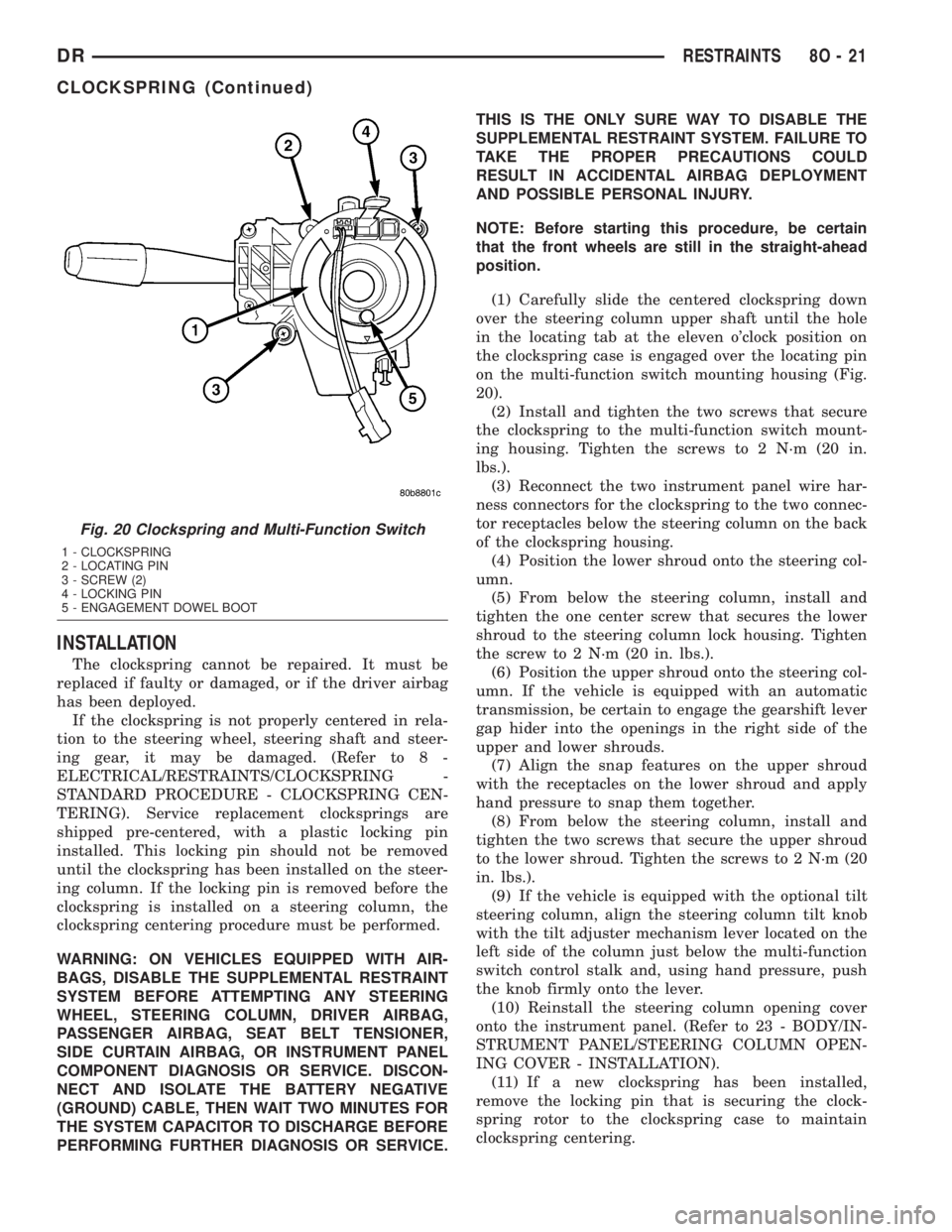
(1) Carefully slide the centered clockspring down
over the steering column upper shaft until the hole
in the locating tab at the eleven o'clock position on
the clockspring case is engaged over the locating pin
on the multi-function switch mounting housing (Fig.
20).
(2) Install and tighten the two screws that secure
the clockspring to the multi-function switch mount-
ing housing. Tighten the screws to 2 N´m (20 in.
lbs.).
(3) Reconnect the two instrument panel wire har-
ness connectors for the clockspring to the two connec-
tor receptacles below the steering column on the back
of the clockspring housing.
(4) Position the lower shroud onto the steering col-
umn.
(5) From below the steering column, install and
tighten the one center screw that secures the lower
shroud to the steering column lock housing. Tighten
the screw to 2 N´m (20 in. lbs.).
(6) Position the upper shroud onto the steering col-
umn. If the vehicle is equipped with an automatic
transmission, be certain to engage the gearshift lever
gap hider into the openings in the right side of the
upper and lower shrouds.
(7) Align the snap features on the upper shroud
with the receptacles on the lower shroud and apply
hand pressure to snap them together.
(8) From below the steering column, install and
tighten the two screws that secure the upper shroud
to the lower shroud. Tighten the screws to 2 N´m (20
in. lbs.).
(9) If the vehicle is equipped with the optional tilt
steering column, align the steering column tilt knob
with the tilt adjuster mechanism lever located on the
left side of the column just below the multi-function
switch control stalk and, using hand pressure, push
the knob firmly onto the lever.
(10) Reinstall the steering column opening cover
onto the instrument panel. (Refer to 23 - BODY/IN-
STRUMENT PANEL/STEERING COLUMN OPEN-
ING COVER - INSTALLATION).
(11) If a new clockspring has been installed,
remove the locking pin that is securing the clock-
spring rotor to the clockspring case to maintain
clockspring centering.
Fig. 20 Clockspring and Multi-Function Switch
1 - CLOCKSPRING
2 - LOCATING PIN
3 - SCREW (2)
4 - LOCKING PIN
5 - ENGAGEMENT DOWEL BOOT
DRRESTRAINTS 8O - 21
CLOCKSPRING (Continued)
Page 623 of 2895
NOTE: When reinstalling the steering wheel, be cer-
tain to index the yellow rubber booted engagement
dowel on the upper surface of the clockspring rotor
between the two fins cast into the lower surface of
the steering wheel armature hub.
(12) Reinstall the steering wheel onto the steering
column. (Refer to 19 - STEERING/COLUMN/STEER-
ING WHEEL - INSTALLATION).
(13) Reconnect the steering wheel wire harness
connectors to the upper clockspring connector recep-
tacles. Be certain that the steering wheel wire har-
ness is routed between the steering wheel back trim
cover and the steering wheel armature.
(14) Reinstall the driver airbag onto the steering
wheel. (Refer to 8 - ELECTRICAL/RESTRAINTS/
DRIVER AIRBAG - INSTALLATION).
DRIVER AIRBAG
DESCRIPTION
The color-keyed, injection molded, thermoplastic
driver airbag protective trim cover is the most visible
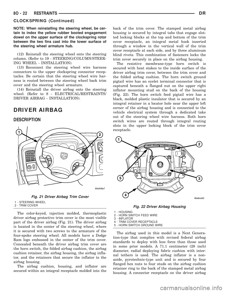
part of the driver airbag (Fig. 21). The driver airbag
is located in the center of the steering wheel, where
it is secured with two screws to the armature of the
four-spoke steering wheel. All models have a Dodge
Ram logo embossed in the center of the trim cover.
Concealed beneath the driver airbag trim cover are
the horn switch, the folded airbag cushion, the airbag
cushion retainer, the airbag housing, the airbag infla-
tor, and the retainers that secure the inflator to the
airbag housing.
The airbag cushion, housing, and inflator are
secured within an integral receptacle molded into theback of the trim cover. The stamped metal airbag
housing is secured by integral tabs that engage slot-
ted locking blocks at the top and bottom of the trim
cover receptacle, an integral metal hook inserted
through a window in the vertical wall of the trim
cover receptacle at each side, and by three aluminum
blind rivets. This combination of fasteners locks the
trim cover securely in place on the airbag housing.
The resistive membrane-type horn switch is
secured with heat stakes to the inside surface of the
driver airbag trim cover, between the trim cover and
the folded airbag cushion. The horn switch ground
pigtail wire has an eyelet terminal connector that is
captured beneath a flanged nut on the upper right
inflator mounting stud on the back of the housing
(Fig. 22). The horn switch feed pigtail wire has a
black, molded plastic insulator that is secured by an
integral retainer in a locator hole near the upper left
corner of the airbag housing and is connected to the
vehicle electrical system through a dedicated take
out of the steering wheel wire harness. Both horn
switch wires are routed through integral routing
slots in the upper locking block of the trim cover
receptacle.
The airbag used in this model is a Next Genera-
tion-type that complies with revised federal airbag
standards to deploy with less force than those used
in some prior models. A 71.1 centimeter (28 inch)
diameter, radial deploying fabric cushion with inter-
nal tethers is used. The airbag inflator is a non-
azide, pyrotechnic-type unit and is secured by four
flanged hex nuts to four studs on the airbag cushion
retainer ring to the back of the stamped metal airbag
housing. A connector receptacle on the driver airbag
Fig. 21 Driver Airbag Trim Cover
1 - STEERING WHEEL
2 - TRIM COVER
Fig. 22 Driver Airbag Housing
1 - HOUSING
2 - HORN SWITCH FEED WIRE
3 - INFLATOR
4 - TRIM COVER RECEPTACLE
5 - HORN SWITCH GROUND WIRE
8O - 22 RESTRAINTSDR
CLOCKSPRING (Continued)
Page 1628 of 2895
(8) The cylinder head cover gasket can be used
again. Install the gasket onto the head rail.For the
left side the number tab is at the front of
engine with the number up. For the right side
the number tab is at the rear of engine with the
number up.
CAUTION: The cylinder head cover fasteners have a
special plating. DO NOT use alternative fasteners.
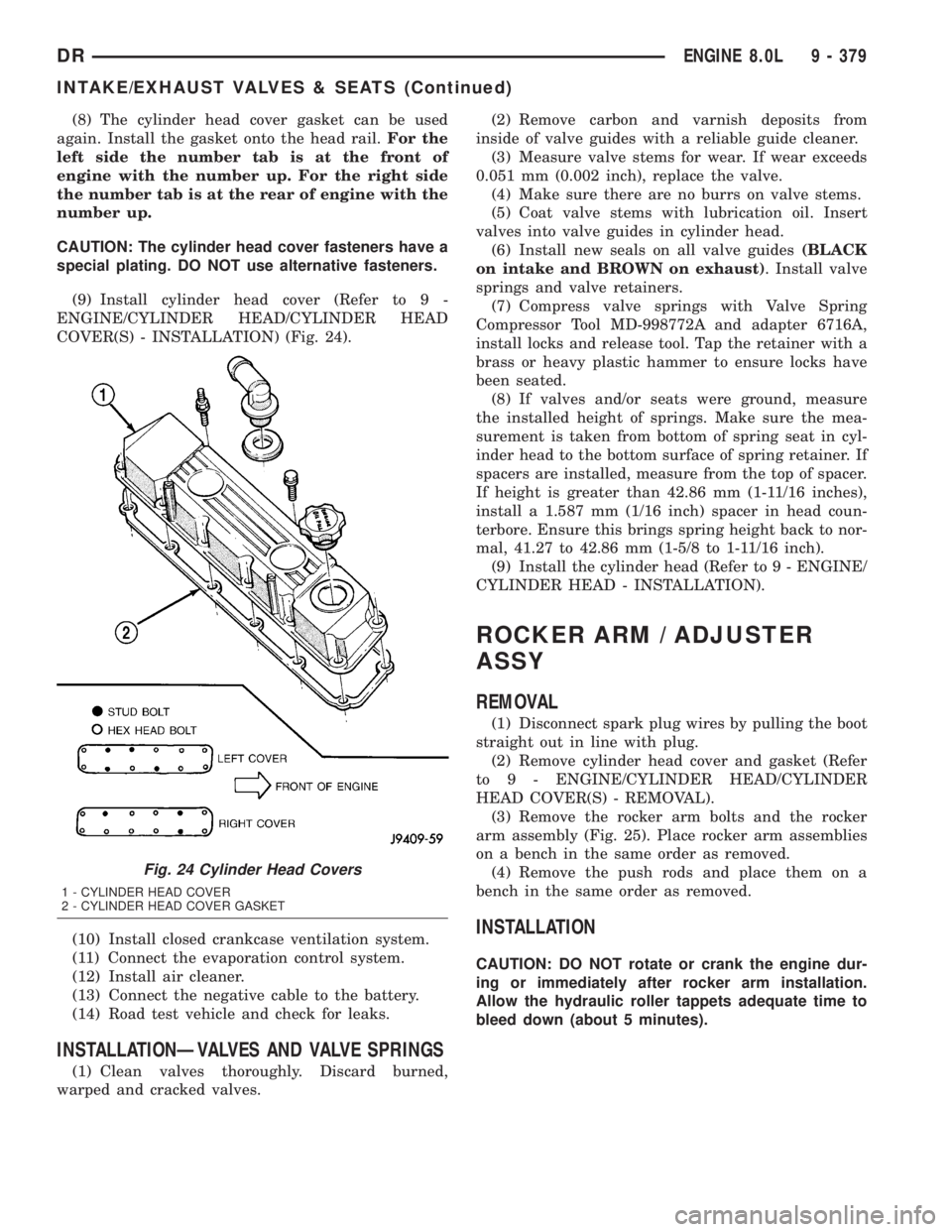
(9) Install cylinder head cover (Refer to 9 -
ENGINE/CYLINDER HEAD/CYLINDER HEAD
COVER(S) - INSTALLATION) (Fig. 24).
(10) Install closed crankcase ventilation system.
(11) Connect the evaporation control system.
(12) Install air cleaner.
(13) Connect the negative cable to the battery.
(14) Road test vehicle and check for leaks.
INSTALLATIONÐVALVES AND VALVE SPRINGS
(1) Clean valves thoroughly. Discard burned,
warped and cracked valves.(2) Remove carbon and varnish deposits from
inside of valve guides with a reliable guide cleaner.
(3) Measure valve stems for wear. If wear exceeds
0.051 mm (0.002 inch), replace the valve.
(4) Make sure there are no burrs on valve stems.
(5) Coat valve stems with lubrication oil. Insert
valves into valve guides in cylinder head.
(6) Install new seals on all valve guides(BLACK
on intake and BROWN on exhaust). Install valve
springs and valve retainers.
(7) Compress valve springs with Valve Spring
Compressor Tool MD-998772A and adapter 6716A,
install locks and release tool. Tap the retainer with a
brass or heavy plastic hammer to ensure locks have
been seated.
(8) If valves and/or seats were ground, measure
the installed height of springs. Make sure the mea-
surement is taken from bottom of spring seat in cyl-
inder head to the bottom surface of spring retainer. If
spacers are installed, measure from the top of spacer.
If height is greater than 42.86 mm (1-11/16 inches),
install a 1.587 mm (1/16 inch) spacer in head coun-
terbore. Ensure this brings spring height back to nor-
mal, 41.27 to 42.86 mm (1-5/8 to 1-11/16 inch).
(9) Install the cylinder head (Refer to 9 - ENGINE/
CYLINDER HEAD - INSTALLATION).
ROCKER ARM / ADJUSTER
ASSY
REMOVAL
(1) Disconnect spark plug wires by pulling the boot
straight out in line with plug.
(2) Remove cylinder head cover and gasket (Refer
to 9 - ENGINE/CYLINDER HEAD/CYLINDER
HEAD COVER(S) - REMOVAL).
(3) Remove the rocker arm bolts and the rocker
arm assembly (Fig. 25). Place rocker arm assemblies
on a bench in the same order as removed.
(4) Remove the push rods and place them on a
bench in the same order as removed.
INSTALLATION
CAUTION: DO NOT rotate or crank the engine dur-
ing or immediately after rocker arm installation.
Allow the hydraulic roller tappets adequate time to
bleed down (about 5 minutes).
Fig. 24 Cylinder Head Covers
1 - CYLINDER HEAD COVER
2 - CYLINDER HEAD COVER GASKET
DRENGINE 8.0L 9 - 379
INTAKE/EXHAUST VALVES & SEATS (Continued)
Page 1808 of 2895
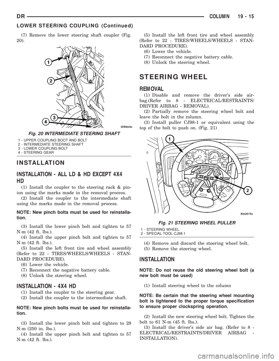
(7) Remove the lower steering shaft coupler (Fig.
20).
INSTALLATION
INSTALLATION - ALL LD & HD EXCEPT 4X4
HD
(1) Install the coupler to the steering rack & pin-
ion using the marks made in the removal process.
(2) Install the coupler to the intermediate shaft
using the marks made in the removal process.
NOTE: New pinch bolts must be used for reinstalla-
tion.
(3) Install the lower pinch bolt and tighten to 57
N´m (42 ft. lbs.).
(4) Install the upper pinch bolt and tighten to 57
N´m (42 ft. lbs.).
(5) Install the left front tire and wheel assembly
(Refer to 22 - TIRES/WHEELS/WHEELS - STAN-
DARD PROCEDURE).
(6) Lower the vehicle.
(7) Reconnect the negative battery cable.
(8) Unlock the steering wheel.
INSTALLATION - 4X4 HD
(1) Install the coupler to the steering gear.
(2) Install the coupler to the intermediate shaft.
NOTE: New pinch bolts must be used for reinstalla-
tion.
(3) Install the lower pinch bolt and tighten to 28
N´m (250 in. lbs.).
(4) Install the upper pinch bolt and tighten to 57
N´m (42 ft. lbs.).(5) Install the left front tire and wheel assembly
(Refer to 22 - TIRES/WHEELS/WHEELS - STAN-
DARD PROCEDURE).
(6) Lower the vehicle.
(7) Reconnect the negative battery cable.
(8) Unlock the steering wheel.
STEERING WHEEL
REMOVAL
(1) Disable and remove the driver's side air-
bag.(Refer to 8 - ELECTRICAL/RESTRAINTS/
DRIVER AIRBAG - REMOVAL).
(2) Partially remove the steering wheel bolt and
leave the bolt in the column.
(3) Install puller CJ98-1 or equivalent using the
top of the bolt to push on. (Fig. 21)
(4) Remove and discard the steering wheel bolt.
(5) Remove the steering wheel.
INSTALLATION
NOTE: Do not reuse the old steering wheel bolt (a
new bolt must be used)
(1) Install steering wheel to the column
NOTE: Be certain that the steering wheel mounting
bolt is tightened to the proper torque specification
to ensure proper clockspring operation.
(2) Install the new steering wheel bolt. Tighten the
bolt to 61 N´m (45 ft. lbs.).
(3) Install the driver's side air bag. (Refer to 8 -
ELECTRICAL/RESTRAINTS/DRIVER AIRBAG -
INSTALLATION).
Fig. 20 INTERMEDIATE STEERING SHAFT
1 - UPPER COUPLING BOOT AND BOLT
2 - INTERMEDIATE STEERING SHAFT
3 - LOWER COUPLING BOLT
4 - STEERING GEAR
Fig. 21 STEERING WHEEL PULLER
1 - STEERING WHEEL
2 - SPECIAL TOOL CJ98-1
DRCOLUMN 19 - 15
LOWER STEERING COUPLING (Continued)
Page 1824 of 2895
LINKAGE - INDEPENDENT FRONT SUSPENSION
TABLE OF CONTENTS
page page
LINKAGE - INDEPENDENT FRONT
SUSPENSION
DIAGNOSIS AND TESTING - OUTER TIE ROD
END ................................31TIE ROD END
REMOVAL - OUTER TIE ROD END..........31
INSTALLATION - OUTER TIE ROD END......32
LINKAGE - INDEPENDENT
FRONT SUSPENSION
DIAGNOSIS AND TESTING - OUTER TIE ROD
END
NOTE: If the outer tie rod end is equipped with a
lubrication fitting, grease the joint then road test
the vehicle before performing test.
(1) Raise the front of the vehicle. Place safety floor
stands under both lower control arms as far outboard
as possible. Lower the vehicle to allow the stands to
support some or all of the vehicle weight.
(2) Remove the front tires.
(3) Mount a dial indicator solidly to the vehicle
steering knuckle and then zero the dial indicator.
(4) Position indicator plunger on the topside of the
outer tie rod end.
NOTE: The dial indicator plunger must be perpen-
dicular to the machined surface of the outer tie rod
end.
(5) Position a pry bar in order to pry downwards
on the outer tie rod end.
(6) If the travel exceeds 0.5 mm (0.020 in.), replace
the outer tie rod end (Refer to 19 - STEERING/
LINKAGE/TIE ROD END - REMOVAL).
(7) If the outer tie rod end is within specs reinstall
the front tires (Refer to 22 - TIRES/WHEELS/
WHEELS - STANDARD PROCEDURE).
TIE ROD END
REMOVAL - OUTER TIE ROD END
NOTE: Do not twist the boot anytime during
removal or installation.
(1) Loosen the jam nut.
(2) Remove the outer tie rod end nut from the ball
stud.
(3) Separate the tie rod ball stud from the knuckle
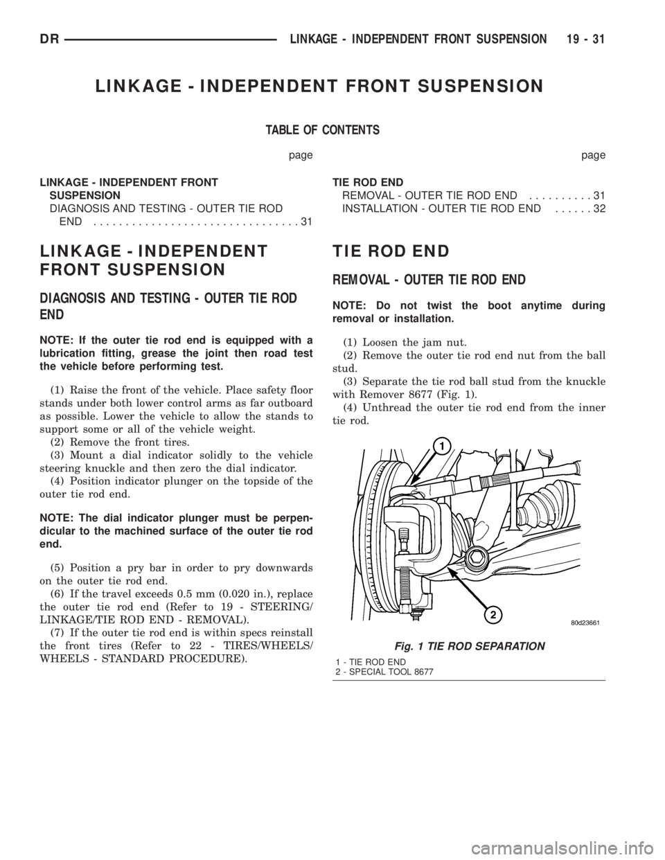
with Remover 8677 (Fig. 1).
(4) Unthread the outer tie rod end from the inner
tie rod.
Fig. 1 TIE ROD SEPARATION
1 - TIE ROD END
2 - SPECIAL TOOL 8677
DRLINKAGE - INDEPENDENT FRONT SUSPENSION 19 - 31
Page 1825 of 2895
INSTALLATION - OUTER TIE ROD END
NOTE: Do not twist the boot at anytime during
removal or installation.
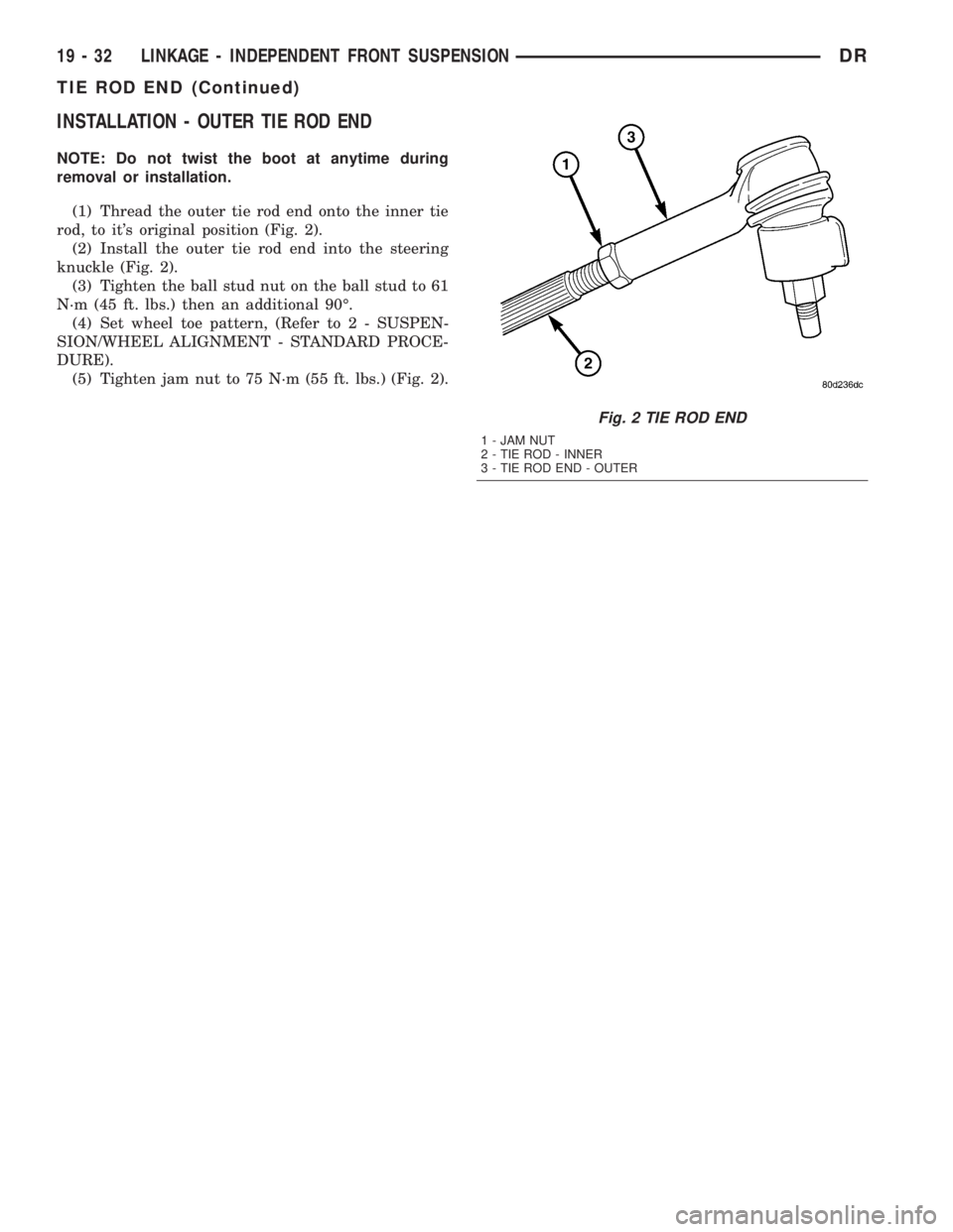
(1) Thread the outer tie rod end onto the inner tie
rod, to it's original position (Fig. 2).
(2) Install the outer tie rod end into the steering
knuckle (Fig. 2).
(3) Tighten the ball stud nut on the ball stud to 61
N´m (45 ft. lbs.) then an additional 90É.
(4) Set wheel toe pattern, (Refer to 2 - SUSPEN-
SION/WHEEL ALIGNMENT - STANDARD PROCE-
DURE).
(5) Tighten jam nut to 75 N´m (55 ft. lbs.) (Fig. 2).
Fig. 2 TIE ROD END
1 - JAM NUT
2 - TIE ROD - INNER
3 - TIE ROD END - OUTER
19 - 32 LINKAGE - INDEPENDENT FRONT SUSPENSIONDR
TIE ROD END (Continued)
Page 1842 of 2895
DIAGNOSIS AND TESTING
LOW LUBRICANT LEVEL
A low transmission lubricant level is generally the
result of a leak, inadequate lubricant fill or an incor-
rect lubricant level check. Leaks can occur at the
mating surfaces of the gear case, adaptor or exten-
sion housing, or from the front/rear seals. A sus-
pected leak could also be the result of an overfill
condition.
Leaks at the rear of the extension or adapter hous-
ing will be from the housing oil seals. Leaks at com-
ponent mating surfaces will probably be the result of
inadequate sealer, gaps in the sealer, incorrect bolt
tightening or use of a non-recommended sealer.
A leak at the front of the transmission will be from
either the front bearing retainer or retainer seal.
Lubricant may be seen dripping from the clutch
housing after extended operation. If the leak is
severe, it may also contaminate the clutch disc caus-
ing the disc to slip, grab and or chatter.
A correct lubricant level check can only be made
when the vehicle is level. Also allow the lubricant to
settle for a minute or so before checking. These rec-
ommendations will ensure an accurate check and
avoid an underfill or overfill condition. Always check
the lubricant level after any addition of fluid to avoid
an incorrect lubricant level condition.
HARD SHIFTING
Hard shifting is usually caused by a low lubricant
level, improper or contaminated lubricants. The con-
sequence of using non-recommended lubricants is
noise, excessive wear, internal bind and hard shift-
ing. Substantial lubricant leaks can result in gear,
shift rail, synchro, and bearing damage. If a leak
goes undetected for an extended period, the first indi-
cations of component damage are usually hard shift-
ing and noise.
Shift component damage or damaged clutch pres-
sure plate or disc are additional probable causes of
increased shift effort. Worn/damaged pressure plate
or disc can cause incorrect release. If clutch problem
is advanced, gear clash during shifts can result.
Worn or damaged synchro rings can cause gear clash
when shifting into any forward gear. In some new or
rebuilt transmissions, new synchro rings may tend to
stick slightly causing hard or noisy shifts. In most
cases this condition will decline as the rings wear-in.
TRANSMISSION NOISE
Most manual transmissions make some noise dur-
ing normal operation. Rotating gears generate a mild
whine that is audible, but generally only at extreme
speeds.Severe highly audible transmission noise is gener-
ally the initial indicator of a lubricant problem.
Insufficient, improper or contaminated lubricant will
promote rapid wear of gears, synchros, shift rails,
forks and bearings. The overheating caused by a
lubricant problem, can also lead to gear and bearing
damage.
REMOVAL
(1) Disconnect battery negative cable.
(2) Shift transmission into Neutral.
(3) Remove shift boot bezel screws and slide boot
upward on shift lever extension.
(4) Remove shift lever extension from the shift
tower and lever assembly.
(5) Raise vehicle on hoist.
(6) Remove skid plate, if equipped.
(7) Drain lubricant if transmission will be disas-
sembled for service.
(8) Mark propeller shaft/shafts and companion
flange yoke/yokes for installation reference and
remove propeller shaft/shafts.
(9) Disconnect harness from clips on transmission
housing.
(10) Remove transfer case linkage if equipped.
(11) Remove transfer case mounting nuts and
remove transfer case if equipped.
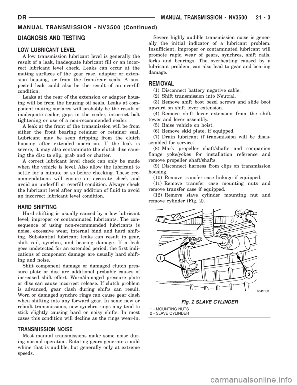
(12) Remove slave cylinder mounting nut and
remove cylinder (Fig. 2).
Fig. 2 SLAVE CYLINDER
1 - MOUNTING NUTS
2 - SLAVE CYLINDER
DRMANUAL TRANSMISSION - NV3500 21 - 3
MANUAL TRANSMISSION - NV3500 (Continued)
Page 1882 of 2895
The driver selects a particular gear by moving the
shift lever to the desired gear position. This move-
ment moves the internal transmission shift compo-
nents to begin the shift sequence. As the shift lever
moves the selected shift rail, the shift fork attached
to that rail begins to move. The fork is positioned in
a groove in the outer circumference of the synchro-
nizer sleeve. As the shift fork moves the synchronizer
sleeve, the synchronizer begins to speed-up or slow
down the selected gear (depending on whether the
driver is up-shifting or down-shifting). The synchro-
nizer does this by having the synchronizer hub
splined to the mainshaft, or the countershaft in some
cases, and moving the blocker ring into contact with
the gear's friction cone. As the blocker ring and fric-
tion cone come together, the gear speed is brought up
or down to the speed of the synchronizer. As the two
speeds match, the splines on the inside of the syn-
chronizer sleeve become aligned with the teeth on
the blocker ring and the friction cone and eventually
will slide over the teeth, locking the gear to the
mainshaft, or countershaft, through the synchronizer.
DIAGNOSIS AND TESTING
LOW LUBRICANT LEVEL
A low transmission lubricant level is generally the
result of a leak, inadequate lubricant fill or an incor-
rect lubricant level check. A correct lubricant level
check can only be made when the vehicle is level.
Also allow the lubricant to settle for a minute or so
before checking. These recommendations will ensure
an accurate check and avoid an underfill or overfill
condition. Always check the lubricant level after any
addition of fluid to avoid an incorrect lubricant level
condition.
Leaks can occur at the mating surfaces of the gear
case, adaptor or extension housing, or from the front/
rear seals. A suspected leak could also be the result
of an overfill condition. Leaks at the rear of the
extension or adapter housing will be from the hous-
ing oil seals. Leaks at component mating surfaces
will probably be the result of inadequate sealer, gaps
in the sealer, incorrect bolt tightening or use of a
non-recommended sealer. A leak at the front of the
transmission will be from either the front bearing
retainer or retainer seal. Lubricant may be seen drip-
ping from the clutch housing after extended opera-
tion. If the leak is severe, it may also contaminate
the clutch disc causing the disc to slip, grab and or
chatter.
HARD SHIFTING
Hard shifting is usually caused by a low lubricant
level, improper or contaminated lubricants. The con-
sequence of using non-recommended lubricants isnoise, excessive wear, internal bind and hard shift-
ing. Substantial lubricant leaks can result in gear,
shift rail, synchro, and bearing damage. If a leak
goes undetected for an extended period, the first indi-
cations of component damage are usually hard shift-
ing and noise.
Component damage, incorrect clutch adjustment or
damaged clutch pressure plate or disc are additional
probable causes of increased shift effort. Incorrect
adjustment or a worn/damaged pressure plate or disc
can cause incorrect release. If clutch problem is
advanced, gear clash during shifts can result. Worn
or damaged synchro rings can cause gear clash when
shifting into any forward gear. In some new or
rebuilt transmissions, new synchro rings may tend to
stick slightly causing hard or noisy shifts. In most
cases this condition will decline as the rings wear-in.
TRANSMISSION NOISE
Most manual transmissions make some noise dur-
ing normal operation. Rotating gears generate a mild
whine that is audible, but generally only at extreme
speeds. Severe highly audible transmission noise is
generally the initial indicator of a lubricant problem.
Insufficient, improper or contaminated lubricant
will promote rapid wear of gears, synchros, shift
rails, forks and bearings. The overheating caused by
a lubricant problem, can also lead to gear breakage.
REMOVAL
(1) Shift transmission into Neutral.
(2) Remove shift boot screws from floorpan and
slide boot upward on the shift lever.
(3) Remove shift lever extension from shift tower
and lever assembly.
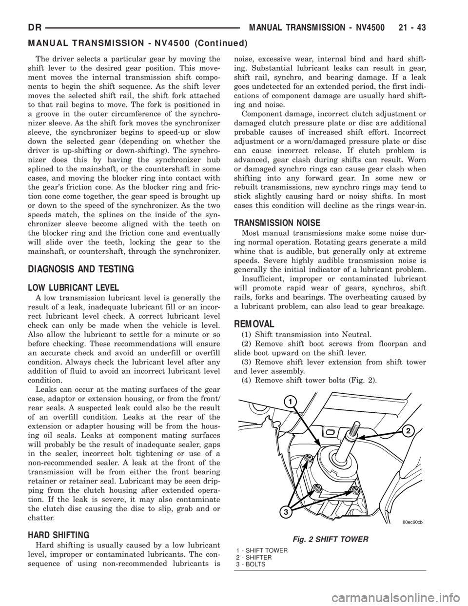
(4) Remove shift tower bolts (Fig. 2).
Fig. 2 SHIFT TOWER
1 - SHIFT TOWER
2 - SHIFTER
3 - BOLTS
DRMANUAL TRANSMISSION - NV4500 21 - 43
MANUAL TRANSMISSION - NV4500 (Continued)