2003 DODGE RAM boot
[x] Cancel search: bootPage 88 of 2895
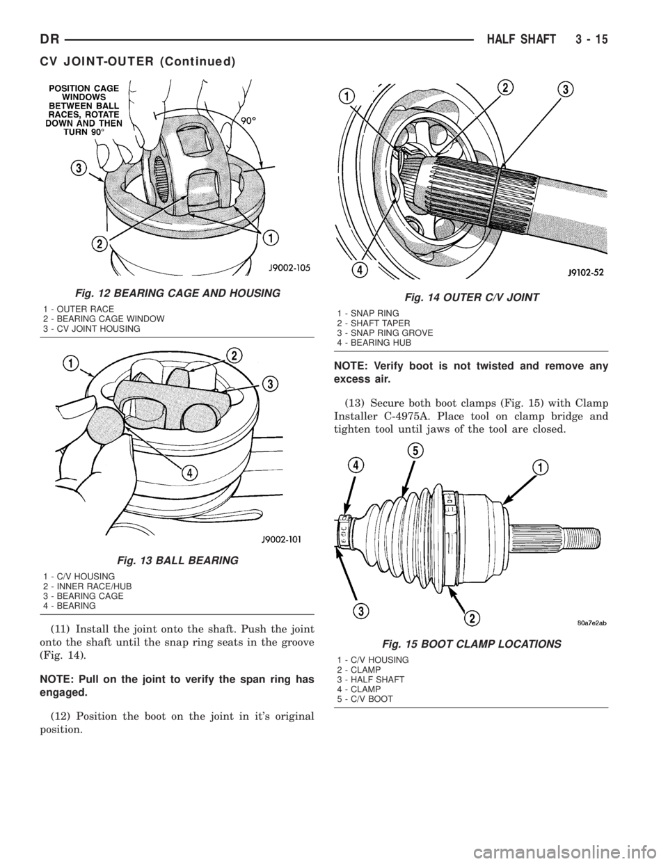
(11) Install the joint onto the shaft. Push the joint
onto the shaft until the snap ring seats in the groove
(Fig. 14).
NOTE: Pull on the joint to verify the span ring has
engaged.
(12) Position the boot on the joint in it's original
position.NOTE: Verify boot is not twisted and remove any
excess air.
(13) Secure both boot clamps (Fig. 15) with Clamp
Installer C-4975A. Place tool on clamp bridge and
tighten tool until jaws of the tool are closed.
Fig. 12 BEARING CAGE AND HOUSING
1 - OUTER RACE
2 - BEARING CAGE WINDOW
3 - CV JOINT HOUSING
Fig. 13 BALL BEARING
1 - C/V HOUSING
2 - INNER RACE/HUB
3 - BEARING CAGE
4 - BEARING
Fig. 14 OUTER C/V JOINT
1 - SNAP RING
2 - SHAFT TAPER
3 - SNAP RING GROVE
4 - BEARING HUB
Fig. 15 BOOT CLAMP LOCATIONS
1 - C/V HOUSING
2 - CLAMP
3 - HALF SHAFT
4 - CLAMP
5 - C/V BOOT
DRHALF SHAFT 3 - 15
CV JOINT-OUTER (Continued)
Page 89 of 2895
CV JOINT-INNER
REMOVAL
(1) Clamp shaft in a vise (with soft jaws) and sup-
port C/V joint.
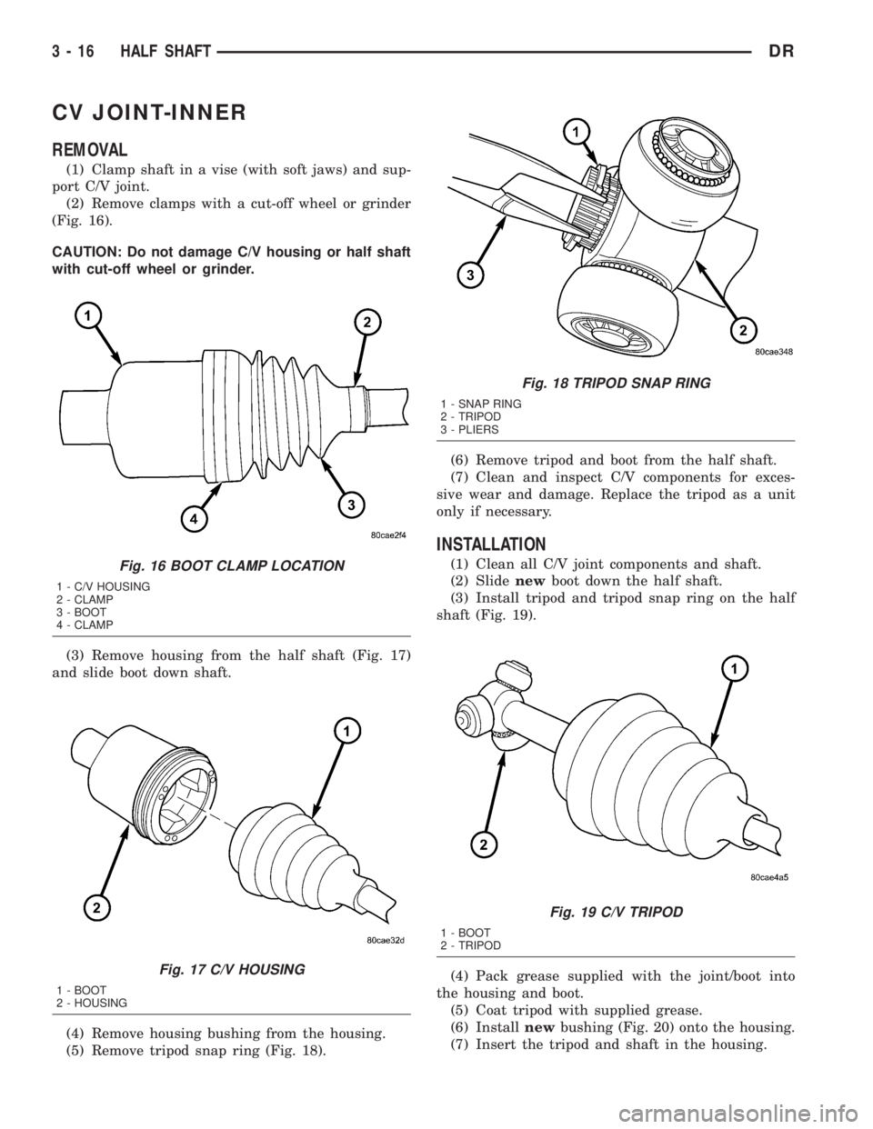
(2) Remove clamps with a cut-off wheel or grinder
(Fig. 16).
CAUTION: Do not damage C/V housing or half shaft
with cut-off wheel or grinder.
(3) Remove housing from the half shaft (Fig. 17)
and slide boot down shaft.
(4) Remove housing bushing from the housing.
(5) Remove tripod snap ring (Fig. 18).(6) Remove tripod and boot from the half shaft.
(7) Clean and inspect C/V components for exces-
sive wear and damage. Replace the tripod as a unit
only if necessary.
INSTALLATION
(1) Clean all C/V joint components and shaft.
(2) Slidenewboot down the half shaft.
(3) Install tripod and tripod snap ring on the half
shaft (Fig. 19).
(4) Pack grease supplied with the joint/boot into
the housing and boot.
(5) Coat tripod with supplied grease.
(6) Installnewbushing (Fig. 20) onto the housing.
(7) Insert the tripod and shaft in the housing.Fig. 16 BOOT CLAMP LOCATION
1 - C/V HOUSING
2 - CLAMP
3 - BOOT
4 - CLAMP
Fig. 17 C/V HOUSING
1 - BOOT
2 - HOUSING
Fig. 18 TRIPOD SNAP RING
1 - SNAP RING
2 - TRIPOD
3 - PLIERS
Fig. 19 C/V TRIPOD
1 - BOOT
2 - TRIPOD
3 - 16 HALF SHAFTDR
Page 90 of 2895
(8) Position the boot on the joint and shaft in it's
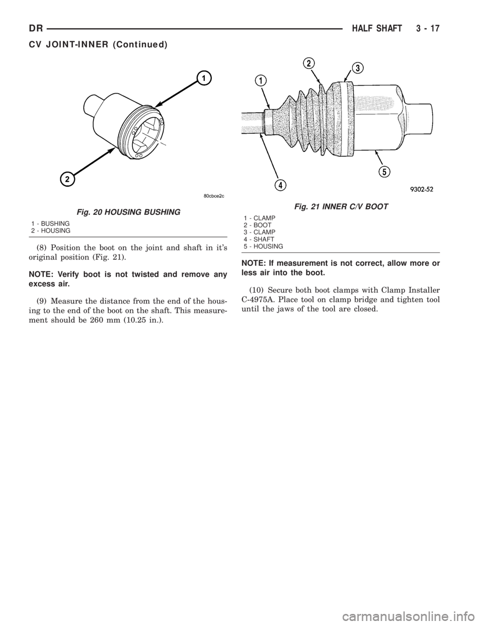
original position (Fig. 21).
NOTE: Verify boot is not twisted and remove any
excess air.
(9) Measure the distance from the end of the hous-
ing to the end of the boot on the shaft. This measure-
ment should be 260 mm (10.25 in.).NOTE: If measurement is not correct, allow more or
less air into the boot.
(10) Secure both boot clamps with Clamp Installer
C-4975A. Place tool on clamp bridge and tighten tool
until the jaws of the tool are closed.
Fig. 20 HOUSING BUSHING
1 - BUSHING
2 - HOUSING
Fig. 21 INNER C/V BOOT
1 - CLAMP
2 - BOOT
3 - CLAMP
4 - SHAFT
5 - HOUSING
DRHALF SHAFT 3 - 17
CV JOINT-INNER (Continued)
Page 232 of 2895
STANDARD PROCEDURE
STANDARD PROCEDURE - MANUAL BLEEDING
Use Mopar brake fluid, or an equivalent quality
fluid meeting SAE J1703-F and DOT 3 standards
only. Use fresh, clean fluid from a sealed container at
all times.
(1) Remove reservoir filler caps and fill reservoir.
(2) If calipers, or wheel cylinders were overhauled,
open all caliper and wheel cylinder bleed screws.
Then close each bleed screw as fluid starts to drip
from it. Top off master cylinder reservoir once more
before proceeding.
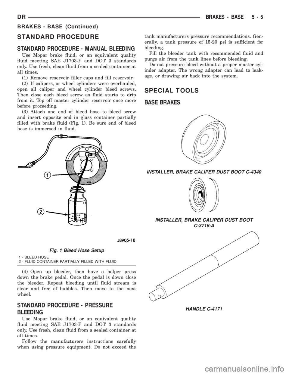
(3) Attach one end of bleed hose to bleed screw
and insert opposite end in glass container partially
filled with brake fluid (Fig. 1). Be sure end of bleed
hose is immersed in fluid.
(4) Open up bleeder, then have a helper press
down the brake pedal. Once the pedal is down close
the bleeder. Repeat bleeding until fluid stream is
clear and free of bubbles. Then move to the next
wheel.
STANDARD PROCEDURE - PRESSURE
BLEEDING
Use Mopar brake fluid, or an equivalent quality
fluid meeting SAE J1703-F and DOT 3 standards
only. Use fresh, clean fluid from a sealed container at
all times.
Follow the manufacturers instructions carefully
when using pressure equipment. Do not exceed thetank manufacturers pressure recommendations. Gen-
erally, a tank pressure of 15-20 psi is sufficient for
bleeding.
Fill the bleeder tank with recommended fluid and
purge air from the tank lines before bleeding.
Do not pressure bleed without a proper master cyl-
inder adapter. The wrong adapter can lead to leak-
age, or drawing air back into the system.
SPECIAL TOOLS
BASE BRAKES
Fig. 1 Bleed Hose Setup
1 - BLEED HOSE
2 - FLUID CONTAINER PARTIALLY FILLED WITH FLUID
INSTALLER, BRAKE CALIPER DUST BOOT C-4340
INSTALLER, BRAKE CALIPER DUST BOOT
C-3716-A
HANDLE C-4171
DRBRAKES - BASE 5 - 5
BRAKES - BASE (Continued)
Page 239 of 2895
OPERATION
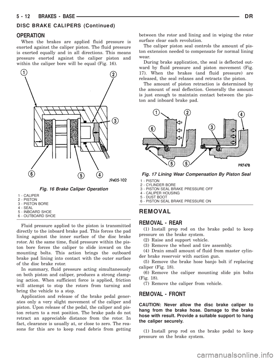
When the brakes are applied fluid pressure is
exerted against the caliper piston. The fluid pressure
is exerted equally and in all directions. This means
pressure exerted against the caliper piston and
within the caliper bore will be equal (Fig. 16).
Fluid pressure applied to the piston is transmitted
directly to the inboard brake pad. This forces the pad
lining against the inner surface of the disc brake
rotor. At the same time, fluid pressure within the pis-
ton bore forces the caliper to slide inward on the
mounting bolts. This action brings the outboard
brake pad lining into contact with the outer surface
of the disc brake rotor.
In summary, fluid pressure acting simultaneously
on both piston and caliper, produces a strong clamp-
ing action. When sufficient force is applied, friction
will attempt to stop the rotors from turning and
bring the vehicle to a stop.
Application and release of the brake pedal gener-
ates only a very slight movement of the caliper and
piston. Upon release of the pedal, the caliper and pis-
ton return to a rest position. The brake pads do not
retract an appreciable distance from the rotor. In
fact, clearance is usually at, or close to zero. The rea-
sons for this are to keep road debris from gettingbetween the rotor and lining and in wiping the rotor
surface clear each revolution.
The caliper piston seal controls the amount of pis-
ton extension needed to compensate for normal lining
wear.
During brake application, the seal is deflected out-
ward by fluid pressure and piston movement (Fig.
17). When the brakes (and fluid pressure) are
released, the seal relaxes and retracts the piston.
The amount of piston retraction is determined by
the amount of seal deflection. Generally the amount
is just enough to maintain contact between the pis-
ton and inboard brake pad.
REMOVAL
REMOVAL - REAR
(1) Install prop rod on the brake pedal to keep
pressure on the brake system.
(2) Raise and support vehicle.
(3) Remove the wheel and tire assembly.
(4) Drain small amount of fluid from master cylin-
der brake reservoir with suction gun.
(5) Remove the brake hose banjo bolt if replacing
caliper (Fig. 18).
(6) Remove the caliper mounting slide pin bolts
(Fig. 18).
(7) Remove the caliper from vehicle.
REMOVAL - FRONT
CAUTION: Never allow the disc brake caliper to
hang from the brake hose. Damage to the brake
hose with result. Provide a suitable support to hang
the caliper securely.
(1) Install prop rod on the brake pedal to keep
pressure on the brake system.
Fig. 16 Brake Caliper Operation
1 - CALIPER
2 - PISTON
3 - PISTON BORE
4 - SEAL
5 - INBOARD SHOE
6 - OUTBOARD SHOE
Fig. 17 Lining Wear Compensation By Piston Seal
1 - PISTON
2 - CYLINDER BORE
3 - PISTON SEAL BRAKE PRESSURE OFF
4 - CALIPER HOUSING
5 - DUST BOOT
6 - PISTON SEAL BRAKE PRESSURE ON
5 - 12 BRAKES - BASEDR
DISC BRAKE CALIPERS (Continued)
Page 241 of 2895
CAUTION: Do not blow the piston out of the bore
with sustained air pressure. This could result in a
cracked piston.
WARNING: NEVER ATTEMPT TO CATCH THE PIS-
TON AS IT LEAVES THE BORE. THIS COULD
RESULT IN PERSONAL INJURY.
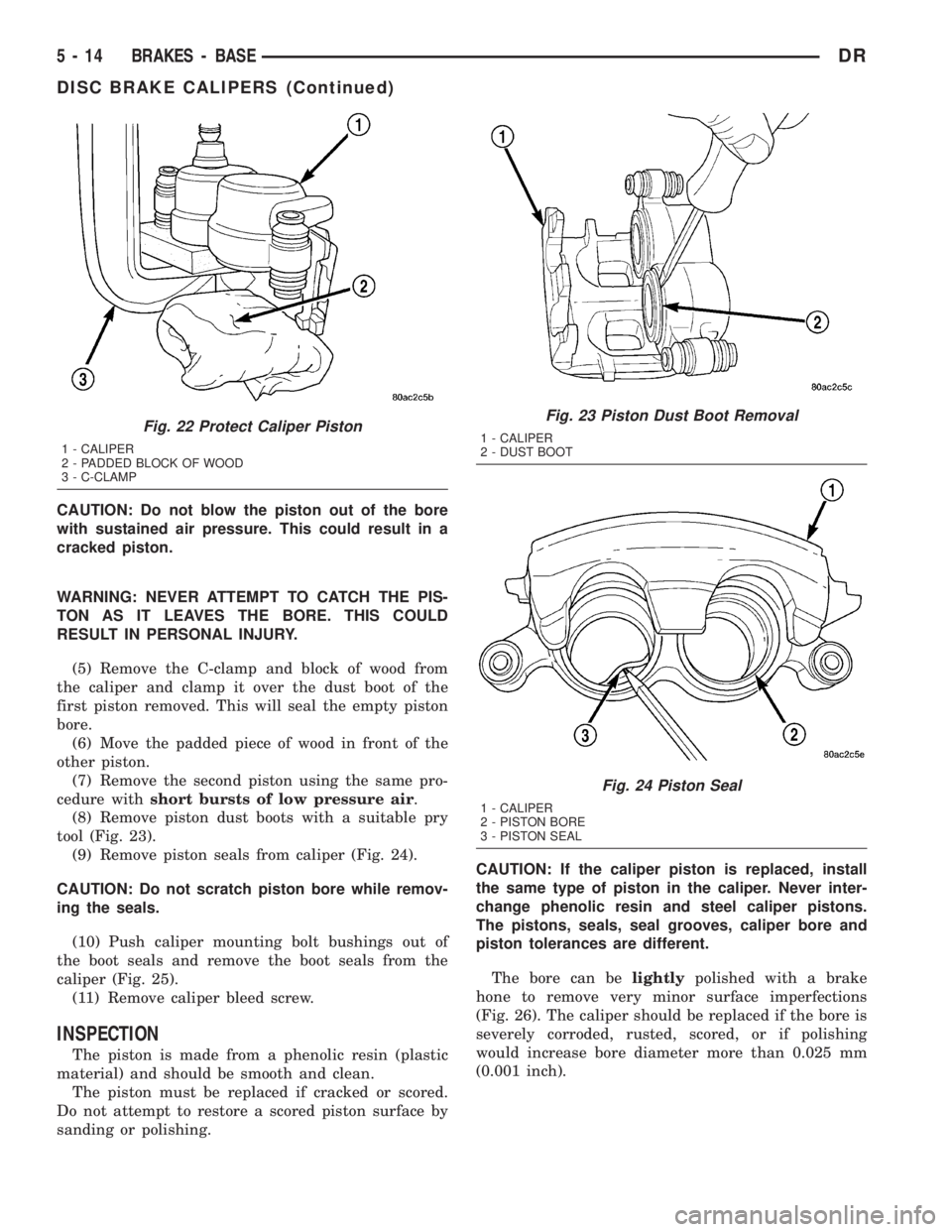
(5) Remove the C-clamp and block of wood from
the caliper and clamp it over the dust boot of the
first piston removed. This will seal the empty piston
bore.
(6) Move the padded piece of wood in front of the
other piston.
(7) Remove the second piston using the same pro-
cedure withshort bursts of low pressure air.
(8) Remove piston dust boots with a suitable pry
tool (Fig. 23).
(9) Remove piston seals from caliper (Fig. 24).
CAUTION: Do not scratch piston bore while remov-
ing the seals.
(10) Push caliper mounting bolt bushings out of
the boot seals and remove the boot seals from the
caliper (Fig. 25).
(11) Remove caliper bleed screw.
INSPECTION
The piston is made from a phenolic resin (plastic
material) and should be smooth and clean.
The piston must be replaced if cracked or scored.
Do not attempt to restore a scored piston surface by
sanding or polishing.CAUTION: If the caliper piston is replaced, install
the same type of piston in the caliper. Never inter-
change phenolic resin and steel caliper pistons.
The pistons, seals, seal grooves, caliper bore and
piston tolerances are different.
The bore can belightlypolished with a brake
hone to remove very minor surface imperfections
(Fig. 26). The caliper should be replaced if the bore is
severely corroded, rusted, scored, or if polishing
would increase bore diameter more than 0.025 mm
(0.001 inch).
Fig. 22 Protect Caliper Piston
1 - CALIPER
2 - PADDED BLOCK OF WOOD
3 - C-CLAMP
Fig. 23 Piston Dust Boot Removal
1 - CALIPER
2 - DUST BOOT
Fig. 24 Piston Seal
1 - CALIPER
2 - PISTON BORE
3 - PISTON SEAL
5 - 14 BRAKES - BASEDR
DISC BRAKE CALIPERS (Continued)
Page 242 of 2895
ASSEMBLY
CAUTION: Dirt, oil, and solvents can damage cali-
per seals. Insure assembly area is clean and dry.
(1) Lubricate caliper pistons, piston seals and pis-
ton bores with clean, fresh brake fluid.
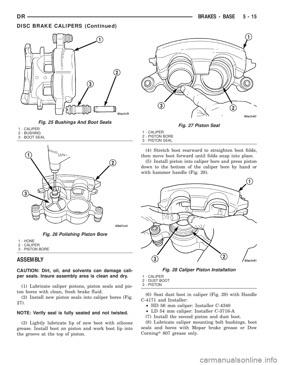
(2) Install new piston seals into caliper bores (Fig.
27).
NOTE: Verify seal is fully seated and not twisted.
(3) Lightly lubricate lip of new boot with silicone
grease. Install boot on piston and work boot lip into
the groove at the top of piston.(4) Stretch boot rearward to straighten boot folds,
then move boot forward until folds snap into place.
(5) Install piston into caliper bore and press piston
down to the bottom of the caliper bore by hand or
with hammer handle (Fig. 28).
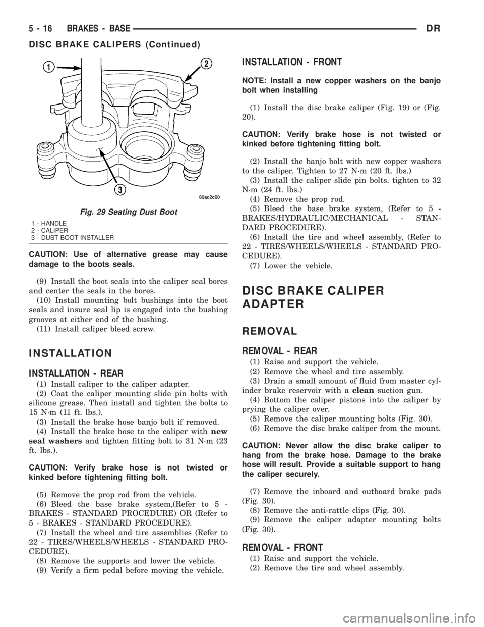
(6) Seat dust boot in caliper (Fig. 29) with Handle
C-4171 and Installer:
²HD 56 mm caliper: Installer C-4340
²LD 54 mm caliper: Installer C-3716-A
(7) Install the second piston and dust boot.
(8) Lubricate caliper mounting bolt bushings, boot
seals and bores with Mopar brake grease or Dow
Corningt807 grease only.
Fig. 25 Bushings And Boot Seals
1 - CALIPER
2 - BUSHING
3 - BOOT SEAL
Fig. 26 Polishing Piston Bore
1 - HONE
2 - CALIPER
3 - PISTON BORE
Fig. 27 Piston Seal
1 - CALIPER
2 - PISTON BORE
3 - PISTON SEAL
Fig. 28 Caliper Piston Installation
1 - CALIPER
2 - DUST BOOT
3 - PISTON
DRBRAKES - BASE 5 - 15
DISC BRAKE CALIPERS (Continued)
Page 243 of 2895
CAUTION: Use of alternative grease may cause
damage to the boots seals.
(9) Install the boot seals into the caliper seal bores
and center the seals in the bores.
(10) Install mounting bolt bushings into the boot
seals and insure seal lip is engaged into the bushing
grooves at either end of the bushing.
(11) Install caliper bleed screw.
INSTALLATION
INSTALLATION - REAR
(1) Install caliper to the caliper adapter.
(2) Coat the caliper mounting slide pin bolts with
silicone grease. Then install and tighten the bolts to
15 N´m (11 ft. lbs.).
(3) Install the brake hose banjo bolt if removed.
(4) Install the brake hose to the caliper withnew
seal washersand tighten fitting bolt to 31 N´m (23
ft. lbs.).
CAUTION: Verify brake hose is not twisted or
kinked before tightening fitting bolt.
(5) Remove the prop rod from the vehicle.
(6) Bleed the base brake system,(Refer to 5 -
BRAKES - STANDARD PROCEDURE) OR (Refer to
5 - BRAKES - STANDARD PROCEDURE).
(7) Install the wheel and tire assemblies (Refer to
22 - TIRES/WHEELS/WHEELS - STANDARD PRO-
CEDURE).
(8) Remove the supports and lower the vehicle.
(9) Verify a firm pedal before moving the vehicle.
INSTALLATION - FRONT
NOTE: Install a new copper washers on the banjo
bolt when installing
(1) Install the disc brake caliper (Fig. 19) or (Fig.
20).
CAUTION: Verify brake hose is not twisted or
kinked before tightening fitting bolt.
(2) Install the banjo bolt with new copper washers
to the caliper. Tighten to 27 N´m (20 ft. lbs.)
(3) Install the caliper slide pin bolts. tighten to 32
N´m (24 ft. lbs.)
(4) Remove the prop rod.
(5) Bleed the base brake system, (Refer to 5 -
BRAKES/HYDRAULIC/MECHANICAL - STAN-
DARD PROCEDURE).
(6) Install the tire and wheel assembly, (Refer to
22 - TIRES/WHEELS/WHEELS - STANDARD PRO-
CEDURE).
(7) Lower the vehicle.
DISC BRAKE CALIPER
ADAPTER
REMOVAL
REMOVAL - REAR
(1) Raise and support the vehicle.
(2) Remove the wheel and tire assembly.
(3) Drain a small amount of fluid from master cyl-
inder brake reservoir with acleansuction gun.
(4) Bottom the caliper pistons into the caliper by
prying the caliper over.
(5) Remove the caliper mounting bolts (Fig. 30).
(6) Remove the disc brake caliper from the mount.
CAUTION: Never allow the disc brake caliper to
hang from the brake hose. Damage to the brake
hose will result. Provide a suitable support to hang
the caliper securely.
(7) Remove the inboard and outboard brake pads
(Fig. 30).
(8) Remove the anti-rattle clips (Fig. 30).
(9) Remove the caliper adapter mounting bolts
(Fig. 30).
REMOVAL - FRONT
(1) Raise and support the vehicle.
(2) Remove the tire and wheel assembly.
Fig. 29 Seating Dust Boot
1 - HANDLE
2 - CALIPER
3 - DUST BOOT INSTALLER
5 - 16 BRAKES - BASEDR
DISC BRAKE CALIPERS (Continued)