2003 DODGE RAM Ignition switch diagram
[x] Cancel search: Ignition switch diagramPage 589 of 2895

POWER MIRROR MOTOR TEST
If the power mirror switch is receiving proper cur-
rent and ground and mirrors do not operate, proceed
with power mirror motor test. Refer to the appropri-
ate wiring information. The wiring information
includes wiring diagrams, proper wire and connector
repair procedures, details of wire harness routing
and retention, connector pin-out information and
location views for the various wire harness connec-
tors, splices and grounds.
(1) Remove the power mirror switch (Refer to 8 -
ELECTRICAL/POWER LOCKS/DOOR MODULE -
REMOVAL).
(2) Disconnect wire harness connector to power
mirror switch (Fig. 1).
(3) Using two jumper wires:
²Connect one to a 12 volt source
²Connect the other to a good body ground
²Refer to the Mirror Motor Test Chart for proper
wire connections at the switch connector
MIRROR MOTOR TEST CHART
12 VOLTS GROUND MIRROR REACTION
SWITCH CONNECTOR RIGHT LEFT
PIN 1 PIN 2 - UP
PIN 6 PIN 2 - LEFT
PIN 2 PIN 1 - DOWN
PIN 2 PIN 6 - RIGHT
PIN 7 PIN 2 UP -
PIN 4 PIN 2 LEFT -
PIN 2 PIN 7 DOWN -
PIN 2 PIN 4 RIGHT -
(4) If results shown in table are not obtained,
check for open or shorted circuit. Replace mirror
assembly as necessary.
AUTOMATIC DAY / NIGHT
MIRROR
DESCRIPTION
The automatic day/night mirror uses a thin layer
of electrochromic material between two pieces of con-
ductive glass to make up the face of the mirror.
When the mirror switch is in the On position, two
photocell sensors are used by the mirror circuitry to
monitor external light levels and adjust the reflec-
tance of the mirror.
OPERATION
The ambient photocell sensor is located on the for-
ward-facing (windshield side) of the rear view mirror
housing, and detects the ambient light levels outside
of the vehicle. The headlamp photocell sensor is
located inside the rear view mirror housing behind
the mirror glass and faces rearward, to detect the
level of the light being received at the rear window
side of the mirror. When the circuitry of the auto-
matic day/night mirror detects that the difference
between the two light levels is too great (the light
level received at the rear of the mirror is much
higher than that at the front of the mirror), it begins
to darken the mirror.
The automatic day/night mirror circuitry also mon-
itors the transmission using an input from the
backup lamp circuit. The mirror circuitry is pro-
grammed to automatically disable its self-dimming
feature whenever it senses that the transmission
backup lamp circuit is energized.
The automatic day/night mirror is a completely
self-contained unit and cannot be repaired. If faulty
or damaged, the entire mirror assembly must be
replaced.
DIAGNOSIS AND TESTING - AUTOMATIC DAY /
NIGHT MIRROR
For complete circuit diagrams, refer to the appro-
priate wiring information. The wiring information
includes wiring diagrams, proper wire and connector
repair procedures, details of wire harness routing
and retention, connector pin-out information and
location views for the various wire harness connec-
tors, splices and grounds.
(1) Check the fuse in the Integrated Power Module
(IPM). If OK, go to Step 2. If not OK, repair the
shorted circuit or component as required and replace
the faulty fuse.
(2) Turn the ignition switch to the On position.
Check for battery voltage at the fuse in the IPM. If
OK, go to Step 3. If not OK, repair the open circuit to
the ignition switch as required.
Fig. 1 POWER MIRROR SWITCH CONNECTOR
8N - 12 POWER MIRRORSDR
POWER MIRRORS (Continued)
Page 591 of 2895
POWER SEATS
TABLE OF CONTENTS
page page
POWER SEATS
DESCRIPTION.........................14
OPERATION...........................14
DIAGNOSIS AND TESTING - POWER SEAT
SYSTEM............................14
DRIVER SEAT SWITCH
DESCRIPTION.........................15
OPERATION...........................15
DIAGNOSIS AND TESTING - DRIVER SEAT
SWITCH............................15
REMOVAL.............................16
INSTALLATION.........................16
PASSENGER SEAT SWITCH
DESCRIPTION.........................16
OPERATION...........................17
DIAGNOSIS AND TESTING - PASSENGER
SEAT SWITCH........................17REMOVAL.............................17
INSTALLATION.........................18
POWER SEAT TRACK
DESCRIPTION.........................18
OPERATION...........................18
DIAGNOSIS AND TESTING - POWER SEAT
TRACK.............................18
REMOVAL.............................19
INSTALLATION.........................19
LUMBAR CONTROL SWITCH
DESCRIPTION.........................19
OPERATION...........................19
REMOVAL.............................19
LUMBAR MOTOR
DESCRIPTION.........................19
OPERATION...........................20
DIAGNOSIS AND TESTING - LUMBAR MOTOR..20
POWER SEATS
DESCRIPTION
The power seat system option allows the driver or
passenger to electrically adjust the seat position for
optimum control and comfort using the power seat
switches located on the outboard seat cushion side
shield. The power seat system allows the seating
position to be adjusted forward, rearward, front up,
front down, rear up, or rear down. The power seat
system receives battery current through a fuse in the
Integrated Power Module, regardless of the ignition
switch position. The power seat system includes the
following components:
²Driver Power Seat Switch
²Passenger Power Seat Switch
²Driver Power Seat Track
²Passenger Power Seat Track
²Power Lumbar Adjuster(s)
Some models equipped with the power seat option
also feature a power operated lumbar support in the
seat back. The power lumbar support allows the user
to inflate or deflate a bladder located in the lower
seat back to achieve optimum comfort and support in
the lower lumbar region of the spinal column. The
power lumbar support shares the battery feed circuit
of the power seat system.
Following are general descriptions of the major
components in the power seat system. Refer to
Heated Seat Systemfor information on the individ-ually controlled heated front seats. Refer to the own-
er's manual in the vehicle glove box for more
information on the features, use and operation of the
power seat system.
OPERATION
The power seat system allows the driver and/or
front passenger seating positions to be adjusted elec-
trically and independently using the separate power
seat switches found on the outboard seat cushion
side shield of each front seat. See the owner's manual
in the vehicle glove box for more information on the
features, use and operation of the power seat system.
DIAGNOSIS AND TESTING - POWER SEAT
SYSTEM
Before any testing of the power seat system is
attempted, the battery should be fully-charged and
all wire harness connections and pins checked to
ensure proper continuity and grounds. For circuit
descriptions and diagrams, refer to Wiring Diagrams.
With the dome lamp on, apply the power seat
switch in the direction of the failure. If the dome
lamp dims, the seat may be jamming. Check under
and behind the seat for binding or obstructions. If
the dome lamp does not dim, proceed with testing of
the individual components and circuits.
8N - 14 POWER SEATSDR
Page 598 of 2895
POWER WINDOWS
TABLE OF CONTENTS
page page
POWER WINDOWS
DESCRIPTION.........................21
OPERATION...........................21
DIAGNOSIS AND TESTING - POWER
WINDOWS...........................21
WINDOW MOTOR
REMOVAL.............................22WINDOW SWITCH
DIAGNOSIS AND TESTING - WINDOW
SWITCH............................22
REMOVAL.............................23
INSTALLATION.........................23
POWER WINDOWS
DESCRIPTION
The power window system allows each of the door
windows to be raised and lowered electrically by
actuating a switch on each door panel. A master
switch on the drivers door allows the driver to raise
or lower each of the passenger door windows and to
lock out the individual switches on the passenger
doors from operation. The power window system
receives battery feed through a fuse in the Integrated
Power Module (IPM) and a circuit breaker located in
the instrument panel wiring harness near the park
brake pedal, only when the ignition switch is in the
RUN or ACCESSORY position.
OPERATION
WINDOW SWITCH
The power window switches control the battery
and ground feeds to the power window motors. The
passenger door power window switches receive their
battery and ground feeds through the circuitry of the
drivers window switch. When the power window lock-
out switch is in the Lock position, the battery feed
for the passenger door window switches is inter-
rupted.
WINDOW MOTOR
Window motors use permanent type magnets. The
B+ and ground applied at the motor terminal pins
will cause the motor to rotate in one direction.
Reversing current through the motor terminals will
cause the motor to rotate in the opposite direction.
Refer to the appropriate wiring information. The
wiring information includes wiring diagrams, proper
wire and connector repair procedures, details of wire
harness routing and retention, connector pin-out
information and location views for the various wire
harness connectors, splices and grounds.
DIAGNOSIS AND TESTING - POWER
WINDOWS
WIRING VOLTAGE TEST
The following wiring test determines whether or
not voltage is continuous through the body harness
to the front switch.
(1) Remove the Driver Door Module (Refer to 8 -
ELECTRICAL/POWER LOCKS/DOOR MODULE -
REMOVAL).
(2) Disconnect wire connector from back of power
window switch.
(3) Switch ignition to the ON position.
(4) Connect the clip end of a 12 volt test light to
Pin 14 of the window switch harness connector.
Touch the test light probe to Pin 10.
²If the test light illuminates, the wiring circuit
between the battery and switch is OK.
²If the lamp does not illuminate, first check the
fuse in the Integrated Power Module (IPM). Check
the circuit breaker located near the park brake
pedal. If fuse and circuit breaker are OK, then check
for a broken wire.
Refer to the appropriate wiring information. The
wiring information includes wiring diagrams, proper
wire and connector repair procedures, details of wire
harness routing and retention, connector pin-out
information and location views for the various wire
harness connectors, splices and grounds.
POWER WINDOW MOTOR TEST
If the power window motor is receiving proper cur-
rent and ground and does not operate, proceed with
motor test. Refer to the appropriate wiring informa-
tion. The wiring information includes wiring dia-
grams, proper wire and connector repair procedures,
details of wire harness routing and retention, connec-
tor pin-out information and location views for the
various wire harness connectors, splices and grounds.
(1) Remove front door trim panel as necessary to
gain access to power window motor wire connector
DRPOWER WINDOWS 8N - 21
Page 599 of 2895

(Refer to 23 - BODY/DOOR - FRONT/TRIM PANEL -
REMOVAL).
(2) Disconnect power window motor wire connector
from door harness.
(3) Using two jumper wires, connect one to a bat-
tery (+) source and the other to a good ground (-).
(4) Connect the Negative (-) jumper probe to one of
the motor connector terminals.
(5) Momentarily touch the Positive (+) jumper
probe to the other motor connector terminal.
When positive probe is connected the motor should
rotate in one direction to either move window up or
down. If window is all the way up or down the motor
will grunt and the inner door panel will flex when
actuated in that one direction.
(6) Reverse jumper probes at the motor connector
terminals and window should now move in opposite
direction. If window does not move or grunt, replace
the motor.
If window moved completely up or down, reverse
the jumper probes and cycle window to the opposite
position to verify full operation.
If motor grunts and does not move, verify that reg-
ulator is not binding.
WINDOW MOTOR
REMOVAL
The window motor is serviced with the window reg-
ulator (Refer to 23 - BODY/DOOR - FRONT/WINDOW
REGULATOR - REMOVAL) or (Refer to 23 - BODY/
DOORS - REAR/WINDOW REGULATOR - REMOVAL).
WINDOW SWITCH
DIAGNOSIS AND TESTING - WINDOW SWITCH
The Light-Emitting Diode (LED) illumination
lamps for all of the power window and lock switch
and bezel unit switch paddles receive battery current
through the power window circuit breaker in the
junction block. If all of the LEDs are inoperative in
both the power window and lock switch units and the
power windows are inoperative, (Refer to 8 - ELEC-
TRICAL/POWER WINDOWS - DIAGNOSIS AND
TESTING). If the power windows operate, but any or
all of the LEDs are inoperative, the power window
and lock switch units with the inoperative LED(s) is
faulty and must be replaced. For complete circuit dia-
grams, refer to the appropriate wiring information.
The wiring information includes wiring diagrams,
proper wire and connector repair procedures, details
of wire harness routing and retention, connector pin-
out information and location views for the various
wire harness connectors, splices and grounds.(1) Check the fuse in the Integrated Power Module
(IPM) and the circuit breaker located near the park
brake pedal. If OK, go to Step 2. If not OK, replace
the faulty fuse or circuit breaker.
(2) Turn the ignition switch to the On position.
Check for battery voltage at the fuse in the Inte-
grated Power Module (IPM). If OK, turn the ignition
switch to the Off position and go to Step 3. If not OK,
check circuit breaker and repair the circuit to the
ignition switch as required.
(3) Disconnect and isolate the battery negative
cable. Remove the power window switch unit from
the door trim panel (passenger doors). The drivers
door switch is included with the Driver Door Module
(Refer to 8 - ELECTRICAL/POWER LOCKS/DOOR
MODULE - DIAGNOSIS AND TESTING) for service
procedures. Unplug the wire harness connector from
the switch unit.
(4) Test the power window switch continuity. See
the Power Window Switch Continuity charts to deter-
mine if the continuity is correct in the Off, Up and
Down switch positions (Fig. 1). If OK, (Refer to 8 -
ELECTRICAL/POWER WINDOWS - DIAGNOSIS
AND TESTING). If not OK, replace the faulty switch.
POWER WINDOW SWITCH CONTINUITY
CHART
SWITCH POSITION CONTINUITY BETWEEN
NEUTRAL PIN 2 AND 5, PIN 4 AND 1
UP (FRONT
PASSENGER)PIN 6 AND 5
UP (REAR
PASSENGER)PIN 6 AND 1
DOWN (FRONT
PASSENGER)PIN 6 AND 1
DOWN (REAR
PASSENGER)PIN 6 AND 5
Fig. 1 PASSENGER DOOR SWITCH
8N - 22 POWER WINDOWSDR
POWER WINDOWS (Continued)
Page 650 of 2895
outboard seat belt and retractor unit must be
replaced. (Refer to 8 - ELECTRICAL/RESTRAINTS/
FRONT OUTBOARD SEAT BELT & RETRACTOR -
REMOVAL).
OPERATION
The seat belt tension reducer is controlled by a
ground signal received from the seat belt switch on
the seat belt switch sense circuit and a battery cur-
rent signal received from the ignition switch on the
fused ignition switch output (run-accessory) circuit.
When the seat belt switch is closed (the driver side
front seat belt is fastened) and the ignition switch is
in the On or Accessory positions, the seat belt tension
reducer solenoid is energized. When the solenoid is
energized, it actuates a mechanism within the driver
side front outboard seat belt retractor to reduce the
normal recoil spring tension exerted by the retractor
spool, which is designed to reel in the seat belt web-
bing onto the spool. When the driver side seat belt is
unbuckled or if the ignition switch is turned to any
position except On or Accessory, the tension reducer
solenoid is de-energized and the normal recoil spring
tension of the retractor is restored.
The action of the seat belt tension reducer results
in improved seat belt comfort for the driver. Reducing
the seat belt retractor recoil spring tension is desir-
able on standard cab models of this vehicle and not
on the quad cab model due to the different mounting
position required for the seat belt turning loop on the
B-pillar relative to the driver's seat position on the
standard cab model. The seat belt tension reducer
may be diagnosed using conventional diagnostic tools
and methods.
DIAGNOSIS AND TESTING - SEAT BELT
TENSION REDUCER
Refer to the appropriate wiring information. The
wiring information includes wiring diagrams, proper
wire and connector repair procedures, details of wire
harness routing and retention, connector pin-out
information and location views for the various wire
harness connectors, splices and grounds.
WARNING: ON VEHICLES EQUIPPED WITH AIR-
BAGS, DISABLE THE SUPPLEMENTAL RESTRAINTSYSTEM BEFORE ATTEMPTING ANY STEERING
WHEEL, STEERING COLUMN, DRIVER AIRBAG,
PASSENGER AIRBAG, SEAT BELT TENSIONER,
SIDE CURTAIN AIRBAG, OR INSTRUMENT PANEL
COMPONENT DIAGNOSIS OR SERVICE. DISCON-
NECT AND ISOLATE THE BATTERY NEGATIVE
(GROUND) CABLE, THEN WAIT TWO MINUTES FOR
THE SYSTEM CAPACITOR TO DISCHARGE BEFORE
PERFORMING FURTHER DIAGNOSIS OR SERVICE.
THIS IS THE ONLY SURE WAY TO DISABLE THE
SUPPLEMENTAL RESTRAINT SYSTEM. FAILURE TO
TAKE THE PROPER PRECAUTIONS COULD
RESULT IN ACCIDENTAL AIRBAG DEPLOYMENT
AND POSSIBLE PERSONAL INJURY.
(1) Disconnect and isolate the battery negative
cable. Disconnect the body wire harness connector for
the seat belt tension reducer from the tension
reducer connector receptacle on the driver side front
outboard seat belt and retractor unit. Using an ohm-
meter, measure the resistance between the seat belt
switch sense circuit terminal pin and the fused igni-
tion switch output (run-accessory) circuit terminal
pin in the tension reducer connector receptacle on
the retractor. Resistance through the tension reducer
solenoid coil should be 53 ohms at 20É C (68É F). If
OK, go to Step 2. If not OK, replace the faulty driver
side front outboard seat belt and retractor unit.
(2) Check for continuity between the seat belt
switch sense circuit cavity of the body wire harness
connector for the seat belt tension reducer and a good
ground. There should be continuity with the driver
side front seat belt buckled, and no continuity with
the driver side front seat belt unbuckled. If OK, go to
Step 3. If not OK, repair the shorted or open seat
belt switch sense circuit between the tension reducer
and the seat belt switch as required.
(3) Reconnect the battery negative cable. Check for
battery current at the fused ignition switch output
(run-accessory) circuit of the body wire harness con-
nector for the seat belt tension reducer. There should
be battery current with the ignition switch in the On
or Accessory positions, and no battery current with
the ignition switch in any other position. If not OK,
repair the shorted or open fused ignition switch out-
put (run-accessory) circuit between the tension
reducer and the ignition switch as required.
DRRESTRAINTS 8O - 49
SEAT BELT TENSION REDUCER (Continued)
Page 672 of 2895
placed in its ªCustomer Learnº programming mode.
See Sentry Key Immobilizer System Transponder
Programming in this section for more information on
the ªCustomer Learnº programming mode.
For diagnosis or initialization of the SKIM and the
PCM, a DRBIIItscan tool and the proper Powertrain
Diagnostic Procedures manual are required. The
SKIM cannot be repaired and, if faulty or damaged,
the unit must be replaced.
DIAGNOSIS AND TESTING
VEHICLE THEFT SECURITY SYSTEM
WARNING: ON VEHICLES EQUIPPED WITH AIR-
BAGS, REFER TO RESTRAINT SYSTEMS BEFORE
ATTEMPTING ANY STEERING WHEEL, STEERING
COLUMN, OR INSTRUMENT PANEL COMPONENT
DIAGNOSIS OR SERVICE. FAILURE TO TAKE THE
PROPER PRECAUTIONS COULD RESULT IN ACCI-
DENTAL AIRBAG DEPLOYMENT AND POSSIBLE
PERSONAL INJURY.
NOTE: The most reliable, efficient, and accurate
means to diagnose the Vehicle Theft Security Sys-
tem (VTSS) and Sentry Key Immobilizer System
(SKIS) involves the use of a DRBlllTscan tool and
the proper Powertrain Diagnostic Procedures man-
ual.
The Vehicle Theft Security System (VTSS), Sentry
Key Immobilizer System (SKIS) and the Programma-
ble Communication Interface (PCI) bus network
should be diagnosed using a DRBIIItscan tool. The
DRBIIItwill allow confirmation that the PCI bus is
functional, that the Sentry Key Immobilizer Module
(SKIM) is placing the proper messages on the PCI
bus, and that the Powertrain Control Module (PCM)
and the Instrument Cluster are receiving the PCI
bus messages. Refer to the proper Powertrain or
Body Diagnostic Procedures manual.
Visually inspect the related wiring harness connec-
tors. Look for broken, bent, pushed out or corroded
terminals. If any of the conditions are present, repair
as necessary. Refer to Wiring Diagrams for complete
circuit descriptions and diagrams. Refer to (Refer to
8 - ELECTRICAL/ELECTRONIC CONTROL MOD-
ULES/SENTRY KEY IMMOBILIZER MODULE -
REMOVAL) for SKIM replacement.
STANDARD PROCEDURE
CONFIGURING A NEW MODULE / SWITCH
OPERATING MODES
To configure a new module or to switch operating
modes, a DRBIIItscan tool must be used.
(1) Hook up the DRBIIItscan tool to the Data
Link Connector (DLC).
(2) With the key in the ignition, turn the key to
the RUN position.
(3) After the DRBIIItscan tool initialization, per-
form the following:
(a) Select ªTheft Alarm.º
(b) Select ªVTSS.º
(c) Select ªMiscellaneous.º
(4) Once in the ªMiscellaneousº screen:
(a) If you wish to configure a new module, select
ªConfigure Module.º
(b) If you wish to put the module into customer
usage mode, select ªEnable VTSS.º
(c) If you wish to put the module into dealer lot
mode, select ªDealer Lot.º
SENTRY KEY IMMOBILIZER SYSTEM
INITIALIZATION
The Sentry Key Immobilizer System (SKIS) initial-
ization should be performed following a Sentry Key
Immobilizer Module (SKIM) replacement.
It can be summarized by the following:
(1) Obtain the vehicles unique PIN number
assigned to it's original SKIM from the vehicle
owner, the vehicle's invoice or from Chrysler's Cus-
tomer Center.
(2) With the DRBIIItscan tool, select ªTheft
Alarm,º ªSKIM,º Miscellaneous.º Select ªSKIM Mod-
ule Replacedº function and the DRBIIItwill prompt
you through the following steps.
(3) Enter secured access mode using the unique
four digit PIN number.
(4) Program the vehicle's VIN number into the
SKIM's memory.
(5) Program the country code into the SKIM's
memory (U.S.).
(6) Transfer the vehicle's unique Secret Key data
from the PCM. This process will require the SKIM to
be insecured access mode. The PIN number must
be entered into the DRBIIItbefore the SKIM will
entersecured access mode. Oncesecured access
modeis active, the SKIM will remain in that mode
for 60 seconds.
(7) Program all customer keys into the SKIM's
memory. This required that the SKIM be insecured
access modeThe SKIM will immediately exit
secured access modeafter each key is pro-
grammed.
DRVEHICLE THEFT SECURITY 8Q - 3
VEHICLE THEFT SECURITY (Continued)
Page 696 of 2895
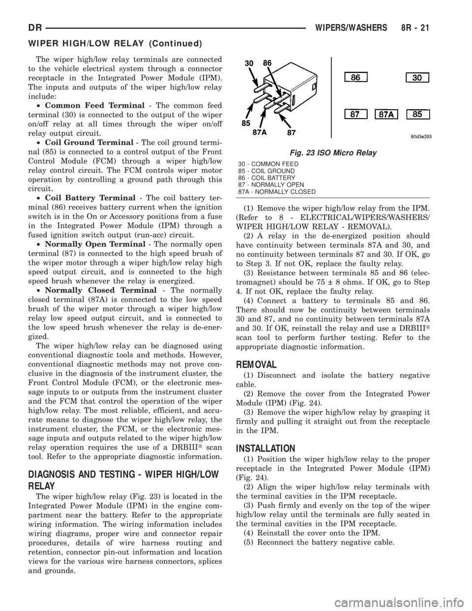
The wiper high/low relay terminals are connected
to the vehicle electrical system through a connector
receptacle in the Integrated Power Module (IPM).
The inputs and outputs of the wiper high/low relay
include:
²Common Feed Terminal- The common feed
terminal (30) is connected to the output of the wiper
on/off relay at all times through the wiper on/off
relay output circuit.
²Coil Ground Terminal- The coil ground termi-
nal (85) is connected to a control output of the Front
Control Module (FCM) through a wiper high/low
relay control circuit. The FCM controls wiper motor
operation by controlling a ground path through this
circuit.
²Coil Battery Terminal- The coil battery ter-
minal (86) receives battery current when the ignition
switch is in the On or Accessory positions from a fuse
in the Integrated Power Module (IPM) through a
fused ignition switch output (run-acc) circuit.
²Normally Open Terminal- The normally open
terminal (87) is connected to the high speed brush of
the wiper motor through a wiper high/low relay high
speed output circuit, and is connected to the high
speed brush whenever the relay is energized.
²Normally Closed Terminal- The normally
closed terminal (87A) is connected to the low speed
brush of the wiper motor through a wiper high/low
relay low speed output circuit, and is connected to
the low speed brush whenever the relay is de-ener-
gized.
The wiper high/low relay can be diagnosed using
conventional diagnostic tools and methods. However,
conventional diagnostic methods may not prove con-
clusive in the diagnosis of the instrument cluster, the
Front Control Module (FCM), or the electronic mes-
sage inputs to or outputs from the instrument cluster
and the FCM that control the operation of the wiper
high/low relay. The most reliable, efficient, and accu-
rate means to diagnose the wiper high/low relay, the
instrument cluster, the FCM, or the electronic mes-
sage inputs and outputs related to the wiper high/low
relay operation requires the use of a DRBIIItscan
tool. Refer to the appropriate diagnostic information.
DIAGNOSIS AND TESTING - WIPER HIGH/LOW
RELAY
The wiper high/low relay (Fig. 23) is located in the
Integrated Power Module (IPM) in the engine com-
partment near the battery. Refer to the appropriate
wiring information. The wiring information includes
wiring diagrams, proper wire and connector repair
procedures, details of wire harness routing and
retention, connector pin-out information and location
views for the various wire harness connectors, splices
and grounds.(1) Remove the wiper high/low relay from the IPM.
(Refer to 8 - ELECTRICAL/WIPERS/WASHERS/
WIPER HIGH/LOW RELAY - REMOVAL).
(2) A relay in the de-energized position should
have continuity between terminals 87A and 30, and
no continuity between terminals 87 and 30. If OK, go
to Step 3. If not OK, replace the faulty relay.
(3) Resistance between terminals 85 and 86 (elec-
tromagnet) should be 75 8 ohms. If OK, go to Step
4. If not OK, replace the faulty relay.
(4) Connect a battery to terminals 85 and 86.
There should now be continuity between terminals
30 and 87, and no continuity between terminals 87A
and 30. If OK, reinstall the relay and use a DRBIIIt
scan tool to perform further testing. Refer to the
appropriate diagnostic information.
REMOVAL
(1) Disconnect and isolate the battery negative
cable.
(2) Remove the cover from the Integrated Power
Module (IPM) (Fig. 24).
(3) Remove the wiper high/low relay by grasping it
firmly and pulling it straight out from the receptacle
in the IPM.
INSTALLATION
(1) Position the wiper high/low relay to the proper
receptacle in the Integrated Power Module (IPM)
(Fig. 24).
(2) Align the wiper high/low relay terminals with
the terminal cavities in the IPM receptacle.
(3) Push firmly and evenly on the top of the wiper
high/low relay until the terminals are fully seated in
the terminal cavities in the IPM receptacle.
(4) Reinstall the cover onto the IPM.
(5) Reconnect the battery negative cable.
Fig. 23 ISO Micro Relay
30 - COMMON FEED
85 - COIL GROUND
86 - COIL BATTERY
87 - NORMALLY OPEN
87A - NORMALLY CLOSED
DRWIPERS/WASHERS 8R - 21
WIPER HIGH/LOW RELAY (Continued)
Page 704 of 2895

8W-01 WIRING DIAGRAM INFORMATION
TABLE OF CONTENTS
page page
WIRING DIAGRAM INFORMATION
DESCRIPTION
DESCRIPTION - HOW TO USE WIRING
DIAGRAMS...........................1
DESCRIPTION - CIRCUIT INFORMATION....5
DESCRIPTION - CIRCUIT FUNCTIONS......6
DESCRIPTION - SECTION IDENTIFICATION
AND INFORMATION....................6
DESCRIPTION - CONNECTOR, GROUND
AND SPLICE INFORMATION..............7
WARNING
WARNINGS - GENERAL.................7
DIAGNOSIS AND TESTING - WIRING
HARNESS............................7
STANDARD PROCEDURE
STANDARD PROCEDURE -
ELECTROSTATIC DISCHARGE (ESD)
SENSITIVE DEVICES...................8
STANDARD PROCEDURE - TESTING OF
VOLTAGE POTENTIAL...................9
STANDARD PROCEDURE - TESTING FOR
CONTINUITY..........................9STANDARD PROCEDURE - TESTING FOR A
SHORT TO GROUND...................9
STANDARD PROCEDURE - TESTING FOR A
SHORT TO GROUND ON FUSES
POWERING SEVERAL LOADS...........10
STANDARD PROCEDURE - TESTING FOR A
VOLTAGE DROP......................10
SPECIAL TOOLS
WIRING/TERMINAL....................10
CONNECTOR
REMOVAL.............................11
INSTALLATION.........................11
DIODE
REMOVAL.............................14
INSTALLATION.........................14
TERMINAL
REMOVAL.............................14
INSTALLATION.........................14
WIRE
STANDARD PROCEDURE - WIRE SPLICING . . 15
WIRING DIAGRAM
INFORMATION
DESCRIPTION
DESCRIPTION - HOW TO USE WIRING
DIAGRAMS
DaimlerChrysler Corporation wiring diagrams are
designed to provide information regarding the vehi-
cles wiring content. In order to effectively use the
wiring diagrams to diagnose and repair
DaimlerChrysler Corporation vehicles, it is important
to understand all of their features and characteris-
tics.
Diagrams are arranged such that the power (B+)
side of the circuit is placed near the top of the page,
and the ground (B-) side of the circuit is placed near
the bottom of the page (Fig. 1).
All switches, components, and modules are shown
in the at rest position with the doors closed and the
key removed from the ignition (Fig. 2).Components are shown two ways. A solid line
around a component indicates that the component is
complete. A dashed line around the component indi-
cates that the component is being shown is not com-
plete. Incomplete components have a reference
number to indicate the page where the component is
shown complete.
It is important to realize that no attempt is made
on the diagrams to represent components and wiring
as they appear on the vehicle. For example, a short
piece of wire is treated the same as a long one. In
addition, switches and other components are shown
as simply as possible, with regard to function only.
SYMBOLS
International symbols are used throughout the wir-
ing diagrams. These symbols are consistent with
those being used around the world (Fig. 3).
DR8W-01 WIRING DIAGRAM INFORMATION 8W - 01 - 1