2003 DODGE RAM Ignition switch diagram
[x] Cancel search: Ignition switch diagramPage 710 of 2895

DESCRIPTION - CONNECTOR, GROUND AND
SPLICE INFORMATION
CAUTION: Not all connectors are serviced. Some
connectors are serviced only with a harness. A typ-
ical example might be the Supplemental Restraint
System connectors. Always check parts availability
before attempting a repair.
IDENTIFICATION
In-line connectors are identified by a number, as
follows:
²In-line connectors located in the engine compart-
ment are C100 series numbers
²In-line connectors located in the Instrument
Panel area are C200 series numbers.
²In-line connectors located in the body are C300
series numbers.
²Jumper harness connectors are C400 series
numbers.
²Grounds and ground connectors are identified
with a ªGº and follow the same series numbering as
the in-line connectors.
²Splices are identified with an ªSº and follow the
same series numbering as the in-line connectors.
²Component connectors are identified by the com-
ponent name instead of a number. Multiple connec-
tors on a component use a C1, C2, etc. identifier.
LOCATIONS
Section 8W-91 contains connector/ground/splice
location illustrations. The illustrations contain the
connector name (or number)/ground number/splice
number and component identification. Connector/
ground/splice location charts in section 8W-91 refer-
ence the figure numbers of the illustrations.
The abbreviation T/O is used in the component
location section to indicate a point in which the wir-
ing harness branches out to a component. The abbre-
viation N/S means Not Shown in the illustrations
WARNING
WARNINGS - GENERAL
WARNINGSprovide information to prevent per-
sonal injury and vehicle damage. Below is a list of
general warnings that should be followed any time a
vehicle is being serviced.
WARNING: ALWAYS WEAR SAFETY GLASSES FOR
EYE PROTECTION.
WARNING: USE SAFETY STANDS ANYTIME A PRO-
CEDURE REQUIRES BEING UNDER A VEHICLE.WARNING: BE SURE THAT THE IGNITION SWITCH
ALWAYS IS IN THE OFF POSITION, UNLESS THE
PROCEDURE REQUIRES IT TO BE ON.
WARNING: SET THE PARKING BRAKE WHEN
WORKING ON ANY VEHICLE. AN AUTOMATIC
TRANSMISSION SHOULD BE IN PARK. A MANUAL
TRANSMISSION SHOULD BE IN NEUTRAL.
WARNING: OPERATE THE ENGINE ONLY IN A
WELL-VENTILATED AREA.
WARNING: KEEP AWAY FROM MOVING PARTS
WHEN THE ENGINE IS RUNNING, ESPECIALLY THE
FAN AND BELTS.
WARNING: TO PREVENT SERIOUS BURNS, AVOID
CONTACT WITH HOT PARTS SUCH AS THE RADIA-
TOR, EXHAUST MANIFOLD(S), TAIL PIPE, CATA-
LYTIC CONVERTER AND MUFFLER.
WARNING: DO NOT ALLOW FLAME OR SPARKS
NEAR THE BATTERY. GASES ARE ALWAYS
PRESENT IN AND AROUND THE BATTERY.
WARNING: ALWAYS REMOVE RINGS, WATCHES,
LOOSE HANGING JEWELRY AND AVOID LOOSE
CLOTHING.
DIAGNOSIS AND TESTING - WIRING HARNESS
TROUBLESHOOTING TOOLS
When diagnosing a problem in an electrical circuit
there are several common tools necessary. These tools
are listed and explained below.
²Jumper Wire - This is a test wire used to con-
nect two points of a circuit. It can be used to bypass
an open in a circuit.
WARNING: NEVER USE A JUMPER WIRE ACROSS
A LOAD, SUCH AS A MOTOR, CONNECTED
BETWEEN A BATTERY FEED AND GROUND.
²Voltmeter - Used to check for voltage on a cir-
cuit. Always connect the black lead to a known good
ground and the red lead to the positive side of the
circuit.
CAUTION: Most of the electrical components used
in today's vehicles are Solid State. When checking
voltages in these circuits, use a meter with a 10 -
megohm or greater impedance rating.
DR8W-01 WIRING DIAGRAM INFORMATION 8W - 01 - 7
WIRING DIAGRAM INFORMATION (Continued)
Page 713 of 2895
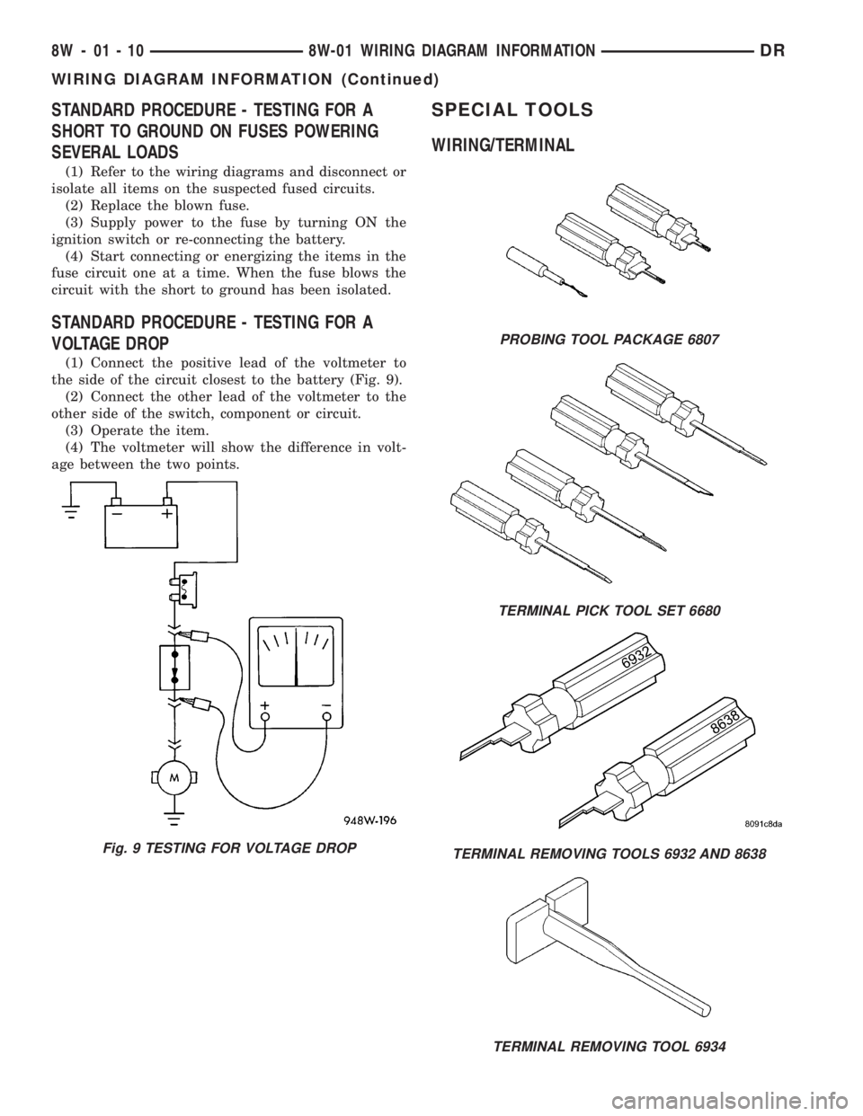
STANDARD PROCEDURE - TESTING FOR A
SHORT TO GROUND ON FUSES POWERING
SEVERAL LOADS
(1) Refer to the wiring diagrams and disconnect or
isolate all items on the suspected fused circuits.
(2) Replace the blown fuse.
(3) Supply power to the fuse by turning ON the
ignition switch or re-connecting the battery.
(4) Start connecting or energizing the items in the
fuse circuit one at a time. When the fuse blows the
circuit with the short to ground has been isolated.
STANDARD PROCEDURE - TESTING FOR A
VOLTAGE DROP
(1) Connect the positive lead of the voltmeter to
the side of the circuit closest to the battery (Fig. 9).
(2) Connect the other lead of the voltmeter to the
other side of the switch, component or circuit.
(3) Operate the item.
(4) The voltmeter will show the difference in volt-
age between the two points.
SPECIAL TOOLS
WIRING/TERMINAL
Fig. 9 TESTING FOR VOLTAGE DROP
PROBING TOOL PACKAGE 6807
TERMINAL PICK TOOL SET 6680
TERMINAL REMOVING TOOLS 6932 AND 8638
TERMINAL REMOVING TOOL 6934
8W - 01 - 10 8W-01 WIRING DIAGRAM INFORMATIONDR
WIRING DIAGRAM INFORMATION (Continued)
Page 1241 of 2895
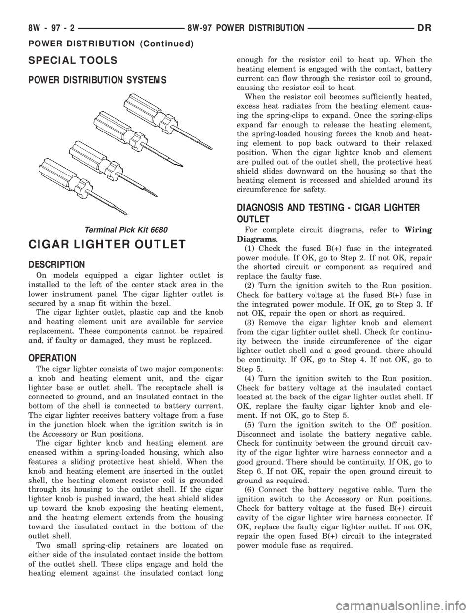
SPECIAL TOOLS
POWER DISTRIBUTION SYSTEMS
CIGAR LIGHTER OUTLET
DESCRIPTION
On models equipped a cigar lighter outlet is
installed to the left of the center stack area in the
lower instrument panel. The cigar lighter outlet is
secured by a snap fit within the bezel.
The cigar lighter outlet, plastic cap and the knob
and heating element unit are available for service
replacement. These components cannot be repaired
and, if faulty or damaged, they must be replaced.
OPERATION
The cigar lighter consists of two major components:
a knob and heating element unit, and the cigar
lighter base or outlet shell. The receptacle shell is
connected to ground, and an insulated contact in the
bottom of the shell is connected to battery current.
The cigar lighter receives battery voltage from a fuse
in the junction block when the ignition switch is in
the Accessory or Run positions.
The cigar lighter knob and heating element are
encased within a spring-loaded housing, which also
features a sliding protective heat shield. When the
knob and heating element are inserted in the outlet
shell, the heating element resistor coil is grounded
through its housing to the outlet shell. If the cigar
lighter knob is pushed inward, the heat shield slides
up toward the knob exposing the heating element,
and the heating element extends from the housing
toward the insulated contact in the bottom of the
outlet shell.
Two small spring-clip retainers are located on
either side of the insulated contact inside the bottom
of the outlet shell. These clips engage and hold the
heating element against the insulated contact longenough for the resistor coil to heat up. When the
heating element is engaged with the contact, battery
current can flow through the resistor coil to ground,
causing the resistor coil to heat.
When the resistor coil becomes sufficiently heated,
excess heat radiates from the heating element caus-
ing the spring-clips to expand. Once the spring-clips
expand far enough to release the heating element,
the spring-loaded housing forces the knob and heat-
ing element to pop back outward to their relaxed
position. When the cigar lighter knob and element
are pulled out of the outlet shell, the protective heat
shield slides downward on the housing so that the
heating element is recessed and shielded around its
circumference for safety.
DIAGNOSIS AND TESTING - CIGAR LIGHTER
OUTLET
For complete circuit diagrams, refer toWiring
Diagrams.
(1) Check the fused B(+) fuse in the integrated
power module. If OK, go to Step 2. If not OK, repair
the shorted circuit or component as required and
replace the faulty fuse.
(2) Turn the ignition switch to the Run position.
Check for battery voltage at the fused B(+) fuse in
the integrated power module. If OK, go to Step 3. If
not OK, repair the open or short as required.
(3) Remove the cigar lighter knob and element
from the cigar lighter outlet shell. Check for continu-
ity between the inside circumference of the cigar
lighter outlet shell and a good ground. there should
be continuity. If OK, go to Step 4. If not OK, go to
Step 5.
(4) Turn the ignition switch to the Run position.
Check for battery voltage at the insulated contact
located at the back of the cigar lighter outlet shell. If
OK, replace the faulty cigar lighter knob and ele-
ment. If not OK, go to Step 5.
(5) Turn the ignition switch to the Off position.
Disconnect and isolate the battery negative cable.
Check for continuity between the ground circuit cav-
ity of the cigar lighter wire harness connector and a
good ground. There should be continuity. If OK, go to
Step 6. If not OK, repair the open ground circuit to
ground as required.
(6) Connect the battery negative cable. Turn the
ignition switch to the Accessory or Run positions.
Check for battery voltage at the fused B(+) circuit
cavity of the cigar lighter wire harness connector. If
OK, replace the faulty cigar lighter outlet. If not OK,
repair the open fused B(+) circuit to the integrated
power module fuse as required.Terminal Pick Kit 6680
8W - 97 - 2 8W-97 POWER DISTRIBUTIONDR
POWER DISTRIBUTION (Continued)
Page 1246 of 2895
INSTALLATION
(1) Turn the ignition switch to the Off position.
(2) Remove the Integrated Power Module cover.
(3) To install the IOD fuse, use a thumb to press
the IOD fuse holder unit in fuse cavity # 51 firmly
into the Integrated Power Module.
(4) Install the Integrated Power Module cover.
POWER OUTLET
DESCRIPTION
Two power outlets are utilized on this model. One
in the instrument panel center lower bezel and the
other in the center console. The power outlet bases
are secured by a snap fit within the instrument
panel or trim panel. A plastic protective cap snaps
into the power outlet base when the power outlet is
not being used, and hangs from the power outlet base
mount by an integral bail strap while the power out-
let is in use.
The power outlet receptacle unit and the accessory
power outlet protective cap are available for service.
The power outlet receptacle cannot be repaired and,
if faulty or damaged, it must be replaced.
OPERATION
The power outlet base or receptacle shell is con-
nected to ground, and an insulated contact in the
bottom of the shell is connected to battery current.
The power outlet receives battery voltage from a fuse
in the integrated power module at all times.
While the power outlet is very similar to a cigar
lighter base unit, it does not include the two small
spring-clip retainers inside the bottom of the recepta-
cle shell that are used to secure the cigar lighter
heating element to the insulated contact.
DIAGNOSIS AND TESTING - POWER OUTLET
For complete circuit diagrams, refer toWiring
Diagrams.
(1) Check the fused B(+) fuse in the integrated
power module. If OK, go to Step 2. If not OK, repair
the shorted circuit or component as required and
replace the faulty fuse.
(2) Check for battery voltage at the fused B(+) fuse
in the integrated power module. If OK, go to Step 3.
If not OK, repair the open fused B(+) circuit to the
battery as required.
(3) Remove the plastic protective cap from the
power outlet receptacle. Check for continuity between
the inside circumference of the power outlet recepta-
cle and a good ground. There should be continuity. If
OK, go to Step 4. If not OK, go to Step 5.(4) Check for battery voltage at the insulated con-
tact located at the back of the power outlet recepta-
cle. If not OK, go to Step 5.
(5) Disconnect and isolate the battery negative
cable. Remove the power outlet receptacle from the
instrument panel. Disconnect the wire harness con-
nector from the power outlet receptacle. Check for
continuity between the ground circuit cavity of the
power outlet wire harness connector and a good
ground. There should be continuity. If OK, go to Step
6. If not OK, repair the open ground circuit to ground
as required.
(6) Connect the battery negative cable. Check for
battery voltage at the fused B(+) circuit cavity of the
power outlet wire harness connector. If OK, replace
the faulty power outlet receptacle. If not OK, repair
the open fused B(+) circuit to the integrated power
module fuse as required.
REMOVAL
(1) Disconnect and isolate the battery negative
cable.
(2) Pull the cigar lighter knob and element out of
the cigar lighter receptacle base, or unsnap the pro-
tective cap from the power outlet receptacle base.
(3) Look inside the cigar lighter or power outlet
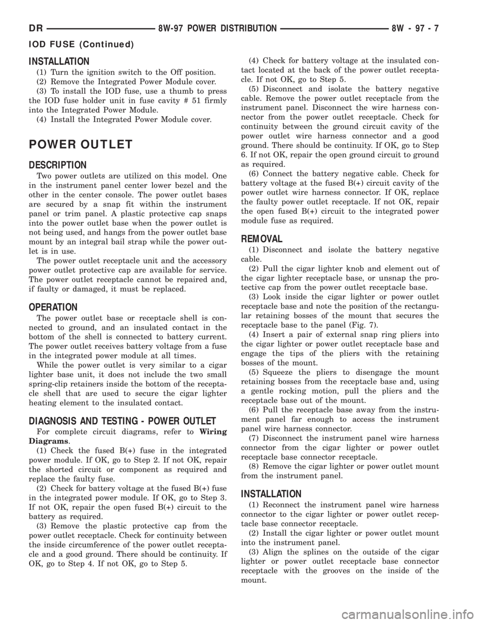
receptacle base and note the position of the rectangu-
lar retaining bosses of the mount that secures the
receptacle base to the panel (Fig. 7).
(4) Insert a pair of external snap ring pliers into
the cigar lighter or power outlet receptacle base and
engage the tips of the pliers with the retaining
bosses of the mount.
(5) Squeeze the pliers to disengage the mount
retaining bosses from the receptacle base and, using
a gentle rocking motion, pull the pliers and the
receptacle base out of the mount.
(6) Pull the receptacle base away from the instru-
ment panel far enough to access the instrument
panel wire harness connector.
(7) Disconnect the instrument panel wire harness
connector from the cigar lighter or power outlet
receptacle base connector receptacle.
(8) Remove the cigar lighter or power outlet mount
from the instrument panel.
INSTALLATION
(1) Reconnect the instrument panel wire harness
connector to the cigar lighter or power outlet recep-
tacle base connector receptacle.
(2) Install the cigar lighter or power outlet mount
into the instrument panel.
(3) Align the splines on the outside of the cigar
lighter or power outlet receptacle base connector
receptacle with the grooves on the inside of the
mount.
DR8W-97 POWER DISTRIBUTION 8W - 97 - 7
IOD FUSE (Continued)
Page 1247 of 2895
(4) Press firmly on the cigar lighter or power out-
let receptacle base until the retaining bosses of the
mount are fully engaged in their receptacles.
(5) Install the cigar lighter knob and element into
the cigar lighter receptacle base, or the protective cap
into the power outlet receptacle base.
(6) Reconnect the battery negative cable.
RELAY
DESCRIPTION
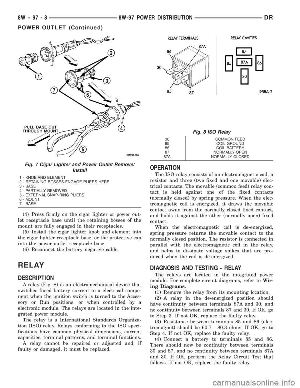
A relay (Fig. 8) is an electromechanical device that
switches fused battery current to a electrical compo-
nent when the ignition switch is turned to the Acces-
sory or Run positions, or when controlled by a
electronic module. The relays are located in the inte-
grated power module.
The relay is a International Standards Organiza-
tion (ISO) relay. Relays conforming to the ISO speci-
fications have common physical dimensions, current
capacities, terminal patterns, and terminal functions.
A relay cannot be repaired or adjusted and, if
faulty or damaged, it must be replaced.
OPERATION
The ISO relay consists of an electromagnetic coil, a
resistor and three (two fixed and one movable) elec-
trical contacts. The movable (common feed) relay con-
tact is held against one of the fixed contacts
(normally closed) by spring pressure. When the elec-
tromagnetic coil is energized, it draws the movable
contact away from the normally closed fixed contact,
and holds it against the other (normally open) fixed
contact.
When the electromagnetic coil is de-energized,
spring pressure returns the movable contact to the
normally closed position. The resistor is connected in
parallel with the electromagnetic coil in the relay,
and helps to dissipate voltage spikes that are pro-
duced when the coil is de-energized.
DIAGNOSIS AND TESTING - RELAY
The relays are located in the integrated power
module. For complete circuit diagrams, refer toWir-
ing Diagrams.
(1) Remove the relay from its mounting location.
(2) A relay in the de-energized position should
have continuity between terminals 87A and 30, and
no continuity between terminals 87 and 30. If OK, go
to Step 3. If not OK, replace the faulty relay.
(3) Resistance between terminals 85 and 86 (elec-
tromagnet) should be 60.7 - 80.3 ohms. If OK, go to
Step 4. If not OK, replace the faulty relay.
(4) Connect a battery to terminals 85 and 86.
There should now be continuity between terminals
30 and 87, and no continuity between terminals 87A
and 30. If OK, perform the Relay Circuit Test that
follows. If not OK, replace the faulty relay.
Fig. 7 Cigar Lighter and Power Outlet Remove/
Install
1 - KNOB AND ELEMENT
2 - RETAINING BOSSES-ENGAGE PLIERS HERE
3 - BASE
4 - PARTIALLY REMOVED
5 - EXTERNAL SNAP-RING PLIERS
6 - MOUNT
7 - BASE
Fig. 8 ISO Relay
30 COMMON FEED
85 COIL GROUND
86 COIL BATTERY
87 NORMALLY OPEN
87A NORMALLY CLOSED
8W - 97 - 8 8W-97 POWER DISTRIBUTIONDR
POWER OUTLET (Continued)
Page 1804 of 2895
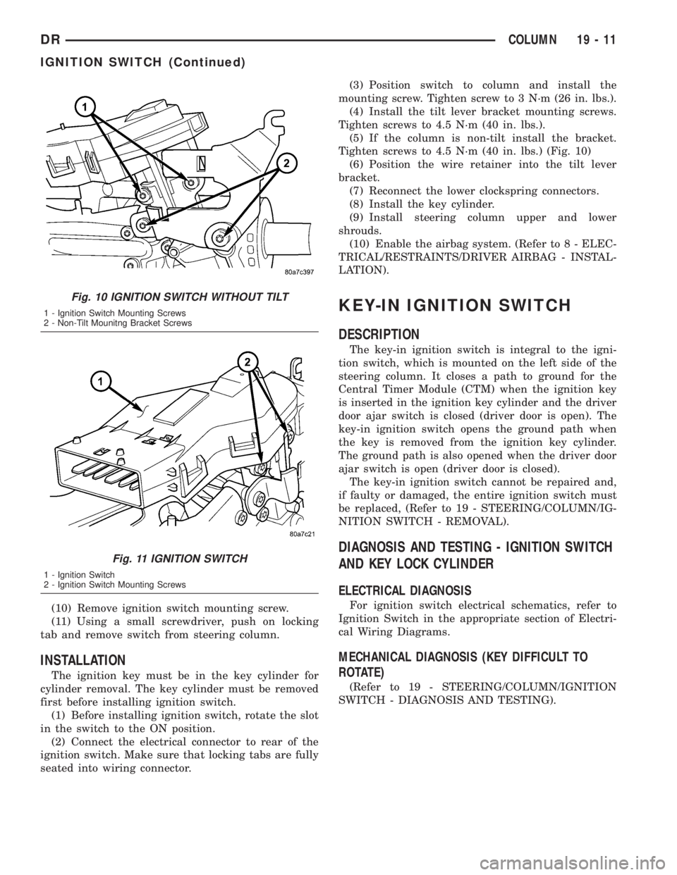
(10) Remove ignition switch mounting screw.
(11) Using a small screwdriver, push on locking
tab and remove switch from steering column.
INSTALLATION
The ignition key must be in the key cylinder for
cylinder removal. The key cylinder must be removed
first before installing ignition switch.
(1) Before installing ignition switch, rotate the slot
in the switch to the ON position.
(2) Connect the electrical connector to rear of the
ignition switch. Make sure that locking tabs are fully
seated into wiring connector.(3) Position switch to column and install the
mounting screw. Tighten screw to 3 N´m (26 in. lbs.).
(4) Install the tilt lever bracket mounting screws.
Tighten screws to 4.5 N´m (40 in. lbs.).
(5) If the column is non-tilt install the bracket.
Tighten screws to 4.5 N´m (40 in. lbs.) (Fig. 10)
(6) Position the wire retainer into the tilt lever
bracket.
(7) Reconnect the lower clockspring connectors.
(8) Install the key cylinder.
(9) Install steering column upper and lower
shrouds.
(10) Enable the airbag system. (Refer to 8 - ELEC-
TRICAL/RESTRAINTS/DRIVER AIRBAG - INSTAL-
LATION).
KEY-IN IGNITION SWITCH
DESCRIPTION
The key-in ignition switch is integral to the igni-
tion switch, which is mounted on the left side of the
steering column. It closes a path to ground for the
Central Timer Module (CTM) when the ignition key
is inserted in the ignition key cylinder and the driver
door ajar switch is closed (driver door is open). The
key-in ignition switch opens the ground path when
the key is removed from the ignition key cylinder.
The ground path is also opened when the driver door
ajar switch is open (driver door is closed).
The key-in ignition switch cannot be repaired and,
if faulty or damaged, the entire ignition switch must
be replaced, (Refer to 19 - STEERING/COLUMN/IG-
NITION SWITCH - REMOVAL).
DIAGNOSIS AND TESTING - IGNITION SWITCH
AND KEY LOCK CYLINDER
ELECTRICAL DIAGNOSIS
For ignition switch electrical schematics, refer to
Ignition Switch in the appropriate section of Electri-
cal Wiring Diagrams.
MECHANICAL DIAGNOSIS (KEY DIFFICULT TO
ROTATE)
(Refer to 19 - STEERING/COLUMN/IGNITION
SWITCH - DIAGNOSIS AND TESTING).
Fig. 10 IGNITION SWITCH WITHOUT TILT
1 - Ignition Switch Mounting Screws
2 - Non-Tilt Mounitng Bracket Screws
Fig. 11 IGNITION SWITCH
1 - Ignition Switch
2 - Ignition Switch Mounting Screws
DRCOLUMN 19 - 11
IGNITION SWITCH (Continued)
Page 2788 of 2895
NOTE: The air gap is determined by the spacer
shims. When installing an original, or a new clutch
assembly, try the original shims first. When install-
ing a new clutch onto a compressor that previously
did not have a clutch, use a 1.0, 0.50, and 0.13 mil-
limeter (0.040, 0.020, and 0.005 inch) shims from the
new clutch hardware package that is provided with
the new clutch.
(9) To complete the procedure, (Refer to 24 -
HEATING & AIR CONDITIONING/PLUMBING/A/C
COMPRESSOR - INSTALLATION).
A/C COMPRESSOR CLUTCH
RELAY
DESCRIPTION
The compressor clutch relay is a International
Standards Organization (ISO) micro-relay. The termi-
nal designations and functions are the same as a con-
ventional ISO relay. However, the micro-relay
terminal orientation (footprint) is different, the cur-
rent capacity is lower, and the relay case dimensions
are smaller than those of the conventional ISO relay.
The compressor clutch relay is located in the Power
Distribution Center (PDC) in the engine compart-
ment. Refer to the PDC label for relay identification
and location.
OPERATION
The compressor clutch relay is a electromechanical
device that switches battery current to the compres-
sor clutch coil when the Powertrain Control Module
(PCM) grounds the coil side of the relay. The PCM
responds to inputs from the A/C Heater mode control
switch, the A/C low pressure switch, and the A/C
high pressure switch. (Refer to 24 - HEATING & AIR
CONDITIONING/CONTROLS/A/C COMPRESSOR
CLUTCH RELAY - DIAGNOSIS AND TESTING)
The compressor clutch relay cannot be repaired
and, if faulty or damaged, it must be replaced.
DIAGNOSIS AND TESTING - COMPRESSOR
CLUTCH RELAY
RELAY TEST
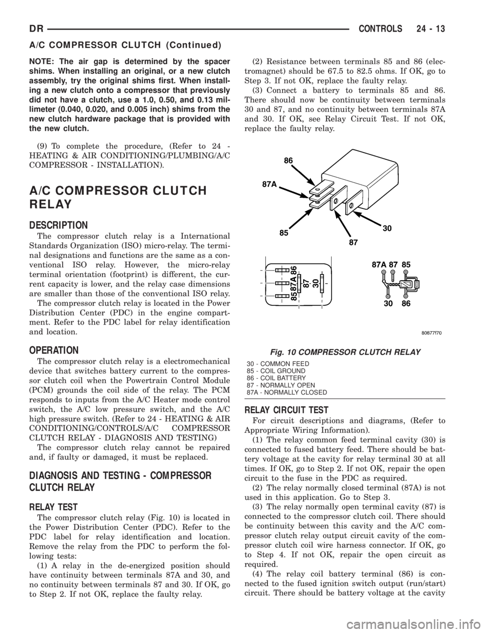
The compressor clutch relay (Fig. 10) is located in
the Power Distribution Center (PDC). Refer to the
PDC label for relay identification and location.
Remove the relay from the PDC to perform the fol-
lowing tests:
(1) A relay in the de-energized position should
have continuity between terminals 87A and 30, and
no continuity between terminals 87 and 30. If OK, go
to Step 2. If not OK, replace the faulty relay.(2) Resistance between terminals 85 and 86 (elec-
tromagnet) should be 67.5 to 82.5 ohms. If OK, go to
Step 3. If not OK, replace the faulty relay.
(3) Connect a battery to terminals 85 and 86.
There should now be continuity between terminals
30 and 87, and no continuity between terminals 87A
and 30. If OK, see Relay Circuit Test. If not OK,
replace the faulty relay.
RELAY CIRCUIT TEST
For circuit descriptions and diagrams, (Refer to
Appropriate Wiring Information).
(1) The relay common feed terminal cavity (30) is
connected to fused battery feed. There should be bat-
tery voltage at the cavity for relay terminal 30 at all
times. If OK, go to Step 2. If not OK, repair the open
circuit to the fuse in the PDC as required.
(2) The relay normally closed terminal (87A) is not
used in this application. Go to Step 3.
(3) The relay normally open terminal cavity (87) is
connected to the compressor clutch coil. There should
be continuity between this cavity and the A/C com-
pressor clutch relay output circuit cavity of the com-
pressor clutch coil wire harness connector. If OK, go
to Step 4. If not OK, repair the open circuit as
required.
(4) The relay coil battery terminal (86) is con-
nected to the fused ignition switch output (run/start)
circuit. There should be battery voltage at the cavity
Fig. 10 COMPRESSOR CLUTCH RELAY
30 - COMMON FEED
85 - COIL GROUND
86 - COIL BATTERY
87 - NORMALLY OPEN
87A - NORMALLY CLOSED
DRCONTROLS 24 - 13
A/C COMPRESSOR CLUTCH (Continued)
Page 2865 of 2895
CUSHION / COVER - FRONT -
INSTALLATION, SEAT.................23-83
CUSHION / COVER - FRONT -
INSTALLATION, SEAT BACK............23-83
CUSHION / COVER - FRONT - REMOVAL,
SEAT ..............................23-83
CUSHION / COVER - FRONT - REMOVAL,
SEAT BACK.........................23-83
CUSHION / COVER - REAR -
INSTALLATION, SEAT.................23-85
CUSHION / COVER - REAR -
INSTALLATION, SEAT BACK............23-85
CUSHION / COVER - REAR - REMOVAL,
SEAT ..............................23-85
CUSHION / COVER - REAR - REMOVAL,
SEAT BACK.........................23-85
CUSHION - INSTALLATION, CENTER
SEAT ..............................23-80
CUSHION - REMOVAL, CENTER SEAT.....23-80
CUSHION COVER - INSTALLATION,
CENTER SEAT.......................23-81
CUSHION COVER - REMOVAL, CENTER
SEAT ..............................23-81
CUSHION FRAME - REAR -
INSTALLATION, SEAT.................23-85
CUSHION FRAME - REAR - REMOVAL,
SEAT ..............................23-85
CUSTOMER PREFERENCES - STANDARD
PROCEDURE, RKE TRANSMITTER........8N-9
CV JOINT-INNER - INSTALLATION........3-16
CV JOINT-INNER - REMOVAL............3-16
CV JOINT-OUTER - INSTALLATION........3-13
CV JOINT-OUTER - REMOVAL............3-13
CYLINDER - DESCRIPTION, MASTER......5-19
CYLINDER - DIAGNOSIS AND TESTING,
IGNITION SWITCH AND KEY LOCK.......19-11
CYLINDER - INSTALLATION, KEY........19-12
CYLINDER - INSTALLATION, LOAD
FLOOR SUPPORT....................23-73
CYLINDER - INSTALLATION, LOCK.......23-24
CYLINDER - INSTALLATION, SUPPORT....23-49
CYLINDER - OPERATION, MASTER........5-20
CYLINDER - REMOVAL, KEY............19-12
CYLINDER - REMOVAL, LOAD FLOOR
SUPPORT..........................23-73
CYLINDER - REMOVAL, LOCK...........23-24
CYLINDER - REMOVAL, SUPPORT.......23-48
CYLINDER BLEEDING - STANDARD
PROCEDURE, MASTER.................5-20
CYLINDER BLOCK REFACING -
STANDARD PROCEDURE...............9-312
CYLINDER BORE - DE-GLAZE -
STANDARD PROCEDURE...............9-313
CYLINDER BORE HONING - STANDARD
PROCEDURE..........9-126,9-233,9-360,9-37
CYLINDER BORE REPAIR - STANDARD
PROCEDURE........................9-313
CYLINDER COMBUSTION PRESSURE
LEAKAGE - DIAGNOSIS AND TESTING....9-182,
9-231,9-359,9-8,9-92
CYLINDER COMPRESSION PRESSURE -
DIAGNOSIS AND TESTING . . . 9-182,9-231,9-359,
9-8,9-92
CYLINDER COMPRESSION/LEAKAGE
TESTS - DIAGNOSIS AND TESTING......9-288
CYLINDER HEAD - CLEANING . 9-195,9-300,9-372
CYLINDER HEAD - DESCRIPTION . . 9-106,9-243,
9-298,9-370
CYLINDER HEAD - INSPECTION....9-195,9-301,
9-372
CYLINDER HEAD - INSTALLATION . . 9-195,9-372
CYLINDER HEAD - INSTALLATION, LEFT . . 9-110
CYLINDER HEAD - INSTALLATION,
RIGHT.............................9-111
CYLINDER HEAD - LEFT - INSTALLATION . . . 9-23
CYLINDER HEAD - LEFT - REMOVAL......9-21
CYLINDER HEAD - OPERATION.....9-194,9-243
CYLINDER HEAD - REMOVAL . 9-195,9-298,9-371
CYLINDER HEAD - REMOVAL, LEFT......9-106
CYLINDER HEAD - REMOVAL, RIGHT.....9-108
CYLINDER HEAD - RIGHT -
INSTALLATION
........................9-32
CYLINDER HEAD - RIGHT - REMOVAL
.....9-32
CYLINDER HEAD COVER -
INSTALLATION
.......................9-304
CYLINDER HEAD COVER - REMOVAL
.....9-304
CYLINDER HEAD COVER GASKET -
DESCRIPTION
.......................9-243CYLINDER HEAD COVER GASKET -
OPERATION.........................9-243
CYLINDER HEAD COVER(S) - CLEANING . . 9-245,
9-374
CYLINDER HEAD COVER(S) -
DESCRIPTION..............9-121,9-26,9-373
CYLINDER HEAD COVER(S) -
INSPECTION...................9-245,9-374
CYLINDER HEAD COVER(S) -
INSTALLATION....9-196,9-245,9-27,9-36,9-374
CYLINDER HEAD COVER(S) - REMOVAL . . 9-196,
9-245,9-26,9-35,9-373
CYLINDER HEAD GASKET - DIAGNOSIS
AND TESTING........................9-20
CYLINDER HEAD GASKET FAILURE -
DIAGNOSIS AND TESTING . . . 9-194,9-243,9-370
CYLINDER/POWER BOOSTER -
DIAGNOSIS AND TESTING, MASTER......5-20
DAM - INSTALLATION, FRONT AIR........13-2
DAM - REMOVAL, FRONT AIR...........13-2
DAMAGED OR WORN THREADS -
STANDARD PROCEDURE, REPAIR . . 9-186,9-232,
9-289,9-361,9-9,9-93
DAMPER - INSPECTION, VIBRATION.....9-335
DAMPER - INSTALLATION..............19-35
DAMPER - INSTALLATION, VIBRATION . . . 9-142,
9-209,9-263,9-335,9-392,9-55
DAMPER - REMOVAL.................19-35
DAMPER - REMOVAL, VIBRATION . . 9-141,9-209,
9-263,9-335,9-392,9-54
DATA LINK CONNECTOR - DESCRIPTION . . . 8E-3
DATA LINK CONNECTOR - OPERATION......8E-3
DATA PLATE - DESCRIPTION, ENGINE....9-297
DAY / NIGHT MIRROR - DESCRIPTION,
AUTOMATIC........................8N-12
DAY / NIGHT MIRROR - DIAGNOSIS AND
TESTING, AUTOMATIC................8N-12
DAY / NIGHT MIRROR - OPERATION,
AUTOMATIC........................8N-12
DAY / NIGHT MIRROR - REMOVAL,
AUTOMATIC........................8N-13
DEFINITION - DESCRIPTION, TRIP........25-4
DEFROST DOOR - INSTALLATION........24-27
DEFROST DOOR - INSTALLATION, FLOOR . 24-30
DEFROST DOOR - REMOVAL...........24-27
DEFROST DOOR - REMOVAL, FLOOR.....24-30
DEFROST DOOR ACTUATOR -
INSTALLATION, FLOOR................24-20
DEFROST DOOR ACTUATOR - REMOVAL,
FLOOR.............................24-19
DEGAS CONTAINER-3.7L/4.7L -
DESCRIPTION, COOLANT...............7-38
DEGAS CONTAINER-3.7L/4.7L -
INSTALLATION, COOLANT...............7-39
DEGAS CONTAINER-3.7L/4.7L -
OPERATION, COOLANT.................7-38
DEGAS CONTAINER-3.7L/4.7L -
REMOVAL, COOLANT..................7-39
DE-GLAZE - STANDARD PROCEDURE,
CYLINDER BORE.....................9-313
DEMAGNETIZING - STANDARD
PROCEDURE, COMPASS...............8M-4
DEPLOYMENT - STANDARD
PROCEDURE, SERVICE AFTER A
SUPPLEMENTAL RESTRAINT
............8O-7
DETECTION ASSY - DESCRIPTION,
NATURAL VAC LEAK
..................25-23
DETECTION ASSY - INSTALLATION,
NATURAL VAC LEAK
..................25-24
DETECTION ASSY - OPERATION,
NATURAL VAC LEAK
..................25-23
DETECTION ASSY - REMOVAL, NATURAL
VAC LEAK
..........................25-24
DETECTION PUMP - DESCRIPTION, LEAK
. 25-13
DETECTION PUMP - INSTALLATION,
LEAK
..............................25-16
DETECTION PUMP - OPERATION, LEAK
. . . 25-14
DETECTION PUMP - REMOVAL, LEAK
....25-16
DEVICES - STANDARD PROCEDURE,
ELECTROSTATIC DISCHARGE (ESD)
SENSITIVE
........................8W-01-8
DIAGNOSTIC TROUBLE CODES -
DESCRIPTION
........................25-1
DIAGNOSTICS (OBD) - DIAGNOSIS AND
TESTING, ON-BOARD
...................7-5
DIAGRAMS - DESCRIPTION, HOW TO
USE WIRING
......................8W-01-1DIAGRAMS - HYDRAULIC SCHEMATICS,
SCHEMATICS...........21-175,21-355,21-513
DIESEL - CLEANING, RADIATOR - 5.9L....7-60
DIESEL - CLEANING, RADIATOR FAN -
5.9L................................7-41
DIESEL - CLEANING, WATER PUMP -
5.9L................................7-67
DIESEL - DESCRIPTION...............14-73
DIESEL - DESCRIPTION, 5.9L............11-2
DIESEL - DESCRIPTION, BELT
TENSIONERS - 5.9L...................7-24
DIESEL - DESCRIPTION, COOLING
SYSTEM FLOW - 5.9L...................7-2
DIESEL - DESCRIPTION, ENGINE 5.9L....9-282
DIESEL - DESCRIPTION, ENGINE BLOCK
HEATER - 5.9L........................7-43
DIESEL - DESCRIPTION, ENGINE
COOLANT THERMOSTAT - 5.9L...........7-52
DIESEL - DESCRIPTION, FAN DRIVE
VISCOUS CLUTCH - 5.9L...............7-55
DIESEL - DESCRIPTION, RADIATOR -
5.9L................................7-59
DIESEL - DESCRIPTION, TRANS COOLER
- 5.9L..............................7-73
DIESEL - DESCRIPTION, WATER PUMP -
5.9L................................7-67
DIESEL - FUEL INJECTOR FIRING ORDER . 14-60
DIESEL - FUEL SYSTEM PRESSURE......14-60
DIESEL - INSPECTION, RADIATOR - 5.9L . . . 7-60
DIESEL - INSPECTION, RADIATOR FAN -
5.9L................................7-41
DIESEL - INSPECTION, TAILPIPE - 5.9L....11-9
DIESEL - INSPECTION, WATER PUMP -
5.9L................................7-68
DIESEL - INSTALLATION...............14-74
DIESEL - INSTALLATION.....19-25,19-30,19-41
DIESEL - INSTALLATION, BELT
TENSIONERS - 5.9L...................7-25
DIESEL - INSTALLATION, DRIVE BELTS -
5.9L................................7-34
DIESEL - INSTALLATION, ENGINE BLOCK
HEATER - 5.9L........................7-44
DIESEL - INSTALLATION, ENGINE
COOLANT THERMOSTAT - 5.9L...........7-53
DIESEL - INSTALLATION, EXCEPT........14-22
DIESEL - INSTALLATION, MUFFLER -
5.9L................................11-9
DIESEL - INSTALLATION, RADIATOR -
5.9L................................7-60
DIESEL - INSTALLATION, RADIATOR FAN
- 5.9L..............................7-41
DIESEL - INSTALLATION, TAILPIPE - 5.9L . . 11-9
DIESEL - INSTALLATION, WATER PUMP -
5.9L................................7-68
DIESEL - OPERATION, BELT
TENSIONERS - 5.9L...................7-24
DIESEL - OPERATION, ENGINE BLOCK
HEATER - 5.9L........................7-43
DIESEL - OPERATION, ENGINE COOLANT
THERMOSTAT - 5.9L...................7-52
DIESEL - OPERATION, FAN DRIVE
VISCOUS CLUTCH - 5.9L...............7-55
DIESEL - OPERATION, RADIATOR - 5.9L . . . 7-59
DIESEL - OPERATION, TRANS COOLER -
5.9L................................7-74
DIESEL - OPERATION, WATER PUMP -
5.9L................................7-67
DIESEL - REMOVAL...................14-73
DIESEL - REMOVAL.........19-24,19-30,19-40
DIESEL - REMOVAL, BELT TENSIONERS -
5.9L................................7-25
DIESEL - REMOVAL, DRIVE BELTS - 5.9L . . 7-34
DIESEL - REMOVAL, ENGINE BLOCK
HEATER - 5.9L........................7-43
DIESEL - REMOVAL, ENGINE COOLANT
THERMOSTAT - 5.9L...................7-53
DIESEL - REMOVAL, EXCEPT...........14-20
DIESEL - REMOVAL, MUFFLER - 5.9L.....11-9
DIESEL - REMOVAL, RADIATOR - 5.9L.....7-59
DIESEL - REMOVAL, RADIATOR FAN -
5.9L
................................7-41
DIESEL - REMOVAL, TAILPIPE - 5.9L
......11-9
DIESEL - REMOVAL, WATER PUMP -
5.9L
................................7-67
DIESEL ENGINE - DESCRIPTION, FUEL
REQUIREMENTS
.......................0-1
DIESEL ENGINE - DIAGNOSIS AND
TESTING
............................11-3
10 INDEXDR
Description Group-Page Description Group-Page Description Group-Page