2003 DODGE RAM electrical
[x] Cancel search: electricalPage 271 of 2895

then opens the outlet valve, which also opens the
return circuit to the accumulators. Fluid pressure is
allowed to bleed off (decrease) as needed to prevent
wheel lock.
Once the period of high wheel slip has ended, the
CAB closes the outlet valve and begins a pressure
increase or hold cycle as needed.
PRESSURE HOLD
Both solenoid valves are closed in the pressure
hold cycle but only the inlet valve is energized. Fluid
apply pressure in the control channel is maintained
at a constant rate. The CAB maintains the hold cycle
until sensor inputs indicate a pressure change is nec-
essary.
PRESSURE INCREASE
The inlet valve is open and the outlet valve is
closed during the pressure increase cycle. The pres-
sure increase cycle is used to reapply thew brakes.
This cycle controls re-application of fluid apply pres-
sure.
REMOVAL
(1) Install a prop rod on the brake pedal to keep
pressure on the brake system.
(2) Disconnect the battery cables from the battery.
(3) Remove the battery.
(4) Disconnect the two electrical harness connec-
tors (Fig. 5).
(5) Remove the five brake lines from the HCU
(Fig. 5).
(6) Remove HCU/CAB mounting bolts and remove
the HCU/CAB (Fig. 5).
INSTALLATION
NOTE: If the CAB is being replaced with a new CAB
is must be reprogrammed with the use of a DRB III.
(1) Install HCU/CAB on the mounts and Tighten
the bolts to 15N´m (11 ft. lbs.) (Fig. 5).
(2) Install the five brake lines to the HCU and
tighten to 19 N´m (170 in. lbs.) (Fig. 5).
(3) Install the two electrical harness connectors to
the HCU/CAB and push down on the release to
secure the connectors.
(4) Install the battery.
(5) Install the battery cables to the battery.
(6) Remove the prop rod on the brake pedal.
(7) Bleed ABS brake system (Refer to 5 - BRAKES
- STANDARD PROCEDURE).
RWAL VALVE
DESCRIPTION
Rear Wheel Antilock (RWAL) brake system is stan-
dard equipment on 1500 series vehicles. The RWAL
brake system is designed to prevent rear wheel
lock-up on virtually all types of road surfaces. RWAL
braking is desirable because a vehicle which is
stopped without locking the rear wheels will retain
directional stability. This allows the driver to retain
greater control of the vehicle during braking.
The valve is located on the drivers side inner
fender under the hood. The valve modulates hydrau-
lic pressure to the rear brakes.
The RWAL components include:
²RWAL Valve
²Controller Antilock brake (CAB)
²Rear Wheel Speed Sensor (WSS)
OPERATION
When the brakes are applied, hydraulic fluid is
routed from the master cylinder's secondary circuit to
the RWAL valve. From there hydraulic fluid is routed
to the rear brakes. The Controller Antilock Brake
(CAB) contains an Electronic Variable Brake Propor-
tioning (EVBP) control algorithm, which proportions
the applied braking force to the rear wheels during
braking. The EVBP function of the RWAL system
takes the place of a conventional hydraulic propor-
tioning valve. The CAB monitors the rear wheel
speed through the rear wheel speed sensor and cal-
culates an estimated vehicle deceleration. When an
established deceleration threshold is exceeded, an
isolation valve is closed to hold the applied brake
pressure to the rear brakes constant. Upon further
increases in the estimated vehicle deceleration, the
isolation valve is selectively opened to increase rear
Fig. 5 HYDRAULIC CONTROL UNIT
1 - HYDRAULIC CONTROL UNIT
2 - MOUNTING BOLTS
5 - 44 BRAKES - ABSDR
HCU (HYDRAULIC CONTROL UNIT) (Continued)
Page 272 of 2895

brake pressure in proportion to the front brake pres-
sure. If impending rear wheel lock-up is sensed, the
CAB signals the RWAL valve to modulate hydraulic
brake pressure to the rear wheels to prevent lock-up.
NORMAL BRAKING Since the RWAL valve also
performs the EVBP or proportioning function, vehicle
deceleration under normal braking may be sufficient
to trigger the EVBP function of the RWAL system
without full RWAL activity as would normally occur
during an impending rear wheel lock-up. As previ-
ously mentioned, the isolation valve is selectively
closed and opened to increase rear brake pressure in
proportion to the front brake pressure under EVBP
control. Slight brake pedal pulsations may be noticed
as the isolation valve is opened.
REMOVAL
(1) Install a prop rod on the brake pedal to keep
pressure on the brake system.
(2) Disconnect the battery cables from the battery.
(3) Remove the battery.
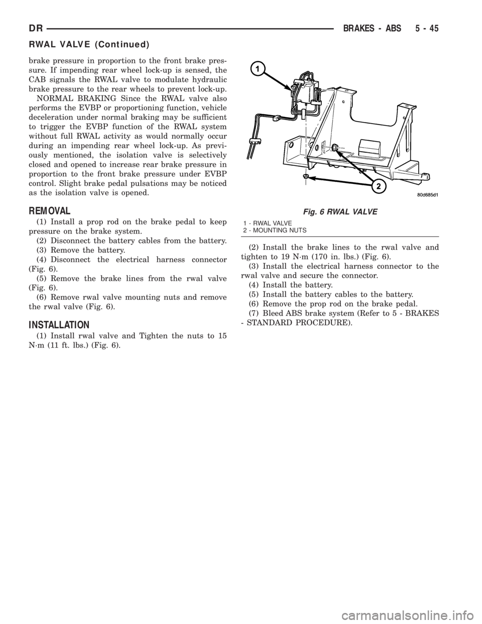
(4) Disconnect the electrical harness connector
(Fig. 6).
(5) Remove the brake lines from the rwal valve
(Fig. 6).
(6) Remove rwal valve mounting nuts and remove
the rwal valve (Fig. 6).
INSTALLATION
(1) Install rwal valve and Tighten the nuts to 15
N´m (11 ft. lbs.) (Fig. 6).(2) Install the brake lines to the rwal valve and
tighten to 19 N´m (170 in. lbs.) (Fig. 6).
(3) Install the electrical harness connector to the
rwal valve and secure the connector.
(4) Install the battery.
(5) Install the battery cables to the battery.
(6) Remove the prop rod on the brake pedal.
(7) Bleed ABS brake system (Refer to 5 - BRAKES
- STANDARD PROCEDURE).
Fig. 6 RWAL VALVE
1 - RWAL VALVE
2 - MOUNTING NUTS
DRBRAKES - ABS 5 - 45
RWAL VALVE (Continued)
Page 287 of 2895

(6) Install plastic clip securing hydraulic line to
the dash panel into the lower dash panel flange.
(7) Install plastic clip securing hydraulic line to
the dash panel onto the upper dash panel stud.
(8) Raise vehicle.
(9) Install slave cylinder and verify cylinder rod is
properly seated in release lever.
(10) Install and tighten slave cylinder nuts to 23
N´m (17 ft. lbs.).
(11) Ifnewclutch linkage is being installed, con-
nect the clutch hydraulic line to the clutch slave cyl-
inder.
CAUTION: Once the clutch hydraulic line is con-
nected to the slave cylinder, it should never be dis-
connected.
(12) Lower vehicle.
(13) Operate linkage several times to verify proper
operation.
CLUTCH PEDAL POSITION
SWITCH
DESCRIPTION
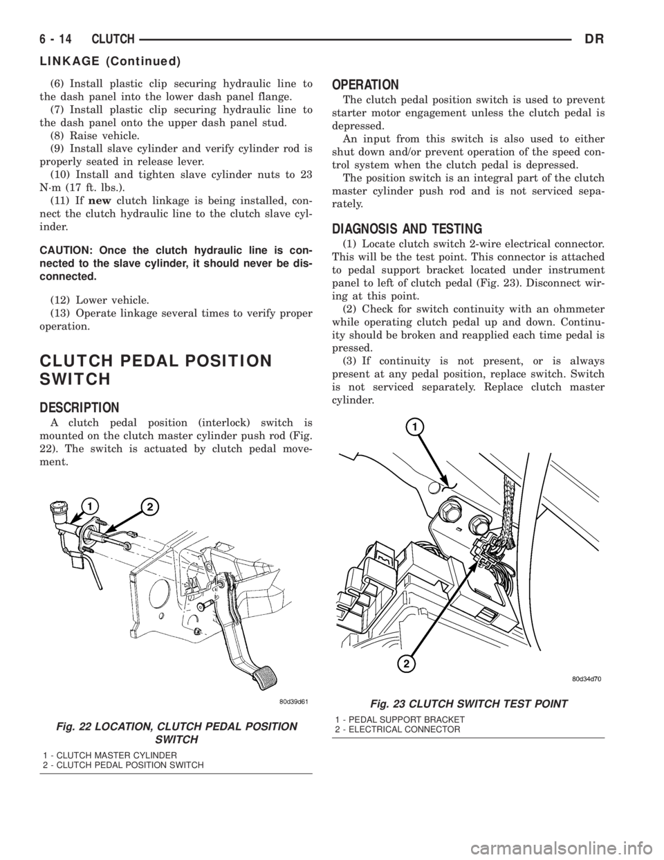
A clutch pedal position (interlock) switch is
mounted on the clutch master cylinder push rod (Fig.
22). The switch is actuated by clutch pedal move-
ment.
OPERATION
The clutch pedal position switch is used to prevent
starter motor engagement unless the clutch pedal is
depressed.
An input from this switch is also used to either
shut down and/or prevent operation of the speed con-
trol system when the clutch pedal is depressed.
The position switch is an integral part of the clutch
master cylinder push rod and is not serviced sepa-
rately.
DIAGNOSIS AND TESTING
(1) Locate clutch switch 2-wire electrical connector.
This will be the test point. This connector is attached
to pedal support bracket located under instrument
panel to left of clutch pedal (Fig. 23). Disconnect wir-
ing at this point.
(2) Check for switch continuity with an ohmmeter
while operating clutch pedal up and down. Continu-
ity should be broken and reapplied each time pedal is
pressed.
(3) If continuity is not present, or is always
present at any pedal position, replace switch. Switch
is not serviced separately. Replace clutch master
cylinder.
Fig. 22 LOCATION, CLUTCH PEDAL POSITION
SWITCH
1 - CLUTCH MASTER CYLINDER
2 - CLUTCH PEDAL POSITION SWITCH
Fig. 23 CLUTCH SWITCH TEST POINT
1 - PEDAL SUPPORT BRACKET
2 - ELECTRICAL CONNECTOR
6 - 14 CLUTCHDR
LINKAGE (Continued)
Page 294 of 2895

WARNING: DO NOT REMOVE CYLINDER BLOCK
DRAIN PLUGS OR LOOSEN RADIATOR DRAIN-
COCK WITH SYSTEM HOT AND UNDER PRESSURE.
SERIOUS BURNS FROM COOLANT CAN OCCUR.
Drain sufficient coolant to allow thermostat
removal. (Refer to 7 - COOLING/ENGINE/ENGINE
COOLANT THERMOSTAT - REMOVAL). Remove
accessory drive belt (Refer to 7 - COOLING/ACCES-
SORY DRIVE/DRIVE BELTS - REMOVAL).
Add coolant to radiator to bring level to within 6.3
mm (1/4 in) of the top of the thermostat housing.CAUTION: Avoid overheating. Do not operate
engine for an excessive period of time. Open drain-
cock immediately after test to eliminate boil over.
Start engine and accelerate rapidly three times, to
approximately 3000 rpm while observing coolant. If
internal engine combustion gases are leaking into
cooling system, bubbles will appear in coolant. If bub-
bles do not appear, internal combustion gas leakage
is not present.
DIAGNOSIS AND TESTING - COOLING SYSTEM
DIESEL ENGINE
COOLING SYSTEM DIAGNOSISÐDIESEL ENGINE
CONDITION POSSIBLE CAUSES CORRECTION
TEMPERATURE GAUGE READS
LOWNOTE:
Information on dash cluster is
displayed based on broadcast data
from ECM. DTC will be set for
engine sensor circuit concern.1. Vehicle is equipped with a heavy
duty cooling system.1. None. System operating normally.
2. Thermostat stuck open 2. Inspect and test thermostat.
3. Coolant level low. 3. Fill cooling system. (Refer to 7 -
COOLING - STANDARD
PROCEDURE)
4. Temperature gauge not
functioning correctly.4. Check cluster (Refer to 8 -
ELECTRICAL/INSTRUMENT
CLUSTER - DIAGNOSIS AND
TESTING)
DRCOOLING 7 - 7
COOLING (Continued)
Page 295 of 2895

CONDITION POSSIBLE CAUSES CORRECTION
TEMPERATURE GAUGE READS
HIGH. COOLANT MAY OR MAY
NOT BE LEAKING FROM
SYSTEMNOTE:
Information on dash cluster is
displayed based on broadcast data
from ECM. DTC will be set for
engine sensor circuit concern.1. Vehicle overloaded, high ambient
(outside) temperatures with A/C
turned on, stop and go driving or
prolonged operation at idle speeds.1. Temporary condition, repair not
required. Notify customer of vehicle
operation instructions located in
Owners Manual.
2. Temperature gauge not
functioning correctly.2. Check cluster (Refer to 8 -
ELECTRICAL/INSTRUMENT
CLUSTER - DIAGNOSIS AND
TESTING)
3. Air trapped in cooling system 3. Drain cooling system (Refer to 7 -
COOLING - STANDARD
PROCEDURE) and refill (Refer to 7
- COOLING - STANDARD
PROCEDURE)
4. Radiator cap faulty. 4. Replace radiator cap.
5. Plugged A/C or radiator cooling
fins.5. Clean all debris away from A/C
and radiator cooling fins.
6. Coolant mixture incorrect. 6. Drain cooling system (Refer to 7 -
COOLING - STANDARD
PROCEDURE) refill with correct
mixture (Refer to 7 - COOLING -
STANDARD PROCEDURE).
7. Thermostat stuck shut. 7. Inspect and test thermostat.
Replace thermostat if necessary.
8. Bug screen or winter front being
used.8. Remove bug screen or winter
front.
9. Electronically controlled viscous
fan drive not operating properly.9. Check viscous fan (Refer to 7 -
COOLING/ENGINE/FAN DRIVE
VISCOUS CLUTCH - DIAGNOSIS
AND TESTING)
10. Cylinder head gasket leaking. 10. Check for leaking head gaskets
(Refer to 7 - COOLING -
DIAGNOSIS AND TESTING).
11. Heater core leaking. 11. Replace heater core.
12. Cooling system hoses leaking. 12. Tighten clamps or Replace
hoses.
13. Brakes dragging. 13. Check brakes. (Refer to 5 -
BRAKES/HYDRAULIC/
MECHANICAL - DIAGNOSIS AND
TESTING)
14. Accessory drive belt. 14. Inspect. Replace as necessary.
15. Water Pump. 15. Inspect and replace as
necessary.
7 - 8 COOLINGDR
COOLING (Continued)
Page 296 of 2895

CONDITION POSSIBLE CAUSES CORRECTION
TEMPERATURE GAUGE READING
INCONSISTENT (ERRATIC,
CYCLES OR FLUCTUATES)NOTE:
Information on dash cluster is
displayed based on broadcast data
from ECM. DTC will be set for
engine sensor circuit concern.1. Heavy duty cooling system,
extreme cold ambient (outside)
temperature or heater blower motor
in high position.1. None. System operating normally.
2. Temperature gauge or sensor
defective.2. Check cluster or engine coolant
temp sensor (Refer to 8 -
ELECTRICAL/INSTRUMENT
CLUSTER - DIAGNOSIS AND
TESTING)
3. Temporary heavy usage or load. 3. None. Normal condition.
4. Air trapped in cooling system. 4. Fill cooling system (Refer to 7 -
COOLING - STANDARD
PROCEDURE).
5. Water pump 5. Replace water pump.
6. Air leak on suction side of water
pump.6. Check for leak. (Refer to 7 -
COOLING - DIAGNOSIS AND
TESTING)
RADIATOR CAP LEAKING STEAM
AND /OR COOLANT INTO
RESERVOIR BOTTLE.
(TEMPERATURE GAUGE MAY
READ HIGH)1. Radiator cap defective. 1. Replace radiator cap.
2. Radiator neck surface damaged. 2. Replace radiator.
HOSE OR HOSES COLLAPSE
WHEN ENGINE IS COOLING.1. Vacuum created in cooling
system on engine cool-down is not
being relieved through coolant
reservoir/overflow system.1. Replace radiator cap, check vent
hose between radiator and reservoir
bottle for blockage also check
reservoir bottle vent for blockage.
NOISY FAN 1. Fan blade(s) loose, damaged. 1. Replace fan blade assembly.
2. Electronically controlled viscous
fan drive.2. None. Normal condition.
3. Fan blades striking surrounding
objects.3. Locate contact point and repair
as necessary.
4. Electronically controlled viscous
fan drive bearing.4. Check viscous fan (Refer to 7 -
COOLING/ENGINE/FAN DRIVE
VISCOUS CLUTCH - DIAGNOSIS
AND TESTING)
5. Electronically controlled viscous
fan stuck on5. Check viscous fan (Refer to 7 -
COOLING/ENGINE/FAN DRIVE
VISCOUS CLUTCH - DIAGNOSIS
AND TESTING)
6. Obstructed air flow through
radiator.6. Remove obstruction.
DRCOOLING 7 - 9
COOLING (Continued)
Page 297 of 2895

CONDITION POSSIBLE CAUSES CORRECTION
INADEQUATE AIR CONDITIONER
PERFORMANCE (COOLING
SYSTEM SUSPECTED)1. Radiator and/or A/C condenser
air flow obstructed.1. Remove obstruction and/or clean.
2. Electronically controlled viscous
fan drive not working.2. Check fan drive. (Refer to 7 -
COOLING/ENGINE/FAN DRIVE
VISCOUS CLUTCH - DIAGNOSIS
AND TESTING)
3. Air seals around radiator
damaged or missing.3. Inspect air seals, repair or
replace as necessary.
INADEQUATE HEATER
PERFORMANCE. GAUGE MAY OR
MAY NOT READ LOW.1. Heavy duty cooling system, and
cooler ambient temperatures.1. None. Normal condition.
2. Obstruction in heater hoses. 2. Remove hoses, remove
obstruction.
3. Electronically controlled viscous
fan stuck onCheck fan drive. (Refer to 7 -
COOLING/ENGINE/FAN DRIVE
VISCOUS CLUTCH - DIAGNOSIS
AND TESTING)
4. Water pump damaged. 4. Replace water pump.
HEAT ODOR 1. Damaged or missing drive line
heat shields.1. Repair or replace damaged or
missing heat shields.
2. Electronically controlled viscous
fan drive damaged.2. Check thermal viscous fan drive.
(Refer to 7 - COOLING/ENGINE/
FAN DRIVE VISCOUS CLUTCH -
DIAGNOSIS AND TESTING)
DIAGNOSIS AND TESTING - PRELIMINARY
CHECKS
ENGINE COOLING SYSTEM OVERHEATING
Establish what driving conditions caused the com-
plaint. Abnormal loads on the cooling system such as
the following may be the cause:
²PROLONGED IDLE
²VERY HIGH AMBIENT TEMPERATURE
²SLIGHT TAIL WIND AT IDLE
²SLOW TRAFFIC
²TRAFFIC JAMS
²HIGH SPEED OR STEEP GRADES
Driving techniques that avoid overheating are:
²Idle with A/C off when temperature gauge is at
end of normal range.
²Increasing engine speed for more air flow is rec-
ommended.
TRAILER TOWING:
Consult Trailer Towing section of owners manual.
Do not exceed limits.RECENT SERVICE OR ACCIDENT REPAIR:
Determine if any recent service has been per-
formed on vehicle that may effect the cooling system.
This may be:
²Engine adjustments (incorrect timing)
²Slipping engine accessory drive belt(s)
²Brakes (possibly dragging)
²Changed parts. Incorrect water pump or pump
rotating in wrong direction due to belt not correctly
routed
²Reconditioned radiator or cooling system refill-
ing (possibly under filled or air trapped in system).
²Service to electrically controlled viscous fan
clutch
NOTE: If investigation reveals none of the previous
items as a cause for an engine overheating com-
plaint, refer to COOLING SYSTEM DIAGNOSIS
CHART BELOW.
These charts are to be used as a quick-reference
only. Refer to COOLING SYSTEM DIAGNOSIS
CHART
7 - 10 COOLINGDR
COOLING (Continued)
Page 298 of 2895

COOLING SYSTEM DIAGNOSIS CHART
CONDITION POSSIBLE CAUSES CORRECTION
TEMPERATURE GAUGE
READS LOW1. Has a Diagnostic Trouble
Code (DTC) been set indicating
a stuck open thermostat?1. (Refer to 25 - EMISSIONS CONTROL -
DESCRIPTION) for On-Board Diagnostics
and DTC information. Replace thermostat
if necessary.
2. Is the temperature sending
unit connected?2. Check the temperature sensor
connector. (Refer to 8 - ELECTRICAL/
INSTRUMENT CLUSTER - SCHEMATIC -
ELECTRICAL) Repair connector if
necessary.
3. Is the temperature gauge
operating OK?3. Check gauge operation. (Refer to 8 -
ELECTRICAL/INSTRUMENT CLUSTER/
ENGINE TEMPERATURE GAUGE -
DESCRIPTION). Repair as necessary.
4. Coolant level low in cold
ambient temperatures
accompanied with poor heater
performance.4. Check coolant level in the coolant
reserve/overflow tank or degas bottle and
the radiator. Inspect system for leaks.
Repair leaks as necessary. Refer to the
Coolant section of the manual text for
WARNINGS and CAUTIONS associated
with removing the radiator cap.
5. Improper operation of internal
heater doors or heater controls.5. Inspect heater and repair as necessary.
(Refer to 24 - HEATING & AIR
CONDITIONING - DIAGNOSIS AND
TESTING) for procedures.
DRCOOLING 7 - 11
COOLING (Continued)