2003 DODGE RAM electrical
[x] Cancel search: electricalPage 248 of 2895
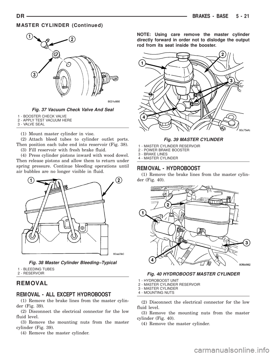
(1) Mount master cylinder in vise.
(2) Attach bleed tubes to cylinder outlet ports.
Then position each tube end into reservoir (Fig. 38).
(3) Fill reservoir with fresh brake fluid.
(4) Press cylinder pistons inward with wood dowel.
Then release pistons and allow them to return under
spring pressure. Continue bleeding operations until
air bubbles are no longer visible in fluid.
REMOVAL
REMOVAL - ALL EXCEPT HYDROBOOST
(1) Remove the brake lines from the master cylin-
der (Fig. 39).
(2) Disconnect the electrical connector for the low
fluid level.
(3) Remove the mounting nuts from the master
cylinder (Fig. 39).
(4) Remove the master cylinder.NOTE: Using care remove the master cylinder
directly forward in order not to dislodge the output
rod from its seat inside the booster.
REMOVAL - HYDROBOOST
(1) Remove the brake lines from the master cylin-
der (Fig. 40).
(2) Disconnect the electrical connector for the low
fluid level.
(3) Remove the mounting nuts from the master
cylinder (Fig. 40).
(4) Remove the master cylinder.
Fig. 37 Vacuum Check Valve And Seal
1 - BOOSTER CHECK VALVE
2 - APPLY TEST VACUUM HERE
3 - VALVE SEAL
Fig. 38 Master Cylinder Bleeding±Typical
1 - BLEEDING TUBES
2 - RESERVOIR
Fig. 39 MASTER CYLINDER
1 - MASTER CYLINDER RESERVOIR
2 - POWER BRAKE BOOSTER
3 - BRAKE LINES
4 - MASTER CYLINDER
Fig. 40 HYDROBOOST MASTER CYLINDER
1 - HYDROBOOST UNIT
2 - MASTER CYLINDER RESERVOIR
3 - MASTER CYLINDER
4 - MOUNTING NUTS
DRBRAKES - BASE 5 - 21
MASTER CYLINDER (Continued)
Page 249 of 2895
NOTE: Using care remove the master cylinder
directly forward in order not to dislodge the output
rod from its seat inside the booster.
INSTALLATION
INSTALLATION - ALL EXCEPT HYDROBOOST
NOTE: If master cylinder is replaced bleed cylinder
before installation.
NOTE: Make sure the output rod of the brake
booster is in position before mounting of the mas-
ter cylinder ªThis position will enable the output
rod to enter inside of the master cylinder plunger
sleeve during installationº. Proper position is
obtained when the output rod is centered perpen-
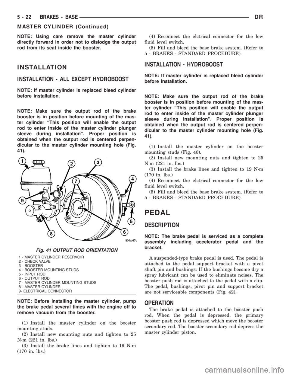
dicular to the master cylinder mounting hole (Fig.
41).
NOTE: Before installing the master cylinder, pump
the brake pedal several times with the engine off to
remove vacuum from the booster.
(1) Install the master cylinder on the booster
mounting studs.
(2) Install new mounting nuts and tighten to 25
N´m (221 in. lbs.)
(3) Install the brake lines and tighten to 19 N´m
(170 in. lbs.)(4) Reconnect the elctrical connector for the low
fluid level switch.
(5) Fill and bleed the base brake system. (Refer to
5 - BRAKES - STANDARD PROCEDURE).
INSTALLATION - HYDROBOOST
NOTE: If master cylinder is replaced bleed cylinder
before installation.
NOTE: Make sure the output rod of the brake
booster is in position before mounting of the mas-
ter cylinder ªThis position will enable the output
rod to enter inside of the master cylinder plunger
sleeve during installationº. Proper position is
obtained when the output rod is centered perpen-
dicular to the master cylinder mounting hole (Fig.
41).
(1) Install the master cylinder on the booster
mounting studs (Fig. 40).
(2) Install new mounting nuts and tighten to 25
N´m (221 in. lbs.)
(3) Install the brake lines and tighten to 19 N´m
(170 in. lbs.)
(4) Reconnect the elctrical connector for the low
fluid level switch.
(5) Fill and bleed the base brake system. (Refer to
5 - BRAKES - STANDARD PROCEDURE).
PEDAL
DESCRIPTION
NOTE: The brake pedal is serviced as a complete
assembly including accelerator pedal and the
bracket.
A suspended-type brake pedal is used. The pedal is
attached to the pedal support bracket with a pivot
shaft pin and bushings. If the bushings become dry a
spray lubricant can be used to eliminate noises. The
booster push rod is attached to the pedal with a clip.
The pedal, bushings, pivot pin and support bracket
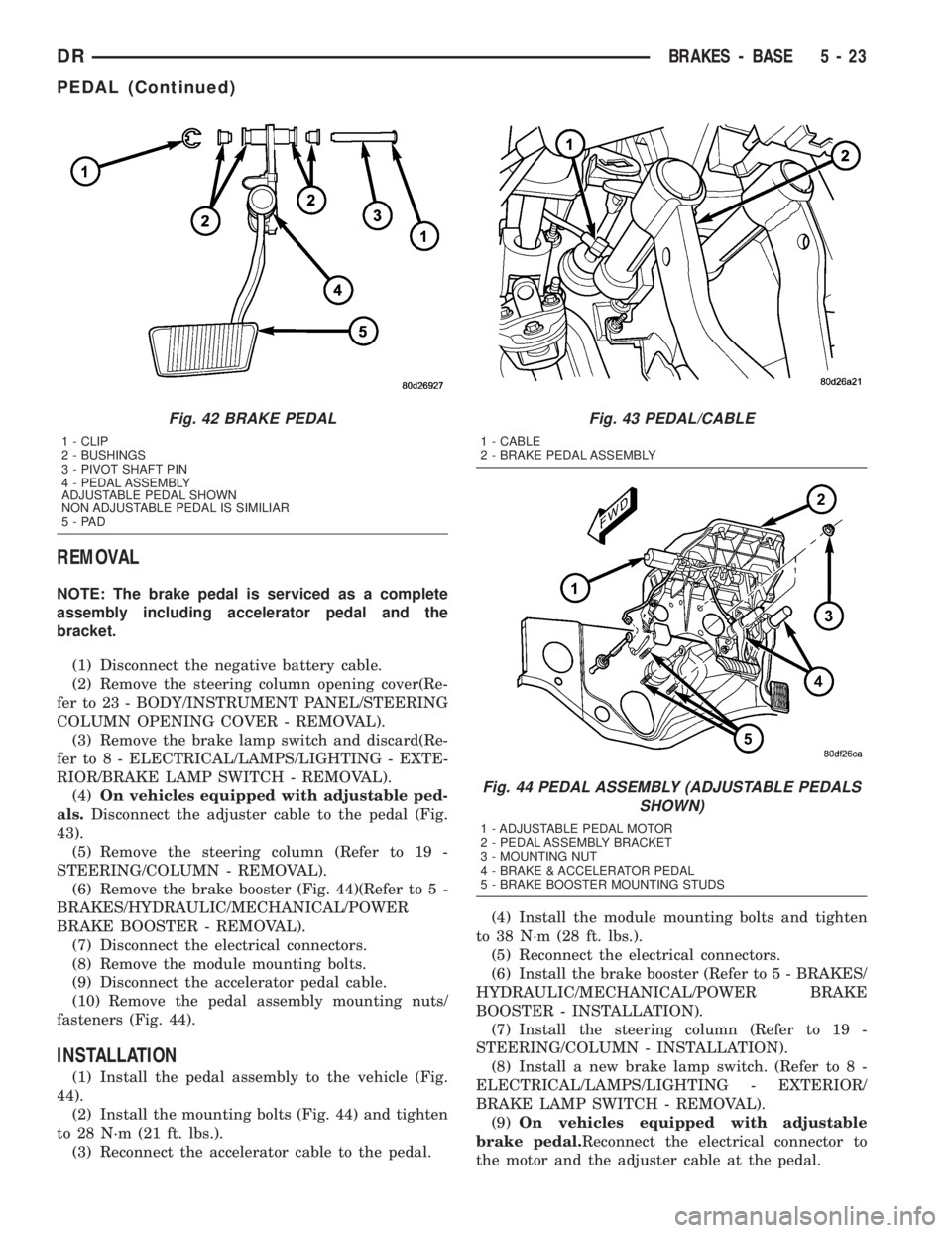
are not serviceable components (Fig. 42).
OPERATION
The brake pedal is attached to the booster push
rod. When the pedal is depressed, the primary
booster push rod is depressed which move the booster
secondary rod. The booster secondary rod depress the
master cylinder piston.
Fig. 41 OUTPUT ROD ORIENTATION
1 - MASTER CYLINDER RESERVOIR
2 - CHECK VALVE
3 - BOOSTER
4 - BOOSTER MOUNTING STUDS
5 - INPUT ROD
6 - OUTPUT ROD
7 - MASTER CYLINDER MOUNTING STUDS
8 - MASTER CYLINDER
9- ELECTRICAL CONNECTOR
5 - 22 BRAKES - BASEDR
MASTER CYLINDER (Continued)
Page 250 of 2895
REMOVAL
NOTE: The brake pedal is serviced as a complete
assembly including accelerator pedal and the
bracket.
(1) Disconnect the negative battery cable.
(2) Remove the steering column opening cover(Re-
fer to 23 - BODY/INSTRUMENT PANEL/STEERING
COLUMN OPENING COVER - REMOVAL).
(3) Remove the brake lamp switch and discard(Re-
fer to 8 - ELECTRICAL/LAMPS/LIGHTING - EXTE-
RIOR/BRAKE LAMP SWITCH - REMOVAL).
(4)On vehicles equipped with adjustable ped-
als.Disconnect the adjuster cable to the pedal (Fig.
43).
(5) Remove the steering column (Refer to 19 -
STEERING/COLUMN - REMOVAL).
(6) Remove the brake booster (Fig. 44)(Refer to 5 -
BRAKES/HYDRAULIC/MECHANICAL/POWER
BRAKE BOOSTER - REMOVAL).
(7) Disconnect the electrical connectors.
(8) Remove the module mounting bolts.
(9) Disconnect the accelerator pedal cable.
(10) Remove the pedal assembly mounting nuts/
fasteners (Fig. 44).
INSTALLATION
(1) Install the pedal assembly to the vehicle (Fig.
44).
(2) Install the mounting bolts (Fig. 44) and tighten
to 28 N´m (21 ft. lbs.).
(3) Reconnect the accelerator cable to the pedal.(4) Install the module mounting bolts and tighten
to 38 N´m (28 ft. lbs.).
(5) Reconnect the electrical connectors.
(6) Install the brake booster (Refer to 5 - BRAKES/
HYDRAULIC/MECHANICAL/POWER BRAKE
BOOSTER - INSTALLATION).
(7) Install the steering column (Refer to 19 -
STEERING/COLUMN - INSTALLATION).
(8) Install a new brake lamp switch. (Refer to 8 -
ELECTRICAL/LAMPS/LIGHTING - EXTERIOR/
BRAKE LAMP SWITCH - REMOVAL).
(9)On vehicles equipped with adjustable
brake pedal.Reconnect the electrical connector to
the motor and the adjuster cable at the pedal.
Fig. 42 BRAKE PEDAL
1 - CLIP
2 - BUSHINGS
3 - PIVOT SHAFT PIN
4 - PEDAL ASSEMBLY
ADJUSTABLE PEDAL SHOWN
NON ADJUSTABLE PEDAL IS SIMILIAR
5-PAD
Fig. 43 PEDAL/CABLE
1 - CABLE
2 - BRAKE PEDAL ASSEMBLY
Fig. 44 PEDAL ASSEMBLY (ADJUSTABLE PEDALS
SHOWN)
1 - ADJUSTABLE PEDAL MOTOR
2 - PEDAL ASSEMBLY BRACKET
3 - MOUNTING NUT
4 - BRAKE & ACCELERATOR PEDAL
5 - BRAKE BOOSTER MOUNTING STUDS
DRBRAKES - BASE 5 - 23
PEDAL (Continued)
Page 251 of 2895
(10) Install the steering column opening cover
(Refer to 23 - BODY/INSTRUMENT PANEL/STEER-
ING COLUMN OPENING COVER - INSTALLA-
TION).
(11) Reconnect the negative battery cable.
ADJUSTABLE PEDAL MOTOR
DESCRIPTION
The Adjustable Pedals System (APS) is designed to
enable the fore and aft repositioning of the brake and
accelerator pedals. This results in improved ergonom-
ics in relation to the steering wheel for taller and
shorter drivers. Being able to adjust the pedal posi-
tions also allows the driver to set steering wheel tilt
and seat position to the most comfortable position.
The position of the brake and accelerator pedals can
be adjusted without compromising safety or comfort
in actuating the pedals.
Change of pedal position is accomplished by means
of a motor driven screw. Operating the adjustable
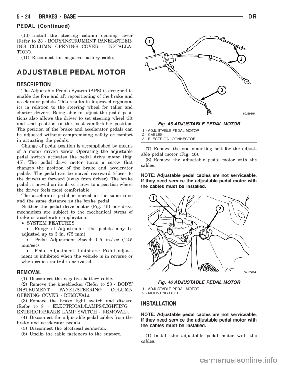
pedal switch activates the pedal drive motor (Fig.
45). The pedal drive motor turns a screw that
changes the position of the brake and accelerator
pedals. The pedal can be moved rearward (closer to
the driver) or forward (away from driver). The brake
pedal is moved on its drive screw to a position where
the driver feels most comfortable.
The accelerator pedal is moved at the same time
and the same distance as the brake pedal.
Neither the pedal drive motor (Fig. 45) nor drive
mechanism are subject to the mechanical stress of
brake or accelerator application.
²SYSTEM FEATURES:
²Range of Adjustment: The pedals may be
adjusted up to 3 in. (75 mm)
²Pedal Adjustment Speed: 0.5 in./sec (12.5
mm/sec)
²Pedal Adjustment Inhibitors: Pedal adjust-
ment is inhibited when the vehicle is in reverse or
when cruise control is activated.
REMOVAL
(1) Disconnect the negative battery cable.
(2) Remove the kneeblocker (Refer to 23 - BODY/
INSTRUMENT PANEL/STEERING COLUMN
OPENING COVER - REMOVAL).
(3) Remove the brake light switch and discard
(Refer to 8 - ELECTRICAL/LAMPS/LIGHTING -
EXTERIOR/BRAKE LAMP SWITCH - REMOVAL).
(4) Disconnect the adjustable pedal cables from the
brake and accelerator pedals.
(5) Disconnect the electrical connector.
(6) Unclip the cable fasteners to the support.(7) Remove the one mounting bolt for the adjust-
able pedal motor (Fig. 46).
(8) Remove the adjustable pedal motor with the
cables.
NOTE: Adjustable pedal cables are not serviceable.
If they need service the adjustable pedal motor with
the cables must be installed.
INSTALLATION
NOTE: Adjustable pedal cables are not serviceable.
If they need service the adjustable pedal motor with
the cables must be installed.
(1) Install the adjustable pedal motor with the
cables.
Fig. 45 ADJUSTABLE PEDAL MOTOR
1 - ADJUSTABLE PEDAL MOTOR
2 - CABLES
3 - ELECTRICAL CONNECTOR
Fig. 46 ADJUSTABLE PEDAL MOTOR
1 - ADJUSTABLE PEDAL MOTOR
2 - MOUNTING BOLT
5 - 24 BRAKES - BASEDR
PEDAL (Continued)
Page 252 of 2895
(2) Install the one mounting bolt for the adjustable
pedal motor (Fig. 46).
(3) Clip the cable fasteners to the support.
(4) Reconnect the electrical connector.
(5) Reconnect the adjustable pedal cables to the
brake and accelerator pedals.
(6) Install the new brake light switch (Refer to 8 -
ELECTRICAL/LAMPS/LIGHTING - EXTERIOR/
BRAKE LAMP SWITCH - REMOVAL).
(7) Install the kneeblocker (Refer to 23 - BODY/IN-
STRUMENT PANEL/STEERING COLUMN OPEN-
ING COVER - INSTALLATION).
(8) Reconnect the negative battery cable.
(9) Check for proper operation of the pedals.
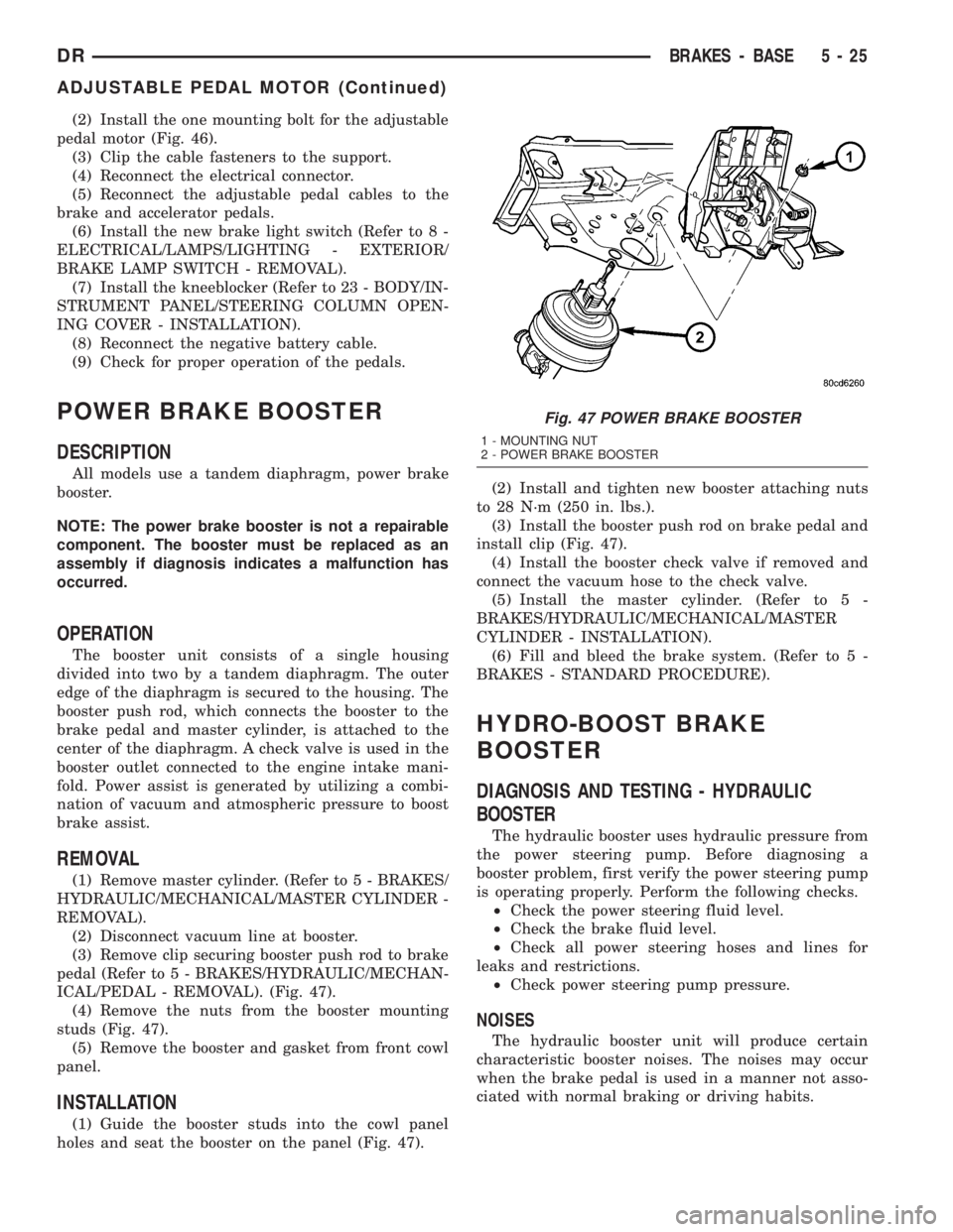
POWER BRAKE BOOSTER
DESCRIPTION
All models use a tandem diaphragm, power brake
booster.
NOTE: The power brake booster is not a repairable
component. The booster must be replaced as an
assembly if diagnosis indicates a malfunction has
occurred.
OPERATION
The booster unit consists of a single housing
divided into two by a tandem diaphragm. The outer
edge of the diaphragm is secured to the housing. The
booster push rod, which connects the booster to the
brake pedal and master cylinder, is attached to the
center of the diaphragm. A check valve is used in the
booster outlet connected to the engine intake mani-
fold. Power assist is generated by utilizing a combi-
nation of vacuum and atmospheric pressure to boost
brake assist.
REMOVAL
(1) Remove master cylinder. (Refer to 5 - BRAKES/
HYDRAULIC/MECHANICAL/MASTER CYLINDER -
REMOVAL).
(2) Disconnect vacuum line at booster.
(3) Remove clip securing booster push rod to brake
pedal (Refer to 5 - BRAKES/HYDRAULIC/MECHAN-
ICAL/PEDAL - REMOVAL). (Fig. 47).
(4) Remove the nuts from the booster mounting
studs (Fig. 47).
(5) Remove the booster and gasket from front cowl
panel.
INSTALLATION
(1) Guide the booster studs into the cowl panel
holes and seat the booster on the panel (Fig. 47).(2) Install and tighten new booster attaching nuts
to 28 N´m (250 in. lbs.).
(3) Install the booster push rod on brake pedal and
install clip (Fig. 47).
(4) Install the booster check valve if removed and
connect the vacuum hose to the check valve.
(5) Install the master cylinder. (Refer to 5 -
BRAKES/HYDRAULIC/MECHANICAL/MASTER
CYLINDER - INSTALLATION).
(6) Fill and bleed the brake system. (Refer to 5 -
BRAKES - STANDARD PROCEDURE).
HYDRO-BOOST BRAKE
BOOSTER
DIAGNOSIS AND TESTING - HYDRAULIC
BOOSTER
The hydraulic booster uses hydraulic pressure from
the power steering pump. Before diagnosing a
booster problem, first verify the power steering pump
is operating properly. Perform the following checks.
²Check the power steering fluid level.
²Check the brake fluid level.
²Check all power steering hoses and lines for
leaks and restrictions.
²Check power steering pump pressure.
NOISES
The hydraulic booster unit will produce certain
characteristic booster noises. The noises may occur
when the brake pedal is used in a manner not asso-
ciated with normal braking or driving habits.
Fig. 47 POWER BRAKE BOOSTER
1 - MOUNTING NUT
2 - POWER BRAKE BOOSTER
DRBRAKES - BASE 5 - 25
ADJUSTABLE PEDAL MOTOR (Continued)
Page 266 of 2895

BRAKES - ABS
TABLE OF CONTENTS
page page
BRAKES - ABS
DESCRIPTION.........................39
OPERATION...........................39
STANDARD PROCEDURE - ABS BRAKE
BLEEDING...........................40
SPECIFICATIONS
TORQUE CHART......................40
FRONT WHEEL SPEED SENSOR
DESCRIPTION.........................41
OPERATION...........................41
REMOVAL.............................41
INSTALLATION.........................42
REAR WHEEL SPEED SENSOR
DIAGNOSIS AND TESTING - REAR WHEEL
ANTILOCK...........................42
REMOVAL.............................42
INSTALLATION.........................43
TONE WHEEL
DIAGNOSIS AND TESTING - REAR WHEEL
SPEED SENSOR......................43HYDRAULIC/MECHANICAL
DESCRIPTION - ELECTRONIC VARIABLE
BRAKE PROPORTIONING...............43
OPERATION - ELECTRONIC VARIABLE
BRAKE PROPORTIONING...............43
HCU (HYDRAULIC CONTROL UNIT)
DESCRIPTION.........................43
OPERATION...........................43
REMOVAL.............................44
INSTALLATION.........................44
R WA L VA LV E
DESCRIPTION.........................44
OPERATION...........................44
REMOVAL.............................45
INSTALLATION.........................45
BRAKES - ABS
DESCRIPTION
The antilock brake system (ABS) is an electroni-
cally operated, three channel brake control system.
The vehicle has Electronic Variable Brake Propor-
tioning (EVBP) designed into the system which elim-
inates the combination/proportioning valve.
The system is designed to prevent wheel lockup
and maintain steering control during braking. Pre-
venting lockup is accomplished by modulating fluid
pressure to the wheel brake units.
The hydraulic system is a three channel design.
The front wheel brakes are controlled individually
and the rear wheel brakes in tandem. The ABS elec-
trical system is separate from other electrical circuits
in the vehicle. A specially programmed controller
antilock brake unit operates the system components.
ABS system major components include:
²Controller Antilock Brakes (CAB)
²Hydraulic Control Unit (HCU)
²Wheel Speed Sensors (WSS)
²ABS Warning Light
OPERATION
Battery voltage is supplied to the CAB. The CAB
performs a system initialization procedure at start
up. A check of the ABS motor is performed at 15
miles per hour. Initialization consists of a static and
dynamic self check of system electrical components.
The static and dynamic checks occurs at ignition
start up. During the dynamic check, the CAB briefly
cycles solenoids to verify operation. An audible noise
may be heard during this self check. This noise
should be considered normal. The ABS motor and
pump are then checked at a speed of 15 mile per
hour.
If an ABS component exhibits a fault during ini-
tialization, the CAB illuminates the amber warning
light and registers a fault code in the microprocessor
memory.
The CAB monitors wheel speed sensor inputs con-
tinuously while the vehicle is in motion. However,
the CAB will not activate any ABS components as
long as sensor inputs indicate normal braking.
During normal braking, the master cylinder, power
booster and wheel brake units all function as they
would in a vehicle without ABS. The HCU compo-
nents are not activated.
DRBRAKES - ABS 5 - 39
Page 267 of 2895

The purpose of the antilock system is to prevent
wheel lockup. Preventing lockup helps maintain vehi-
cle braking action and steering control.
The antilock CAB activates the system whenever
sensor signals indicate periods of wheel slip.
The antilock system prevents lockup during a
wheel slip condition by modulating fluid apply pres-
sure to the wheel brake units.
Brake fluid apply pressure is modulated according
to wheel speed, degree of slip and rate of decelera-
tion. Sensors at each front wheel convert wheel speed
into electrical signals. These signals are transmitted
to the CAB for processing and determination of
wheel slip and deceleration rate.
The ABS system has three fluid pressure control
channels. The front brakes are controlled separately
and the rear brakes in tandem. A speed sensor input
signal indicating a wheel slip condition activates the
CAB antilock program.
There are Two solenoid valves (Isolation and Dump
valve) which are used in each antilock control chan-
nel. The valves are all located within the HCU valve
body and work in pairs to either increase, hold, or
decrease apply pressure as needed in the individual
control channels.
During an ABS stop the ISO valve is energized
which acts to prevent further pressure build-up tothe calipers. Then the Dump valve dumps off pres-
sure until the wheel unlocks. This will continue until
the wheels quit slipping altogether.
STANDARD PROCEDURE - ABS BRAKE
BLEEDING
ABS system bleeding requires conventional bleed-
ing methods plus use of the DRB scan tool. The pro-
cedure involves performing a base brake bleeding,
followed by use of the scan tool to cycle and bleed the
HCU pump and solenoids. A second base brake bleed-
ing procedure is then required to remove any air
remaining in the system.
(1) Perform base brake bleeding,(Refer to 5 -
BRAKES - STANDARD PROCEDURE) OR (Refer to
5 - BRAKES - STANDARD PROCEDURE).
(2) Connect scan tool to the Data Link Connector.
(3) Select ANTILOCK BRAKES, followed by MIS-
CELLANEOUS, then ABS BRAKES. Follow the
instructions displayed. When scan tool displays TEST
COMPLETE, disconnect scan tool and proceed.
(4) Perform base brake bleeding a second time,(Re-
fer to 5 - BRAKES - STANDARD PROCEDURE) OR
(Refer to 5 - BRAKES - STANDARD PROCEDURE).
(5) Top off master cylinder fluid level and verify
proper brake operation before moving vehicle.
SPECIFICATIONS
TORQUE CHART
TORQUE SPECIFICATIONS
DESCRIPTION N´m Ft. Lbs. In. Lbs.
ABS Assembly
Mounting Bolts15 11 Ð
ABS Assembly
CAB Screws3.5 Ð 31
ABS Assembly
Brake Line Fittings19 Ð 170
Wheel Speed Sensors
Front Sensor Bolt21 Ð 190
Wheel Speed Sensors
Bracket To Knuckle6.7 Ð 60
Wheel Speed Sensors
Rear Sensor Stud22.5 Ð 200
Controller
Mounting Screws6Ð53
RWAL Module
Mounting Bolts15 11 Ð
5 - 40 BRAKES - ABSDR
BRAKES - ABS (Continued)
Page 269 of 2895

(3) Remove the wheel speed sensor from the hub.
(4) Remove the wiring from the clips and discon-
nect the electrical connector.
INSTALLATION
(1) Install the wiring to the clips and Reconnect
the electrical connector.
(2) Install the wheel speed sensor to the hub.
(3) Install the wheel speed sensor mounting bolt to
the hub. Tighten the bolt to 21 N´m (190 in. lbs.).
(4) Install the front rotor and brake caliper assem-
bly (Refer to 5 - BRAKES/HYDRAULIC/MECHANI-
CAL/ROTORS - INSTALLATION).
REAR WHEEL SPEED SENSOR
DIAGNOSIS AND TESTING - REAR WHEEL
ANTILOCK
Diagnosis of base brake conditions which are
mechanical in nature should be performed first. This
includes brake noise, lack of power assist, parking
brake, or vehicle vibration during normal braking.
The RWAL brake system performs several self-
tests every time the ignition switch is turned on and
the vehicle is driven. The CAB monitors the system
inputs and outputs circuits to verify the system is
operating properly. If the CAB senses a malfunction
in the system it will set a DTC into memory and trig-
ger the warning lamp.
NOTE: The MDS or DRB III scan tool is used to
diagnose the RWAL system. For test procedures
refer to the Chassis Diagnostic Manual.
REMOVAL
(1) Raise the vehicle on a hoist.
(2) Remove the brake line mounting nut and
remove the brake line from the sensor stud.
(3) Remove the mounting stud from the sensor and
shield (Fig. 4).
(4) Remove the sensor and shield from the differ-
ential housing.
(5) Disconnect the sensor wire harness and remove
the sensor.
Fig. 2 Data Link Connector - Typical
1 - 16±WAY DATA LINK CONNECTOR
Fig. 3 WHEEL SPEED SENSOR
1 - WHEEL SPEED SENSOR MOUNTING BOLT
2 - WHEEL SPEED SENSOR
3 - HUB/BEARING
Fig. 4 REAR WHEEL SPEED SENSOR
1 - WHEEL SPEED SENSOR
2 - MOUNTING BOLT
3 - AXLE HOUSING
5 - 42 BRAKES - ABSDR
FRONT WHEEL SPEED SENSOR (Continued)