2003 DODGE RAM turn signal bulb
[x] Cancel search: turn signal bulbPage 544 of 2895

STANDARD PROCEDURE
SAFETY PRECAUTIONS
WARNING: EYE PROTECTION SHOULD BE USED
WHEN SERVICING GLASS COMPONENTS. PER-
SONAL INJURY CAN RESULT.
CAUTION: Do not touch the glass of halogen bulbs
with fingers or other possibly oily surface, reduced
bulb life will result.Do not use bulbs with higher
candle power than indicated in the Bulb Application
table . Damage to lamp and/or Daytime Running
Lamp Module can result.Do not use fuses, circuit
breakers or relays having greater amperage value
than indicated on the fuse panel or in the Owners
Manual.
When it is necessary to remove components to ser-
vice another, it should not be necessary to apply
excessive force or bend a component to remove it.
Before damaging a trim component, verify hidden
fasteners or captured edges are not holding the com-
ponent in place.
SPECIFICATIONS
EXTERIOR LAMPS
CAUTION: Do not use bulbs that have a higher can-
dle power than the bulb listed in the Bulb Applica-
tion Table. Damage to lamp can result. Do not touch
halogen bulbs with fingers or other oily surfaces.
Bulb life will be reduced.
The following Bulb Application Table lists the lamp
title on the left side of the column and trade number
or part number on the right.
BULB APPLICATION TABLE
LAMP BULB
Back-up 3157
Center High Mounted
Stop lamp912
Fog lamp 9006LL
Front Park/Turn Signal 4157NAK
Head lamp 9007
License Plate 7F69
Tail, Brake, Turn Signal 3157
Side Marker, Tail Gate,
Cab Clearance168
SPECIAL TOOLS - HEADLAMP ALIGNMENT
BACKUP LAMP
REMOVAL
(1) Remove and isolate the negitive battery cable.
(2) Remove the taillamp unit (Refer to 8 - ELEC-
TRICAL/LAMPS/LIGHTING - EXTERIOR/TAIL
LAMP UNIT - REMOVAL).
(3) Remove the bulb back plate from the tail lamp
unit.
(4) Separate the bulb from the socket.
INSTALLATION
(1) Install the bulb into the socket.
(2) Install the bulb back plate to the tail lamp
unit.
(3) Install the tail lamp unit (Refer to 8 - ELEC-
TRICAL/LAMPS/LIGHTING - EXTERIOR/TAIL
LAMP UNIT - INSTALLATION).
(4) Reconnect the negative battery cable.
BACKUP LAMP SWITCH
DESCRIPTION
Vehicles equipped with a manual transmission
have a normally open, spring-loaded plunger type
back-up lamp switch (Fig. 1). The backup lamp
switch is located in a threaded hole on the side of the
manual transmission housing. The backup lamp
switch has a threaded body and a hex formation near
the plunger end of the switch, and an integral con-
nector at the opposite end of the switch. When
installed, only the connector and the hex formation
are visible on the outside of the transmission hous-
ing. Vehicles with an optional electronic automatic
transmission have a Transmission Range Sensor
(TRS) that is used to perform several functions,
including that of the backup lamp switch. The TRS is
described in further detail elsewhere in this service
information. The backup lamp switch cannot be
adjusted or repaired and, if faulty or damaged, the
entire switch unit must be replaced.
Headlamp Aiming Kit C-4466±A
DRLAMPS/LIGHTING - EXTERIOR 8L - 7
LAMPS/LIGHTING - EXTERIOR (Continued)
Page 550 of 2895

(3) Resistance between terminals 85 and 86 (elec-
tromagnet) should be 75 8 ohms. If OK, go to Step
4. If not OK, replace the faulty relay.
(4) Connect a battery to terminals 85 and 86.
There should now be continuity between terminals
30 and 87, and no continuity between terminals 87A
and 30. If OK, reinstall the relay and use a DRBIIIt
scan tool to perform further testing. Refer to the
appropriate diagnostic information.
REMOVAL
WARNING: ON VEHICLES EQUIPPED WITH AIR-
BAGS, DISABLE THE SUPPLEMENTAL RESTRAINT
SYSTEM BEFORE ATTEMPTING ANY STEERING
WHEEL, STEERING COLUMN, DRIVER AIRBAG,
PASSENGER AIRBAG, SEAT BELT TENSIONER,
FRONT IMPACT SENSORS, SIDE CURTAIN AIRBAG,
OR INSTRUMENT PANEL COMPONENT DIAGNOSIS
OR SERVICE. DISCONNECT AND ISOLATE THE
BATTERY NEGATIVE (GROUND) CABLE, THEN
WAIT TWO MINUTES FOR THE SYSTEM CAPACI-
TOR TO DISCHARGE BEFORE PERFORMING FUR-
THER DIAGNOSIS OR SERVICE. THIS IS THE ONLY
SURE WAY TO DISABLE THE SUPPLEMENTAL
RESTRAINT SYSTEM. FAILURE TO TAKE THE
PROPER PRECAUTIONS COULD RESULT IN ACCI-
DENTAL AIRBAG DEPLOYMENT AND POSSIBLE
PERSONAL INJURY.
(1) Disconnect and isolate the battery negative
cable.
(2) Remove the cover for the Power Distribution
Center (PDC).
(3) Remove the front fog lamp relay by grasping it
firmly and pulling it straight out from the receptacle
in the PDC.
INSTALLATION
WARNING: ON VEHICLES EQUIPPED WITH AIR-
BAGS, DISABLE THE SUPPLEMENTAL RESTRAINT
SYSTEM BEFORE ATTEMPTING ANY STEERING
WHEEL, STEERING COLUMN, DRIVER AIRBAG,
PASSENGER AIRBAG, SEAT BELT TENSIONER,
FRONT IMPACT SENSORS, SIDE CURTAIN AIRBAG,
OR INSTRUMENT PANEL COMPONENT DIAGNOSIS
OR SERVICE. DISCONNECT AND ISOLATE THE
BATTERY NEGATIVE (GROUND) CABLE, THEN
WAIT TWO MINUTES FOR THE SYSTEM CAPACI-
TOR TO DISCHARGE BEFORE PERFORMING FUR-
THER DIAGNOSIS OR SERVICE. THIS IS THE ONLY
SURE WAY TO DISABLE THE SUPPLEMENTAL
RESTRAINT SYSTEM. FAILURE TO TAKE THE
PROPER PRECAUTIONS COULD RESULT IN ACCI-
DENTAL AIRBAG DEPLOYMENT AND POSSIBLE
PERSONAL INJURY.(1) Position the front fog lamp relay to the proper
receptacle in the Power Distribution Center (PDC).
(2) Align the front fog lamp relay terminals with
the terminal cavities in the PDC.
(3) Press firmly and evenly on the top of the front
fog lamp relay until the terminals are fully seated in
the PDC.
(4) Reconnect the battery negative cable.
HAZARD SWITCH
DESCRIPTION
The hazard switch is activated by a push button
located in the multifunction switch on the top of the
steering column between the steering wheel and
instrument cluster.
The hazard warning system allows the vehicle
operator to provide other vehicle operators in the
near proximity an optical indication that the vehicle
is disabled or an obstacle to traffic flow. The hazard
warning system has battery voltage at all times,
regardless of ignition position.
OPERATION
The instrument cluster monitors the multiplexed
multifunction switch operation. When the hazard
warning switch is activated, the instrument cluster
will send a J1850 bus message to the Front Control
Module (FCM), then activate the two turn signal indi-
cators and audible click in the instrument cluster.
The FCM will then activate the necessary relays in
the Power Distribution Center (PDC) to begin flash-
ing both the front and rear turn signal indicator
lamps.
HEADLAMP
REMOVAL
(1) Disconnect and isolate the negitive battery
cable.
(2) Remove the headlamp unit (Refer to 8 - ELEC-
TRICAL/LAMPS/LIGHTING - EXTERIOR/HEAD-
LAMP UNIT - REMOVAL).
(3) Seperate the socket from the headlamp unit.
INSTALLATION
CAUTION: Do Not Touch the bulb glass with fingers
or other oily surfaces. Reduced bulb life will result.
(1) Install the socket into the headlamp unit.
(2) Install the headlamp unit (Refer to 8 - ELEC-
TRICAL/LAMPS/LIGHTING - EXTERIOR/HEAD-
LAMP UNIT - INSTALLATION).
(3) Connect the negitive battery cable.
DRLAMPS/LIGHTING - EXTERIOR 8L - 13
FOG LAMP RELAY (Continued)
Page 552 of 2895

(4) Install the cluster bezel onto the instrument
panel (Fig. 9).
(5) Connect the battery negative cable.
HEADLAMP UNIT
REMOVAL
(1) Disconnect and isolate the battery negative
cable.
(2) Remove the push pins attaching the seal to the
fender.
(3) Remove the bolts attaching the headlamp unit
to the fender (Fig. 10).
(4) Remove the bulb sockets from the headlamp
unit
(5) Separate headlamp unit from vehicle.
INSTALLATION
CAUTION: Do not touch the bulb glass with fingers
or other oily surfaces. Reduced bulb life will result.
(1) Install the bulb sockets for the front park/turn
signal and headlamp.
(2) Position headlamp unit in inner fender panel.
(3) Install the bolts attaching headlamp unit to the
fender (Fig. 10).
(4) Align the seal and install the push pins.
(5) Connect the battery negative cable.
ADJUSTMENTS
Headlamps can be aligned using the screen method
provided in this section. Alignment Tool C-4466-A or
equivalent can also be used. Refer to instructions
provided with the tool for proper procedures.
LAMP ALIGNMENT SCREEN PREPARATION
(1) Position vehicle on a level surface perpendicu-
lar to a flat wall 7.62 meters (25 ft) away from front
of headlamp lens (Fig. 11).
(2) If necessary, tape a line on the floor 7.62
meters (25 ft) away from and parallel to the wall.
(3) Up 1.27 meters (5 feet) from the floor, tape a
line on the wall at the centerline of the vehicle. Sight
along the centerline of the vehicle (from rear of vehi-
cle forward) to verify accuracy of the line placement.
(4) Rock vehicle side-to-side three times to allow
suspension to stabilize.
(5) Jounce front suspension three times by pushing
downward on front bumper and releasing.
(6) Measure the distance from the center of head-
lamp lens to the floor. Transfer measurement to the
alignment screen (with tape). Use this line for
up/down adjustment reference.
(7) Measure distance from the centerline of the
vehicle to the center of each headlamp being aligned.
Transfer measurements to screen (with tape) to each
side of vehicle centerline. Use these lines for left/
right adjustment reference.
VEHICLE PREPARATION FOR HEADLAMP
ALIGNMENT
(1) Verify headlamp dimmer switch and high beam
indicator operation.
(2) Correct defective components that could hinder
proper headlamp alignment.
(3) Verify proper tire inflation.
(4) Clean headlamp lenses.
(5) Verify that luggage area is not heavily loaded.
(6) Fuel tank should be FULL. Add 2.94 kg (6.5
lbs.) of weight over the fuel tank for each estimated
gallon of missing fuel.
HEADLAMP ALIGNMENT
A properly aimed low beam headlamp will project
top edge of high intensity pattern on screen from 50
mm (2 in.) above to 50 mm (2 in.) below headlamp
centerline. The side-to-side outboard edge of high
intensity pattern should be from 50 mm (2 in.) left to
50 mm (2 in.) right of headlamp centerline (Fig. 11).
The preferred headlamp alignment is 1(down
for the up/down adjustment and 0 for the left/
right adjustment.The high beam pattern should be
correct when the low beams are aligned properly.
To adjust low beam headlamp, rotate alignment
screws to achieve the specified aim.
Fig. 10 HEADLAMP Ð TYPICAL
1 - SEAL
2 - PUSH PIN
3 - SCREW
4 - HEADLAMP UNIT
DRLAMPS/LIGHTING - EXTERIOR 8L - 15
HEADLAMP SWITCH (Continued)
Page 554 of 2895
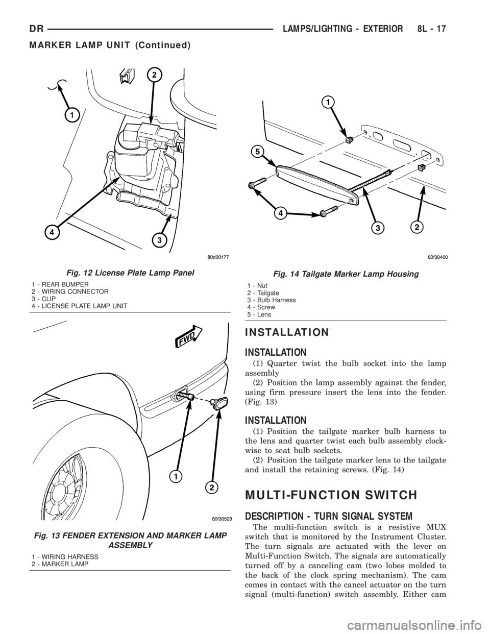
INSTALLATION
INSTALLATION
(1) Quarter twist the bulb socket into the lamp
assembly
(2) Position the lamp assembly against the fender,
using firm pressure insert the lens into the fender.
(Fig. 13)
INSTALLATION
(1) Position the tailgate marker bulb harness to
the lens and quarter twist each bulb assembly clock-
wise to seat bulb sockets.
(2) Position the tailgate marker lens to the tailgate
and install the retaining screws. (Fig. 14)
MULTI-FUNCTION SWITCH
DESCRIPTION - TURN SIGNAL SYSTEM
The multi-function switch is a resistive MUX
switch that is monitored by the Instrument Cluster.
The turn signals are actuated with the lever on
Multi-Function Switch. The signals are automatically
turned off by a canceling cam (two lobes molded to
the back of the clock spring mechanism). The cam
comes in contact with the cancel actuator on the turn
signal (multi-function) switch assembly. Either cam
Fig. 12 License Plate Lamp Panel
1 - REAR BUMPER
2 - WIRING CONNECTOR
3 - CLIP
4 - LICENSE PLATE LAMP UNIT
Fig. 13 FENDER EXTENSION AND MARKER LAMP
ASSEMBLY
1 - WIRING HARNESS
2 - MARKER LAMP
Fig. 14 Tailgate Marker Lamp Housing
1 - Nut
2 - Tailgate
3 - Bulb Harness
4 - Screw
5 - Lens
DRLAMPS/LIGHTING - EXTERIOR 8L - 17
MARKER LAMP UNIT (Continued)
Page 558 of 2895

INSTALLATION
WARNING: ON VEHICLES EQUIPPED WITH AIR-
BAGS, DISABLE THE SUPPLEMENTAL RESTRAINT
SYSTEM BEFORE ATTEMPTING ANY STEERING
WHEEL, STEERING COLUMN, DRIVER AIRBAG,
PASSENGER AIRBAG, SEAT BELT TENSIONER,
FRONT IMPACT SENSORS, SIDE CURTAIN AIRBAG,
OR INSTRUMENT PANEL COMPONENT DIAGNOSIS
OR SERVICE. DISCONNECT AND ISOLATE THE
BATTERY NEGATIVE (GROUND) CABLE, THEN
WAIT TWO MINUTES FOR THE SYSTEM CAPACI-
TOR TO DISCHARGE BEFORE PERFORMING FUR-
THER DIAGNOSIS OR SERVICE. THIS IS THE ONLY
SURE WAY TO DISABLE THE SUPPLEMENTAL
RESTRAINT SYSTEM. FAILURE TO TAKE THE
PROPER PRECAUTIONS COULD RESULT IN ACCI-
DENTAL AIRBAG DEPLOYMENT AND POSSIBLE
PERSONAL INJURY.
(1) Position the park lamp relay to the proper
receptacle in the Power Distribution Center (PDC).
(2) Align the park lamp relay terminals with the
terminal cavities in the PDC.
(3) Press firmly and evenly on the top of the park
lamp relay until the terminals are fully seated in the
PDC.
(4) Install the PDC cover.
(5) Reconnect the battery negative cable.
PARK/TURN SIGNAL LAMP
REMOVAL
(1) Disconnect and isolate the negative battery
cable.
(2) Remove the headlamp unit.(Refer to 8 - ELEC-
TRICAL/LAMPS/LIGHTING - EXTERIOR/HEAD-
LAMP UNIT - REMOVAL).
(3) Seperate the socket from the headlamp unit.
(4) Release the bulb socket locking tabs and seper-
ate the bulb from the socket (Fig. 18).
INSTALLATION
(1) Install the bulb into the socket.
(2) Install the socket into the headlamp unit.
(3) Install the headlamp unit (Refer to 8 - ELEC-
TRICAL/LAMPS/LIGHTING - EXTERIOR/HEAD-
LAMP UNIT - INSTALLATION).
(4) Connect the negative battery cable.
TAIL LAMP
REMOVAL
(1) Disconnect and isolate the negative battery
cable.
(2) Remove the tail lamp unit (Refer to 8 - ELEC-
TRICAL/LAMPS/LIGHTING - EXTERIOR/TAIL
LAMP UNIT - REMOVAL).
(3) Remove the bulb back plate from the tail lamp
unit.
(4) Release the bulb locking tabs and remove the
bulb from the back plate (Fig. 18).
INSTALLATION
(1) Install the bulb into the back plate.
(2) Install the bulb back plate to the tail lamp
unit.
(3) Install the tail lamp unit (Refer to 8 - ELEC-
TRICAL/LAMPS/LIGHTING - EXTERIOR/TAIL
LAMP UNIT - INSTALLATION).
(4) Connect the negative battery cable.
TAIL LAMP UNIT
REMOVAL
(1) Lower the tail gate.
(2) Remove the screws
(3) Disengage the taillamp unit from the body
panel.
(4) Disconnect the electrical connector (Fig. 19).
INSTALLATION
(1) Connect the wiring harness connector.
(2) Position the taillamp unit into the body panel.
(3) Install the screws (Fig. 19).
Fig. 18 Pull Bulb From Socket
1 - SOCKET
2 - BULB
DRLAMPS/LIGHTING - EXTERIOR 8L - 21
PARK LAMP RELAY (Continued)
Page 606 of 2895

Impact Airbag Control Modules (SIACM). An airbag
indicator in the ElectroMechanical Instrument Clus-
ter (EMIC) illuminates for about six seconds as a
bulb test each time the ignition switch is turned to
the On or Start positions. Following the bulb test,
the airbag indicator is turned on or off by the ACM
to indicate the status of the supplemental restraint
system. If the airbag indicator comes on at any time
other than during the bulb test, it indicates that
there is a problem in the supplemental restraint sys-
tem electrical circuits. Such a problem may cause air-
bags not to deploy when required, or to deploy when
not required.
Deployment of the supplemental restraints
depends upon the angle and severity of an impact.
Deployment is not based upon vehicle speed; rather,
deployment is based upon the rate of deceleration as
measured by the forces of gravity (G force) upon the
impact sensors. When an impact is severe enough,
the microprocessor in the ACM or the SIACM signals
the inflator of the appropriate airbag units to deploy
their airbag cushions. The outboard front seat belt
tensioners are provided with a deployment signal by
the ACM in conjunction with the driver and passen-
ger airbags. During a frontal vehicle impact, the
knee blockers work in concert with properly fastened
and adjusted seat belts to restrain both the driver
and the front seat passenger in the proper position
for an airbag deployment. The knee blockers also
absorb and distribute the crash energy from the
driver and the front seat passenger to the structure
of the instrument panel. The seat belt tensioner
removes the slack from the outboard front seat belts
to provide further assurance that the driver and
front seat passenger are properly positioned and
restrained for an airbag deployment.
Typically, the vehicle occupants recall more about
the events preceding and following a collision than
they do of an airbag deployment itself. This is
because the airbag deployment and deflation occur so
rapidly. In a typical 48 kilometer-per-hour (30 mile-
per-hour) barrier impact, from the moment of impact
until the airbags are fully inflated takes about 40
milliseconds. Within one to two seconds from the
moment of impact, the airbags are almost entirely
deflated. The times cited for these events are approx-
imations, which apply only to a barrier impact at the
given speed. Actual times will vary somewhat,
depending upon the vehicle speed, impact angle,
severity of the impact, and the type of collision.When the ACM monitors a problem in any of the
dual front airbag system circuits or components,
including the seat belt tensioners, it stores a fault
code or Diagnostic Trouble Code (DTC) in its memory
circuit and sends an electronic message to the EMIC
to turn on the airbag indicator. When the SIACM
monitors a problem in any of the side curtain airbag
system circuits or component, it stores a fault code or
DTC in its memory circuit and sends an electronic
message to the ACM, and the ACM sends an elec-
tronic message to the EMIC to turn on the airbag
indicator. Proper testing of the supplemental
restraint system components, the Programmable
Communications Interface (PCI) data bus, the elec-
tronic message inputs to and outputs from the EMIC,
the SIACM, or the ACM, as well as the retrieval or
erasure of a DTC from the ACM, SIACM, or EMIC
requires the use of a DRBIIItscan tool. Refer to the
appropriate diagnostic information.
See the owner's manual in the vehicle glove box for
more information on the features, use and operation
of all of the factory-installed passive restraints.
WARNING
WARNINGS - RESTRAINT SYSTEM
WARNING: DURING AND FOLLOWING ANY SEAT
BELT OR CHILD RESTRAINT ANCHOR SERVICE,
CAREFULLY INSPECT ALL SEAT BELTS, BUCKLES,
MOUNTING HARDWARE, RETRACTORS, TETHER
STRAPS, AND ANCHORS FOR PROPER INSTALLA-
TION, OPERATION, OR DAMAGE. REPLACE ANY
BELT THAT IS CUT, FRAYED, OR TORN.
STRAIGHTEN ANY BELT THAT IS TWISTED.
TIGHTEN ANY LOOSE FASTENERS. REPLACE ANY
BELT THAT HAS A DAMAGED OR INOPERATIVE
BUCKLE OR RETRACTOR. REPLACE ANY BELT
THAT HAS A BENT OR DAMAGED LATCH PLATE
OR ANCHOR PLATE. REPLACE ANY CHILD
RESTRAINT ANCHOR OR THE UNIT TO WHICH THE
ANCHOR IS INTEGRAL THAT HAS BEEN BENT OR
DAMAGED. NEVER ATTEMPT TO REPAIR A SEAT
BELT OR CHILD RESTRAINT COMPONENT.
ALWAYS REPLACE DAMAGED OR FAULTY SEAT
BELT AND CHILD RESTRAINT COMPONENTS WITH
THE CORRECT, NEW AND UNUSED REPLACEMENT
PARTS LISTED IN THE DAIMLERCHRYSLER MOPAR
PARTS CATALOG.
DRRESTRAINTS 8O - 5
RESTRAINTS (Continued)
Page 671 of 2895

OPERATION
OPERATION
When in theCustomer Usagemode of operation,
the system is armed when the vehicle is locked using
the:
²Power Door Lock Switches
²Remote Keyless Entry (RKE) Transmitter
²Key Cylinder Switches
After the vehicle is locked and the last door is
closed, the VTSS indicator in the instrument cluster
will flash quickly for 16 seconds, indicating that the
arming is in process. After 16 seconds, the LED will
continue to flash at a slower rate indicating that the
system is armed.
VTSS disarming occurs upon normal vehicle entry
by unlocking either door via the key cylinder or RKE
transmitter, or by starting the vehicle with a valid
Sentry Key. This disarming will also halt the alarm
once it has been activated.
A tamper alert exists to notify the driver that the
system has been activated. This alert consists of 3
horn pulses and the security telltail flashing for 30
seconds when the vehicle is disarmed. The tamper
alert will not occur if disarmed while alarming.
The VTSS will not arm by mechanically locking the
vehicle doors. This will manually override the sys-
tem.
OPERATION
The SKIS includes two valid Sentry Key transpon-
ders from the factory. These two Sentry Keys can be
used to program additional non-coded blank Sentry
Keys. These blank keys can be cut to match a valid
ignition key, but the engine will not start unless the
key transponder is also programmed to the vehicle.
The SKIS will recognize no more than eight valid
Sentry Key transponders at any one time.
The SKIS performs a self-test each time the igni-
tion switch is turned to the ON position, and will
store Diagnostic Trouble Codes (DTC's) if a system
malfunction is detected. The SKIS can be diagnosed,
and any stored DTC can be retrieved using a
DRBIIItscan tool as described in the proper Power-
train Diagnostic Procedures manual.
OPERATION
The SKIM transmits and receives RF signals
through a tuned antenna enclosed within a molded
plastic ring formation that is integral to the SKIM
housing. When the SKIM is properly installed on the
steering column, the antenna ring is oriented around
the circumference of the ignition lock cylinder hous-
ing. This antenna ring must be located within eight
millimeters (0.31 inches) of the Sentry Key in orderto ensure proper RF communication between the
SKIM and the Sentry Key transponder.
For added system security, each SKIM is pro-
grammed with a unique ªSecret Keyº code and a
security code. The SKIM keeps the ªSecret Keyº code
in memory. The SKIM also sends the ªSecret Keyº
code to each of the programmed Sentry Key tran-
sponders. The security code is used by the assembly
plant to access the SKIS for initialization, or by the
dealer technician to access the system for service.
The SKIM also stores in its memory the Vehicle
Identification Number (VIN), which it learns through
a PCI bus message from the PCM during initializa-
tion.
The SKIM and the PCM both use software that
includes a rolling code algorithm strategy, which
helps to reduce the possibility of unauthorized SKIS
disarming. The rolling code algorithm ensures secu-
rity by preventing an override of the SKIS through
the unauthorized substitution of the SKIM or the
PCM. However, the use of this strategy also means
that replacement of either the SKIM or the PCM
units will require a system initialization procedure to
restore system operation.
When the ignition switch is turned to the ON or
START positions, the SKIM transmits an RF signal
to excite the Sentry Key transponder. The SKIM then
listens for a return RF signal from the transponder
of the Sentry Key that is inserted in the ignition lock
cylinder. If the SKIM receives an RF signal with
valid ªSecret Keyº and transponder identification
codes, the SKIM sends a ªvalid keyº message to the
PCM over the PCI bus. If the SKIM receives an
invalid RF signal or no response, it sends ªinvalid
keyº messages to the PCM. The PCM will enable or
disable engine operation based upon the status of the
SKIM messages.
The SKIM also sends messages to the Instrument
Cluster which controls the VTSS indicator. The
SKIM sends messages to the Instrument Cluster to
turn the indicator on for about three seconds when
the ignition switch is turned to the ON position as a
ªbulbº test. After completion of the ªbulbº test, the
SKIM sends bus messages to keep the indicator off
for a duration of about one second. Then the SKIM
sends messages to turn the indicator on or off based
upon the results of the SKIS self-tests. If the VTSS
indicator comes on and stays on after the ªbulb testº,
it indicates that the SKIM has detected a system
malfunction and/or that the SKIS has become inoper-
ative.
If the SKIM detects an invalid key when the igni-
tion switch is turned to the ON position, it sends
messages to flash the VTSS indicator. The SKIM can
also send messages to flash the indicator to serve as
an indication to the customer that the SKIS has been
8Q - 2 VEHICLE THEFT SECURITYDR
VEHICLE THEFT SECURITY (Continued)