2003 DODGE RAM compression ratio
[x] Cancel search: compression ratioPage 1339 of 2895
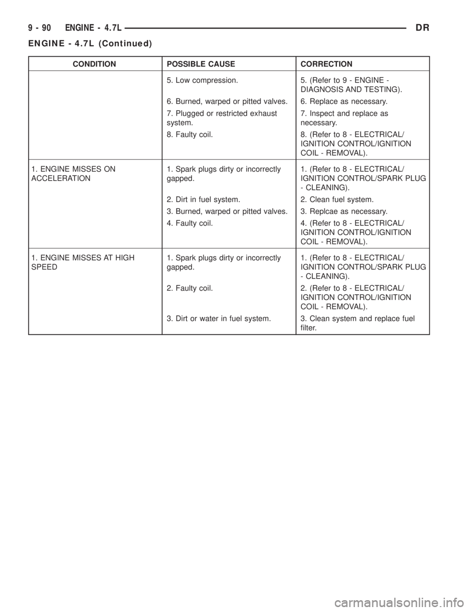
CONDITION POSSIBLE CAUSE CORRECTION
5. Low compression. 5. (Refer to 9 - ENGINE -
DIAGNOSIS AND TESTING).
6. Burned, warped or pitted valves. 6. Replace as necessary.
7. Plugged or restricted exhaust
system.7. Inspect and replace as
necessary.
8. Faulty coil. 8. (Refer to 8 - ELECTRICAL/
IGNITION CONTROL/IGNITION
COIL - REMOVAL).
1. ENGINE MISSES ON
ACCELERATION1. Spark plugs dirty or incorrectly
gapped.1. (Refer to 8 - ELECTRICAL/
IGNITION CONTROL/SPARK PLUG
- CLEANING).
2. Dirt in fuel system. 2. Clean fuel system.
3. Burned, warped or pitted valves. 3. Replcae as necessary.
4. Faulty coil. 4. (Refer to 8 - ELECTRICAL/
IGNITION CONTROL/IGNITION
COIL - REMOVAL).
1. ENGINE MISSES AT HIGH
SPEED1. Spark plugs dirty or incorrectly
gapped.1. (Refer to 8 - ELECTRICAL/
IGNITION CONTROL/SPARK PLUG
- CLEANING).
2. Faulty coil. 2. (Refer to 8 - ELECTRICAL/
IGNITION CONTROL/IGNITION
COIL - REMOVAL).
3. Dirt or water in fuel system. 3. Clean system and replace fuel
filter.
9 - 90 ENGINE - 4.7LDR
ENGINE - 4.7L (Continued)
Page 1342 of 2895
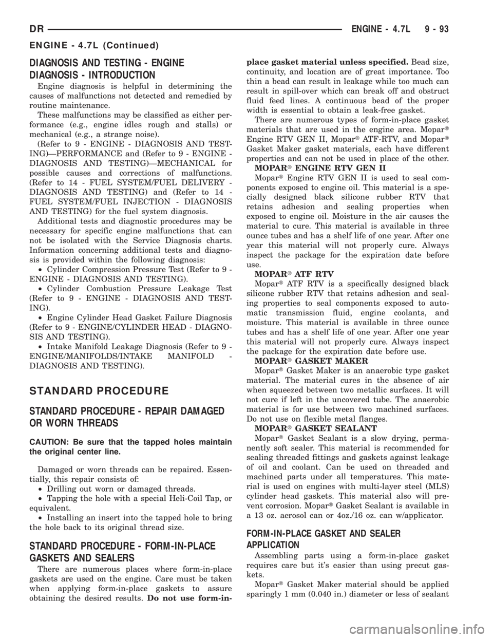
DIAGNOSIS AND TESTING - ENGINE
DIAGNOSIS - INTRODUCTION
Engine diagnosis is helpful in determining the
causes of malfunctions not detected and remedied by
routine maintenance.
These malfunctions may be classified as either per-
formance (e.g., engine idles rough and stalls) or
mechanical (e.g., a strange noise).
(Refer to 9 - ENGINE - DIAGNOSIS AND TEST-
ING)ÐPERFORMANCE and (Refer to 9 - ENGINE -
DIAGNOSIS AND TESTING)ÐMECHANICAL for
possible causes and corrections of malfunctions.
(Refer to 14 - FUEL SYSTEM/FUEL DELIVERY -
DIAGNOSIS AND TESTING) and (Refer to 14 -
FUEL SYSTEM/FUEL INJECTION - DIAGNOSIS
AND TESTING) for the fuel system diagnosis.
Additional tests and diagnostic procedures may be
necessary for specific engine malfunctions that can
not be isolated with the Service Diagnosis charts.
Information concerning additional tests and diagno-
sis is provided within the following diagnosis:
²Cylinder Compression Pressure Test (Refer to 9 -
ENGINE - DIAGNOSIS AND TESTING).
²Cylinder Combustion Pressure Leakage Test
(Refer to 9 - ENGINE - DIAGNOSIS AND TEST-
ING).
²Engine Cylinder Head Gasket Failure Diagnosis
(Refer to 9 - ENGINE/CYLINDER HEAD - DIAGNO-
SIS AND TESTING).
²Intake Manifold Leakage Diagnosis (Refer to 9 -
ENGINE/MANIFOLDS/INTAKE MANIFOLD -
DIAGNOSIS AND TESTING).
STANDARD PROCEDURE
STANDARD PROCEDURE - REPAIR DAMAGED
OR WORN THREADS
CAUTION: Be sure that the tapped holes maintain
the original center line.
Damaged or worn threads can be repaired. Essen-
tially, this repair consists of:
²Drilling out worn or damaged threads.
²Tapping the hole with a special Heli-Coil Tap, or
equivalent.
²Installing an insert into the tapped hole to bring
the hole back to its original thread size.
STANDARD PROCEDURE - FORM-IN-PLACE
GASKETS AND SEALERS
There are numerous places where form-in-place
gaskets are used on the engine. Care must be taken
when applying form-in-place gaskets to assure
obtaining the desired results.Do not use form-in-place gasket material unless specified.Bead size,
continuity, and location are of great importance. Too
thin a bead can result in leakage while too much can
result in spill-over which can break off and obstruct
fluid feed lines. A continuous bead of the proper
width is essential to obtain a leak-free gasket.
There are numerous types of form-in-place gasket
materials that are used in the engine area. Mopart
Engine RTV GEN II, MopartATF-RTV, and Mopart
Gasket Maker gasket materials, each have different
properties and can not be used in place of the other.
MOPARtENGINE RTV GEN II
MopartEngine RTV GEN II is used to seal com-
ponents exposed to engine oil. This material is a spe-
cially designed black silicone rubber RTV that
retains adhesion and sealing properties when
exposed to engine oil. Moisture in the air causes the
material to cure. This material is available in three
ounce tubes and has a shelf life of one year. After one
year this material will not properly cure. Always
inspect the package for the expiration date before
use.
MOPARtATF RTV
MopartATF RTV is a specifically designed black
silicone rubber RTV that retains adhesion and seal-
ing properties to seal components exposed to auto-
matic transmission fluid, engine coolants, and
moisture. This material is available in three ounce
tubes and has a shelf life of one year. After one year
this material will not properly cure. Always inspect
the package for the expiration date before use.
MOPARtGASKET MAKER
MopartGasket Maker is an anaerobic type gasket
material. The material cures in the absence of air
when squeezed between two metallic surfaces. It will
not cure if left in the uncovered tube. The anaerobic
material is for use between two machined surfaces.
Do not use on flexible metal flanges.
MOPARtGASKET SEALANT
MopartGasket Sealant is a slow drying, perma-
nently soft sealer. This material is recommended for
sealing threaded fittings and gaskets against leakage
of oil and coolant. Can be used on threaded and
machined parts under all temperatures. This mate-
rial is used on engines with multi-layer steel (MLS)
cylinder head gaskets. This material also will pre-
vent corrosion. MopartGasket Sealant is available in
a 13 oz. aerosol can or 4oz./16 oz. can w/applicator.
FORM-IN-PLACE GASKET AND SEALER
APPLICATION
Assembling parts using a form-in-place gasket
requires care but it's easier than using precut gas-
kets.
MopartGasket Maker material should be applied
sparingly 1 mm (0.040 in.) diameter or less of sealant
DRENGINE - 4.7L 9 - 93
ENGINE - 4.7L (Continued)
Page 1347 of 2895
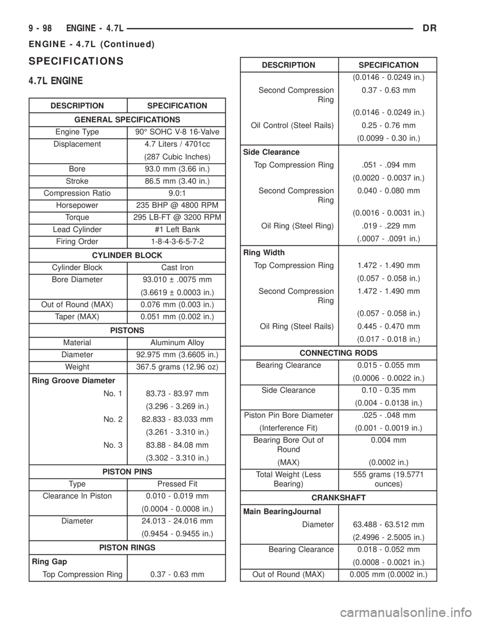
SPECIFICATIONS
4.7L ENGINE
DESCRIPTION SPECIFICATION
GENERAL SPECIFICATIONS
Engine Type 90É SOHC V-8 16-Valve
Displacement 4.7 Liters / 4701cc
(287 Cubic Inches)
Bore 93.0 mm (3.66 in.)
Stroke 86.5 mm (3.40 in.)
Compression Ratio 9.0:1
Horsepower 235 BHP @ 4800 RPM
Torque 295 LB-FT @ 3200 RPM
Lead Cylinder #1 Left Bank
Firing Order 1-8-4-3-6-5-7-2
CYLINDER BLOCK
Cylinder Block Cast Iron
Bore Diameter 93.010 .0075 mm
(3.6619 0.0003 in.)
Out of Round (MAX) 0.076 mm (0.003 in.)
Taper (MAX) 0.051 mm (0.002 in.)
PISTONS
Material Aluminum Alloy
Diameter 92.975 mm (3.6605 in.)
Weight 367.5 grams (12.96 oz)
Ring Groove Diameter
No. 1 83.73 - 83.97 mm
(3.296 - 3.269 in.)
No. 2 82.833 - 83.033 mm
(3.261 - 3.310 in.)
No. 3 83.88 - 84.08 mm
(3.302 - 3.310 in.)
PISTON PINS
Type Pressed Fit
Clearance In Piston 0.010 - 0.019 mm
(0.0004 - 0.0008 in.)
Diameter 24.013 - 24.016 mm
(0.9454 - 0.9455 in.)
PISTON RINGS
Ring Gap
Top Compression Ring 0.37 - 0.63 mm
DESCRIPTION SPECIFICATION
(0.0146 - 0.0249 in.)
Second Compression
Ring0.37 - 0.63 mm
(0.0146 - 0.0249 in.)
Oil Control (Steel Rails) 0.25 - 0.76 mm
(0.0099 - 0.30 in.)
Side Clearance
Top Compression Ring .051 - .094 mm
(0.0020 - 0.0037 in.)
Second Compression
Ring0.040 - 0.080 mm
(0.0016 - 0.0031 in.)
Oil Ring (Steel Ring) .019 - .229 mm
(.0007 - .0091 in.)
Ring Width
Top Compression Ring 1.472 - 1.490 mm
(0.057 - 0.058 in.)
Second Compression
Ring1.472 - 1.490 mm
(0.057 - 0.058 in.)
Oil Ring (Steel Rails) 0.445 - 0.470 mm
(0.017 - 0.018 in.)
CONNECTING RODS
Bearing Clearance 0.015 - 0.055 mm
(0.0006 - 0.0022 in.)
Side Clearance 0.10 - 0.35 mm
(0.004 - 0.0138 in.)
Piston Pin Bore Diameter .025 - .048 mm
(Interference Fit) (0.001 - 0.0019 in.)
Bearing Bore Out of
Round0.004 mm
(MAX) (0.0002 in.)
Total Weight (Less
Bearing)555 grams (19.5771
ounces)
CRANKSHAFT
Main BearingJournal
Diameter 63.488 - 63.512 mm
(2.4996 - 2.5005 in.)
Bearing Clearance 0.018 - 0.052 mm
(0.0008 - 0.0021 in.)
Out of Round (MAX) 0.005 mm (0.0002 in.)
9 - 98 ENGINE - 4.7LDR
ENGINE - 4.7L (Continued)
Page 1425 of 2895

ENGINE - 5.7L
TABLE OF CONTENTS
page page
ENGINE - 5.7L
DESCRIPTION........................178
DIAGNOSIS AND TESTING
DIAGNOSIS AND TESTING - ENGINE
DIAGNOSIS - INTRODUCTION..........178
DIAGNOSIS AND TESTING - ENGINE
DIAGNOSIS - PERFORMANCE..........179
DIAGNOSIS AND TESTING - ENGINE
DIAGNOSIS - MECHANICAL............181
DIAGNOSIS AND TESTING - CYLINDER
COMPRESSION PRESSURE............182
DIAGNOSIS AND TESTING - CYLINDER
COMBUSTION PRESSURE LEAKAGE.....182
DIAGNOSIS AND TESTINGÐENGINE
DIAGNOSIS - LUBRICATION............183
DIAGNOSIS AND TESTING - ENGINE
DIAGNOSIS - MECHANICAL............184
STANDARD PROCEDURE
STANDARD PROCEDURE - REPAIR
DAMAGED OR WORN THREADS........186
STANDARD PROCEDUREÐHYDROSTATIC
LOCK..............................186
REMOVAL............................186
INSTALLATION........................187
SPECIFICATIONS
5.7L ENGINE........................188
TORQUE...........................191
SPECIAL TOOLS
5.7L ENGINE........................192
AIR INTAKE SYSTEM
REMOVAL............................194
INSTALLATION........................194
CYLINDER HEAD
OPERATIONÐCYLINDER HEAD...........194
DIAGNOSIS AND TESTINGÐCYLINDER HEAD
GASKET FAILURE....................194
REMOVAL............................195
CLEANING...........................195
INSPECTION.........................195
INSTALLATION........................195
CYLINDER HEAD COVER(S)
REMOVAL............................196
INSTALLATION........................196
INTAKE/EXHAUST VALVES & SEATS
DESCRIPTION
DESCRIPTION - VALVE GUIDES.........197
DESCRIPTION.......................197
STANDARD PROCEDURE - REFACING.....197
REMOVAL............................198INSTALLATION........................198
ROCKER ARM / ADJUSTER ASSY
REMOVAL............................198
INSTALLATION........................198
VALVE STEM SEALS
DESCRIPTION........................198
VALVE SPRINGS
REMOVAL............................199
INSTALLATION........................199
ENGINE BLOCK
CLEANING...........................200
INSPECTION.........................200
CAMSHAFT & BEARINGS (IN BLOCK)
REMOVAL
REMOVAL - CAMSHAFT CORE HOLE PLUG. 200
REMOVAL - CAMSHAFT...............200
INSPECTION.........................201
INSTALLATION
INSTALLATION - CAMSHAFT CORE HOLE
PLUG..............................201
INSTALLATION - CAMSHAFT............201
CRANKSHAFT
REMOVAL............................201
INSTALLATION........................202
CRANKSHAFT MAIN BEARINGS
STANDARD PROCEDURE - CRANKSHAFT
MAIN BEARING - FITTING..............202
INSPECTION.........................203
CRANKSHAFT OIL SEAL - FRONT
REMOVAL............................203
INSTALLATION........................203
CRANKSHAFT OIL SEAL - REAR
DIAGNOSIS AND TESTING - REAR SEAL
AREA LEAKS........................204
REMOVAL............................204
INSTALLATION........................204
CRANKSHAFT REAR OIL SEAL RETAINER
REMOVAL............................204
INSTALLATION........................205
FLEX PLATE
REMOVAL............................205
INSTALLATION........................205
PISTON & CONNECTING ROD
DESCRIPTION........................205
STANDARD PROCEDUREÐPISTON FITTING . 205
REMOVAL............................205
CLEANING...........................206
INSPECTION.........................206
INSTALLATION........................207
9 - 176 ENGINE - 5.7LDR
Page 1429 of 2895
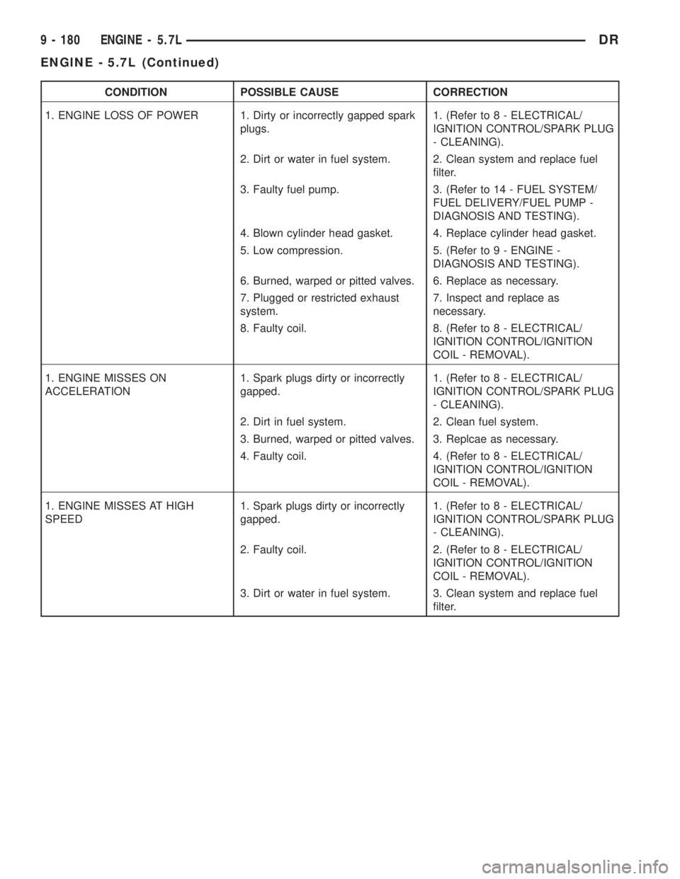
CONDITION POSSIBLE CAUSE CORRECTION
1. ENGINE LOSS OF POWER 1. Dirty or incorrectly gapped spark
plugs.1. (Refer to 8 - ELECTRICAL/
IGNITION CONTROL/SPARK PLUG
- CLEANING).
2. Dirt or water in fuel system. 2. Clean system and replace fuel
filter.
3. Faulty fuel pump. 3. (Refer to 14 - FUEL SYSTEM/
FUEL DELIVERY/FUEL PUMP -
DIAGNOSIS AND TESTING).
4. Blown cylinder head gasket. 4. Replace cylinder head gasket.
5. Low compression. 5. (Refer to 9 - ENGINE -
DIAGNOSIS AND TESTING).
6. Burned, warped or pitted valves. 6. Replace as necessary.
7. Plugged or restricted exhaust
system.7. Inspect and replace as
necessary.
8. Faulty coil. 8. (Refer to 8 - ELECTRICAL/
IGNITION CONTROL/IGNITION
COIL - REMOVAL).
1. ENGINE MISSES ON
ACCELERATION1. Spark plugs dirty or incorrectly
gapped.1. (Refer to 8 - ELECTRICAL/
IGNITION CONTROL/SPARK PLUG
- CLEANING).
2. Dirt in fuel system. 2. Clean fuel system.
3. Burned, warped or pitted valves. 3. Replcae as necessary.
4. Faulty coil. 4. (Refer to 8 - ELECTRICAL/
IGNITION CONTROL/IGNITION
COIL - REMOVAL).
1. ENGINE MISSES AT HIGH
SPEED1. Spark plugs dirty or incorrectly
gapped.1. (Refer to 8 - ELECTRICAL/
IGNITION CONTROL/SPARK PLUG
- CLEANING).
2. Faulty coil. 2. (Refer to 8 - ELECTRICAL/
IGNITION CONTROL/IGNITION
COIL - REMOVAL).
3. Dirt or water in fuel system. 3. Clean system and replace fuel
filter.
9 - 180 ENGINE - 5.7LDR
ENGINE - 5.7L (Continued)
Page 1437 of 2895
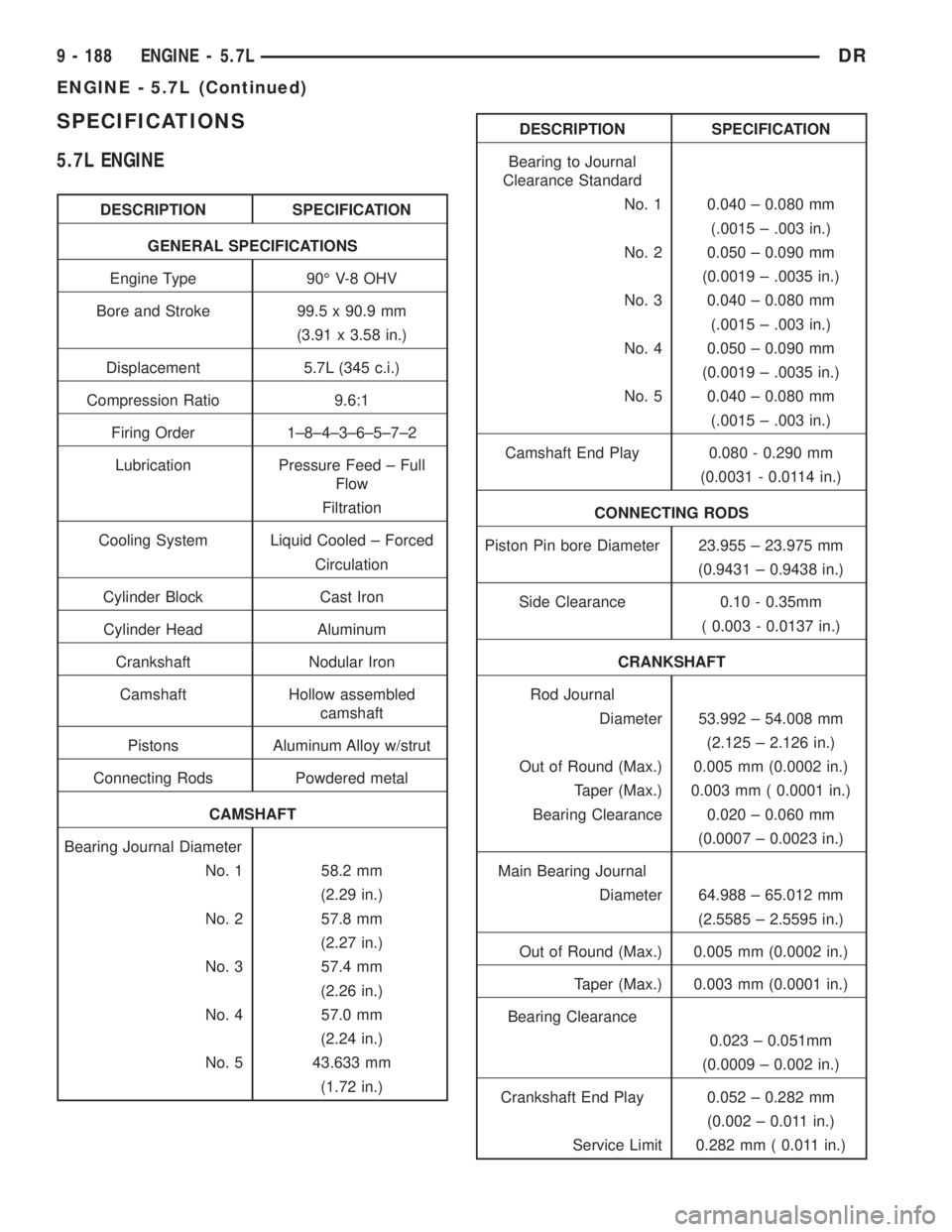
SPECIFICATIONS
5.7L ENGINE
DESCRIPTION SPECIFICATION
GENERAL SPECIFICATIONS
Engine Type 90É V-8 OHV
Bore and Stroke 99.5 x 90.9 mm
(3.91 x 3.58 in.)
Displacement 5.7L (345 c.i.)
Compression Ratio 9.6:1
Firing Order 1±8±4±3±6±5±7±2
Lubrication Pressure Feed ± Full
Flow
Filtration
Cooling System Liquid Cooled ± Forced
Circulation
Cylinder Block Cast Iron
Cylinder Head Aluminum
Crankshaft Nodular Iron
Camshaft Hollow assembled
camshaft
Pistons Aluminum Alloy w/strut
Connecting Rods Powdered metal
CAMSHAFT
Bearing Journal Diameter
No. 1 58.2 mm
(2.29 in.)
No. 2 57.8 mm
(2.27 in.)
No. 3 57.4 mm
(2.26 in.)
No. 4 57.0 mm
(2.24 in.)
No. 5 43.633 mm
(1.72 in.)
DESCRIPTION SPECIFICATION
Bearing to Journal
Clearance Standard
No. 1 0.040 ± 0.080 mm
(.0015 ± .003 in.)
No. 2 0.050 ± 0.090 mm
(0.0019 ± .0035 in.)
No. 3 0.040 ± 0.080 mm
(.0015 ± .003 in.)
No. 4 0.050 ± 0.090 mm
(0.0019 ± .0035 in.)
No. 5 0.040 ± 0.080 mm
(.0015 ± .003 in.)
Camshaft End Play 0.080 - 0.290 mm
(0.0031 - 0.0114 in.)
CONNECTING RODS
Piston Pin bore Diameter 23.955 ± 23.975 mm
(0.9431 ± 0.9438 in.)
Side Clearance 0.10 - 0.35mm
( 0.003 - 0.0137 in.)
CRANKSHAFT
Rod Journal
Diameter 53.992 ± 54.008 mm
(2.125 ± 2.126 in.)
Out of Round (Max.) 0.005 mm (0.0002 in.)
Taper (Max.) 0.003 mm ( 0.0001 in.)
Bearing Clearance 0.020 ± 0.060 mm
(0.0007 ± 0.0023 in.)
Main Bearing Journal
Diameter 64.988 ± 65.012 mm
(2.5585 ± 2.5595 in.)
Out of Round (Max.) 0.005 mm (0.0002 in.)
Taper (Max.) 0.003 mm (0.0001 in.)
Bearing Clearance
0.023 ± 0.051mm
(0.0009 ± 0.002 in.)
Crankshaft End Play 0.052 ± 0.282 mm
(0.002 ± 0.011 in.)
Service Limit 0.282 mm ( 0.011 in.)
9 - 188 ENGINE - 5.7LDR
ENGINE - 5.7L (Continued)
Page 1444 of 2895
þ Loss of engine power
þ Engine misfiring
þ Poor fuel economy
²Possible indications of the cylinder head gasket
leaking between a cylinder and an adjacent water
jacket are:
þ Engine overheating
þ Loss of coolant
þ Excessive steam (white smoke) emitting from
exhaust
þ Coolant foaming
CYLINDER-TO-CYLINDER LEAKAGE TEST
To determine if an engine cylinder head gasket is
leaking between adjacent cylinders, follow the proce-
dures in Cylinder Compression Pressure Test in this
section. An engine cylinder head gasket leaking
between adjacent cylinders will result in approxi-
mately a 50±70% reduction in compression pressure.
CYLINDER-TO-WATER JACKET LEAKAGE TEST
WARNING: USE EXTREME CAUTION WHEN THE
ENGINE IS OPERATING WITH COOLANT PRES-
SURE CAP REMOVED.
VISUAL TEST METHOD
With the engine cool, remove the coolant pressure
cap. Start the engine and allow it to warm up until
thermostat opens.
If a large combustion/compression pressure leak
exists, bubbles will be visible in the coolant.
COOLING SYSTEM TESTER METHOD
WARNING: WITH COOLING SYSTEM TESTER IN
PLACE, PRESSURE WILL BUILD UP FAST. EXCES-
SIVE PRESSURE BUILT UP, BY CONTINUOUS
ENGINE OPERATION, MUST BE RELEASED TO A
SAFE PRESSURE POINT. NEVER PERMIT PRES-
SURE TO EXCEED 138 kPa (20 psi).
Install Cooling System Tester 7700 or equivalent to
pressure cap neck. Start the engine and observe the
tester's pressure gauge. If gauge pulsates with every
power stroke of a cylinder a combustion pressure
leak is evident.
CHEMICAL TEST METHOD
Combustion leaks into the cooling system can also
be checked by using Bloc-Chek Kit C-3685-A or
equivalent. Perform test following the procedures
supplied with the tool kit.
REMOVAL
(1) Disconnect the battery negative cable.
(2) Drain cooling system.
(3) Remove the air cleaner resonator and duct
work.
(4) Remove the generator.
(5) Remove closed crankcase ventilation system.
(6) Disconnect the evaporation control system.
(7) Perform the Fuel System Pressure Release pro-
cedure (Refer to 14 - FUEL SYSTEM/FUEL DELIV-
ERY - STANDARD PROCEDURE). Disconnect the
fuel supply line (Refer to 14 - FUEL SYSTEM/FUEL
DELIVERY/QUICK CONNECT FITTING - STAN-
DARD PROCEDURE).
(8) Disconnect heater hoses.
(9) Remove cylinder head covers and gaskets.
(10) Remove intake manifold and throttle body as
an assembly.
(11) Remove rocker arm assemblies and push rods.
Identify to ensure installation in original locations.
(12) Remove the head bolts from each cylinder
head and remove cylinder heads. Discard the cylin-
der head gasket.
CLEANING
Clean all surfaces of cylinder block and cylinder
heads.
Clean cylinder block front and rear gasket surfaces
using a suitable solvent.
INSPECTION
(1) Inspect the cylinder head for out-of-flatness,
using a straightedge and a feeler gauge. If tolerances
exceed 0.0508 mm (0.002 in.) replace the cylinder
head.
(2) Inspect the valve seats for damage. Service the
valve seats as necessary.
(3) Inspect the valve guides for wear, cracks or
looseness. If either condition exist, replace the cylin-
der head.
(4) Inspect pushrods. Replace worn or bent push-
rods.
INSTALLATION
(1) Clean all surfaces of cylinder block and cylin-
der heads.
(2) Clean cylinder block front and rear gasket sur-
faces using a suitable solvent.
CAUTION: The head gaskets are not interchange-
able between left and right sides. They are marked
ªLº and ªRº to indicate left and right sides.
(3) Position new cylinder head gaskets onto the
cylinder block.
DRENGINE - 5.7L 9 - 195
CYLINDER HEAD (Continued)
Page 1472 of 2895
ENGINE - 5.9L
TABLE OF CONTENTS
page page
ENGINE - 5.9L
DESCRIPTION........................224
DIAGNOSIS AND TESTING
DIAGNOSIS AND TESTING - ENGINE
DIAGNOSIS - INTRODUCTION..........225
DIAGNOSIS AND TESTINGÐENGINE
DIAGNOSIS - PERFORMANCE..........226
DIAGNOSIS AND TESTING - ENGINE
DIAGNOSIS - MECHANICAL............228
DIAGNOSIS AND TESTINGÐENGINE
DIAGNOSIS - LUBRICATION............230
DIAGNOSIS AND TESTINGÐCYLINDER
COMPRESSION PRESSURE............231
DIAGNOSIS AND TESTING - CYLINDER
COMBUSTION PRESSURE LEAKAGE.....231
STANDARD PROCEDURE
STANDARD PROCEDURE - FORM-IN-
PLACE GASKETS AND SEALERS........232
STANDARD PROCEDURE - REPAIR
DAMAGED OR WORN THREADS........232
STANDARD PROCEDUREÐHYDROSTATIC
LOCK..............................232
STANDARD PROCEDURE - CYLINDER
BORE HONING......................233
REMOVAL............................233
INSTALLATION........................234
SPECIFICATIONS
5.9L ENGINE........................235
TORQUE...........................239
SPECIAL TOOLS
5.9L ENGINE........................240
AIR CLEANER ELEMENT
REMOVAL............................242
INSTALLATION........................242
CYLINDER HEAD
DESCRIPTION
DESCRIPTIONÐCYLINDER HEAD.......243
DESCRIPTION - CYLINDER HEAD COVER
GASKET...........................243
OPERATION
OPERATIONÐCYLINDER HEAD.........243
OPERATION - CYLINDER HEAD COVER
GASKET...........................243
DIAGNOSIS AND TESTINGÐCYLINDER HEAD
GASKET FAILURE....................243
REMOVAL............................244
CLEANING...........................244
INSPECTION.........................244
INSTALLATION........................244CYLINDER HEAD COVER(S)
REMOVAL............................245
CLEANING...........................245
INSPECTION.........................245
INSTALLATION........................245
INTAKE/EXHAUST VALVES & SEATS
DESCRIPTION........................246
STANDARD PROCEDUREÐVALVES, GUIDES
AND SPRINGS.......................246
REMOVAL............................248
CLEANING...........................248
INSPECTION.........................248
INSTALLATION........................248
ROCKER ARM / ADJUSTER ASSEMBLY
REMOVAL............................249
INSTALLATION........................249
ENGINE BLOCK
CLEANING...........................249
INSPECTION.........................249
CAMSHAFT & BEARINGS (IN BLOCK)
REMOVALÐCAMSHAFT.................250
INSTALLATIONÐCAMSHAFT.............250
CONNECTING ROD BEARINGS
STANDARD PROCEDURE - CONNECTING
ROD BEARING FITTING...............251
CRANKSHAFT
DESCRIPTION........................252
OPERATION..........................252
REMOVAL............................252
INSTALLATION........................252
CRANKSHAFT MAIN BEARINGS
DESCRIPTION........................253
OPERATION..........................253
STANDARD PROCEDUREÐCRANKSHAFT
MAIN BEARING FITTING...............253
REMOVAL............................254
INSTALLATION........................254
CRANKSHAFT OIL SEAL - FRONT
DESCRIPTION........................254
OPERATION..........................254
REMOVAL............................254
INSTALLATION........................255
CRANKSHAFT OIL SEAL - REAR
DESCRIPTION........................255
OPERATION..........................255
REMOVAL............................255
INSTALLATION........................256
DISTRIBUTOR BUSHING
REMOVAL............................258
INSTALLATION........................258
DRENGINE - 5.9L 9 - 223