2003 DODGE RAM compression ratio
[x] Cancel search: compression ratioPage 1484 of 2895
(19) Install the distributor cap and wiring.
(20) Install the intake manifold (Refer to 9 -
ENGINE/MANIFOLDS/INTAKE MANIFOLD -
INSTALLATION).
(21) Using a new gasket, install throttle body
(Refer to 14 - FUEL SYSTEM/FUEL INJECTION/
THROTTLE BODY - INSTALLATION).
(22) Connect the throttle linkage (Refer to 14 -
FUEL SYSTEM/FUEL INJECTION/THROTTLE
CONTROL CABLE - INSTALLATION).
(23) Install the air cleaner resonator and duct
work..
(24) Install the generator and wire connections
(Refer to 8 - ELECTRICAL/CHARGING/GENERA-
TOR - INSTALLATION).
(25) Install a/c compressor and lines (Refer to 24 -
HEATING & AIR CONDITIONING/PLUMBING/A/C
COMPRESSOR - INSTALLATION).
(26) Install the accessory drive belt (Refer to 7 -
COOLING/ACCESSORY DRIVE/DRIVE BELTS -
INSTALLATION).
(27) Install upper radiator support crossmember.
(28) Install radiator (Refer to 7 - COOLING/EN-
GINE/RADIATOR - INSTALLATION).
(29) Connect the radiator lower hose.
(30) Connect the transmission oil cooler lines to
the radiator.
(31) Install the fan shroud.
(32) Install the fan (Refer to 7 - COOLING/EN-
GINE/RADIATOR FAN - INSTALLATION).
(33) Connect the radiator upper hose.
(34) Install the washer bottle.
(35) Install the transmission oil cooler (Refer to 7 -
COOLING/TRANSMISSION/TRANS COOLER -
INSTALLATION).
(36) Connect the transmission cooler lines.
(37) If equipped, install the condenser (Refer to 24
- HEATING & AIR CONDITIONING/PLUMBING/
A/C CONDENSER - INSTALLATION).
(38) Evacuate and charge the air conditioning sys-
tem, if equipped (Refer to 24 - HEATING & AIR
CONDITIONING/PLUMBING - STANDARD PRO-
CEDURE).
(39) Add engine oil to crankcase (Refer to LUBRI-
CATION & MAINTENANCE/FLUID TYPES - SPEC-
IFICATIONS).
(40) Fill cooling system (Refer to 7 - COOLING -
STANDARD PROCEDURE).
(41) Connect battery negative cable.
(42) Start engine and inspect for leaks.
(43) Road test vehicle.SPECIFICATIONS
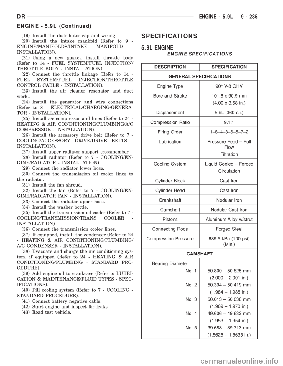
5.9L ENGINE
ENGINE SPECIFICATIONS
DESCRIPTION SPECIFICATION
GENERAL SPECIFICATIONS
Engine Type 90É V-8 OHV
Bore and Stroke 101.6 x 90.9 mm
(4.00 x 3.58 in.)
Displacement 5.9L (360 c.i.)
Compression Ratio 9.1:1
Firing Order 1±8±4±3±6±5±7±2
Lubrication Pressure Feed ± Full
Flow
Filtration
Cooling System Liquid Cooled ± Forced
Circulation
Cylinder Block Cast Iron
Cylinder Head Cast Iron
Crankshaft Nodular Iron
Camshaft Nodular Cast Iron
Pistons Aluminum Alloy w/strut
Connecting Rods Forged Steel
Compression Pressure 689.5 kPa (100 psi)
(Min.)
CAMSHAFT
Bearing Diameter
No. 1 50.800 ± 50.825 mm
(2.000 ± 2.001 in.)
No. 2 50.394 ± 50.419 mm
(1.984 ± 1.985 in.)
No. 3 50.013 ± 50.038 mm
(1.969 ± 1.970 in.)
No. 4 49.606 ± 49.632 mm
(1.953 ± 1.954 in.)
No. 5 39.688 ± 39.713 mm
(1.5625 ± 1.5635 in.)
DRENGINE - 5.9L 9 - 235
ENGINE - 5.9L (Continued)
Page 1487 of 2895
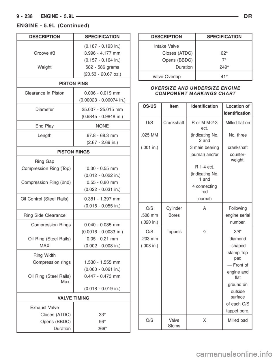
DESCRIPTION SPECIFICATION
(0.187 - 0.193 in.)
Groove #3 3.996 - 4.177 mm
(0.157 - 0.164 in.)
Weight 582 - 586 grams
(20.53 - 20.67 oz.)
PISTON PINS
Clearance in Piston 0.006 - 0.019 mm
(0.00023 - 0.00074 in.)
Diameter 25.007 - 25.015 mm
(0.9845 - 0.9848 in.)
End Play NONE
Length 67.8 - 68.3 mm
(2.67 - 2.69 in.)
PISTON RINGS
Ring Gap
Compression Ring (Top) 0.30 - 0.55 mm
(0.012 - 0.022 in.)
Compression Ring (2nd) 0.55 - 0.80 mm
(0.022 - 0.031 in.)
Oil Control (Steel Rails) 0.381 - 1.397 mm
(0.015 - 0.055 in.)
Ring Side Clearance
Compression Rings 0.040 - 0.085 mm
(0.0016 - 0.0033 in.)
Oil Ring (Steel Rails) 0.05 - 0.21 mm
MAX (0.002 - 0.008 in.)
Ring Width
Compression rings 1.530 - 1.555 mm
(0.060 - 0.061 in.)
Oil Ring (Steel Rails)
Max.0.447 - 0.473 mm
(0.018 - 0.019 in.)
VALVE TIMING
Exhaust Valve
Closes (ATDC) 33É
Opens (BBDC) 56É
Duration 269ÉDESCRIPTION SPECIFICATION
Intake Valve
Closes (ATDC) 62É
Opens (BBDC) 7É
Duration 249É
Valve Overlap 41É
OVERSIZE AND UNDERSIZE ENGINE
COMPONENT MARKINGS CHART
OS-US Item Identification Location of
Identification
U/S Crankshaft R or M M-2-3
ect.Milled flat on
.025 MM (indicating No.
2 andNo. three
(.001 in.) 3 main bearing crankshaft
journal) and/or counter-
weight.
R-1-4 ect.
(indicating No.
1 and
4 connecting
rod
journal)
O/S Cylinder A Following
.508 mm Bores engine serial
(.020 in.) number.
O/S TappetsL3/89
.203 mm diamond
(.008 in.) -shaped
stamp Top
pad
Ð Front of
engine and
flat
ground on
outside
surface
of each O/S
tappet bore.
O/S Valve
StemsX Milled pad
9 - 238 ENGINE - 5.9LDR
ENGINE - 5.9L (Continued)
Page 1492 of 2895
CYLINDER HEAD
DESCRIPTION
DESCRIPTIONÐCYLINDER HEAD
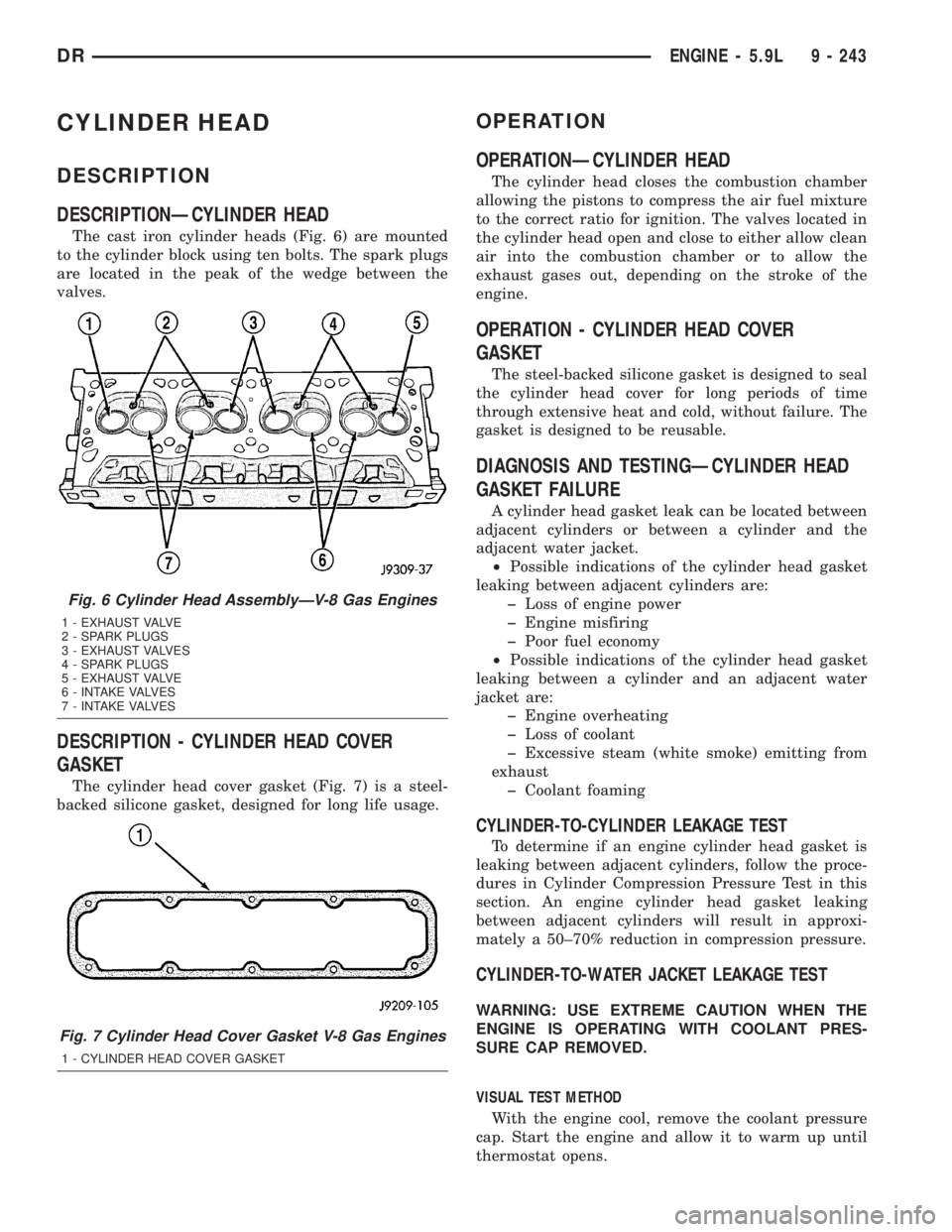
The cast iron cylinder heads (Fig. 6) are mounted
to the cylinder block using ten bolts. The spark plugs
are located in the peak of the wedge between the
valves.
DESCRIPTION - CYLINDER HEAD COVER
GASKET
The cylinder head cover gasket (Fig. 7) is a steel-
backed silicone gasket, designed for long life usage.
OPERATION
OPERATIONÐCYLINDER HEAD
The cylinder head closes the combustion chamber
allowing the pistons to compress the air fuel mixture
to the correct ratio for ignition. The valves located in
the cylinder head open and close to either allow clean
air into the combustion chamber or to allow the
exhaust gases out, depending on the stroke of the
engine.
OPERATION - CYLINDER HEAD COVER
GASKET
The steel-backed silicone gasket is designed to seal
the cylinder head cover for long periods of time
through extensive heat and cold, without failure. The
gasket is designed to be reusable.
DIAGNOSIS AND TESTINGÐCYLINDER HEAD
GASKET FAILURE
A cylinder head gasket leak can be located between
adjacent cylinders or between a cylinder and the
adjacent water jacket.
²Possible indications of the cylinder head gasket
leaking between adjacent cylinders are:
þ Loss of engine power
þ Engine misfiring
þ Poor fuel economy
²Possible indications of the cylinder head gasket
leaking between a cylinder and an adjacent water
jacket are:
þ Engine overheating
þ Loss of coolant
þ Excessive steam (white smoke) emitting from
exhaust
þ Coolant foaming
CYLINDER-TO-CYLINDER LEAKAGE TEST
To determine if an engine cylinder head gasket is
leaking between adjacent cylinders, follow the proce-
dures in Cylinder Compression Pressure Test in this
section. An engine cylinder head gasket leaking
between adjacent cylinders will result in approxi-
mately a 50±70% reduction in compression pressure.
CYLINDER-TO-WATER JACKET LEAKAGE TEST
WARNING: USE EXTREME CAUTION WHEN THE
ENGINE IS OPERATING WITH COOLANT PRES-
SURE CAP REMOVED.
VISUAL TEST METHOD
With the engine cool, remove the coolant pressure
cap. Start the engine and allow it to warm up until
thermostat opens.
Fig. 6 Cylinder Head AssemblyÐV-8 Gas Engines
1 - EXHAUST VALVE
2 - SPARK PLUGS
3 - EXHAUST VALVES
4 - SPARK PLUGS
5 - EXHAUST VALVE
6 - INTAKE VALVES
7 - INTAKE VALVES
Fig. 7 Cylinder Head Cover Gasket V-8 Gas Engines
1 - CYLINDER HEAD COVER GASKET
DRENGINE - 5.9L 9 - 243
Page 1493 of 2895
If a large combustion/compression pressure leak
exists, bubbles will be visible in the coolant.
COOLING SYSTEM TESTER METHOD
WARNING: WITH COOLING SYSTEM TESTER IN
PLACE, PRESSURE WILL BUILD UP FAST. EXCES-
SIVE PRESSURE BUILT UP, BY CONTINUOUS
ENGINE OPERATION, MUST BE RELEASED TO A
SAFE PRESSURE POINT. NEVER PERMIT PRES-
SURE TO EXCEED 138 kPa (20 psi).
Install Cooling System Tester 7700 or equivalent to
pressure cap neck. Start the engine and observe the
tester's pressure gauge. If gauge pulsates with every
power stroke of a cylinder a combustion pressure
leak is evident.
CHEMICAL TEST METHOD
Combustion leaks into the cooling system can also
be checked by using Bloc-Chek Kit C-3685-A or
equivalent. Perform test following the procedures
supplied with the tool kit.
REMOVAL
(1) Disconnect the battery negative cable.
(2) Drain cooling system (Refer to 7 - COOLING -
STANDARD PROCEDURE).
(3) Remove the air cleaner resonator and duct
work.
(4) Remove the intake manifold-to-generator
bracket support rod. Remove the generator.
(5) Remove closed crankcase ventilation system.
(6) Disconnect the evaporation control system.
(7) Perform the Fuel System Pressure Release pro-
cedure (Refer to 14 - FUEL SYSTEM/FUEL DELIV-
ERY - STANDARD PROCEDURE). Disconnect the
fuel supply line (Refer to 14 - FUEL SYSTEM/FUEL
DELIVERY/QUICK CONNECT FITTING - STAN-
DARD PROCEDURE).
(8) Disconnect accelerator linkage and if so
equipped, the speed control and transmission kick-
down cables.
(9) Remove distributor cap and wires.
(10) Disconnect the coil wires.
(11) Disconnect heat indicator sending unit wire.
(12) Disconnect heater hoses and bypass hose.
(13) Remove the master cylinder and booster
assembly. Refer to section 5 brakes.
(14) Remove cylinder head covers and gaskets
(Refer to 9 - ENGINE/CYLINDER HEAD/CYLIN-
DER HEAD COVER(S) - REMOVAL).
(15) Remove intake manifold (Refer to 9 -
ENGINE/MANIFOLDS/INTAKE MANIFOLD -
REMOVAL) and throttle body as an assembly. Dis-
card the flange side gaskets and the front and rear
cross-over gaskets.(16) Remove exhaust manifolds (Refer to 9 -
ENGINE/MANIFOLDS/EXHAUST MANIFOLD -
REMOVAL).
(17) Remove rocker arm assemblies and push rods.
Identify to ensure installation in original locations.
(18) Remove the head bolts from each cylinder
head and remove cylinder heads. Discard the cylin-
der head gasket.
(19) Remove spark plugs.
CLEANING
Clean all surfaces of cylinder block and cylinder
heads.
Clean cylinder block front and rear gasket surfaces
using a suitable solvent.
INSPECTION
Inspect all surfaces with a straightedge if there is
any reason to suspect leakage. If out-of-flatness
exceeds 0.00075mm/mm (0.0001in/in.) times the span
length in any direction, either replace head or lightly
machine the head surface.
FOR EXAMPLE:ÐA 305 mm (12 in.) span is
0.102 mm (0.004 in.) out-of-flat. The allowable out-of-
flat is 305 x 0.00075 (12 x 0.00075) equals 0.23 mm
(0.009 in.). This amount of out-of-flat is acceptable.
The cylinder head surface finish should be
1.78-3.00 microns (70-125 microinches).
Inspect push rods. Replace worn or bent rods.
INSTALLATION
(1) Clean all surfaces of cylinder block and cylin-
der heads.
(2) Clean cylinder block front and rear gasket sur-
faces using a suitable solvent.
(3) Position new cylinder head gaskets onto the
cylinder block.
(4) Position cylinder heads onto head gaskets and
cylinder block.
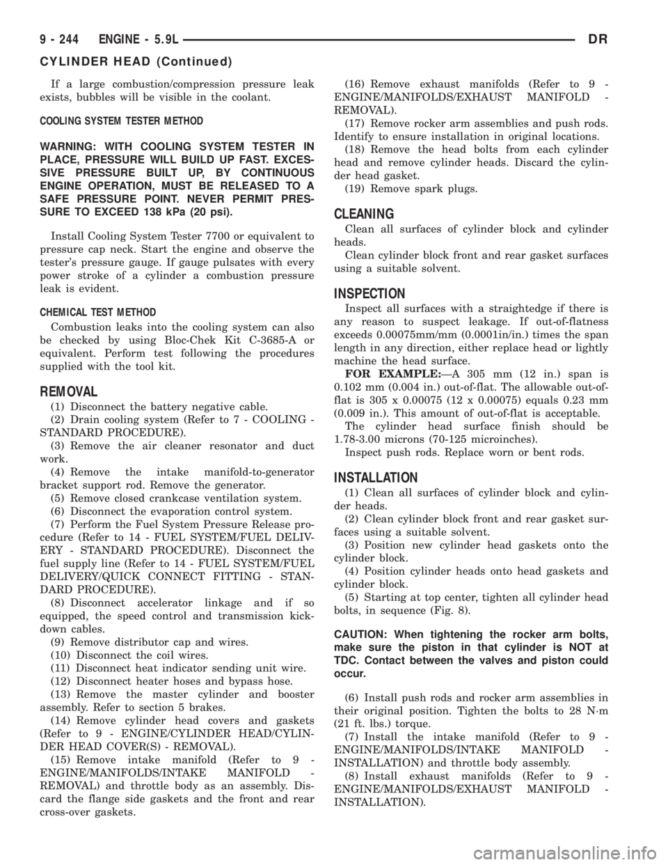
(5) Starting at top center, tighten all cylinder head
bolts, in sequence (Fig. 8).
CAUTION: When tightening the rocker arm bolts,
make sure the piston in that cylinder is NOT at
TDC. Contact between the valves and piston could
occur.
(6) Install push rods and rocker arm assemblies in
their original position. Tighten the bolts to 28 N´m
(21 ft. lbs.) torque.
(7) Install the intake manifold (Refer to 9 -
ENGINE/MANIFOLDS/INTAKE MANIFOLD -
INSTALLATION) and throttle body assembly.
(8) Install exhaust manifolds (Refer to 9 -
ENGINE/MANIFOLDS/EXHAUST MANIFOLD -
INSTALLATION).
9 - 244 ENGINE - 5.9LDR
CYLINDER HEAD (Continued)
Page 1510 of 2895
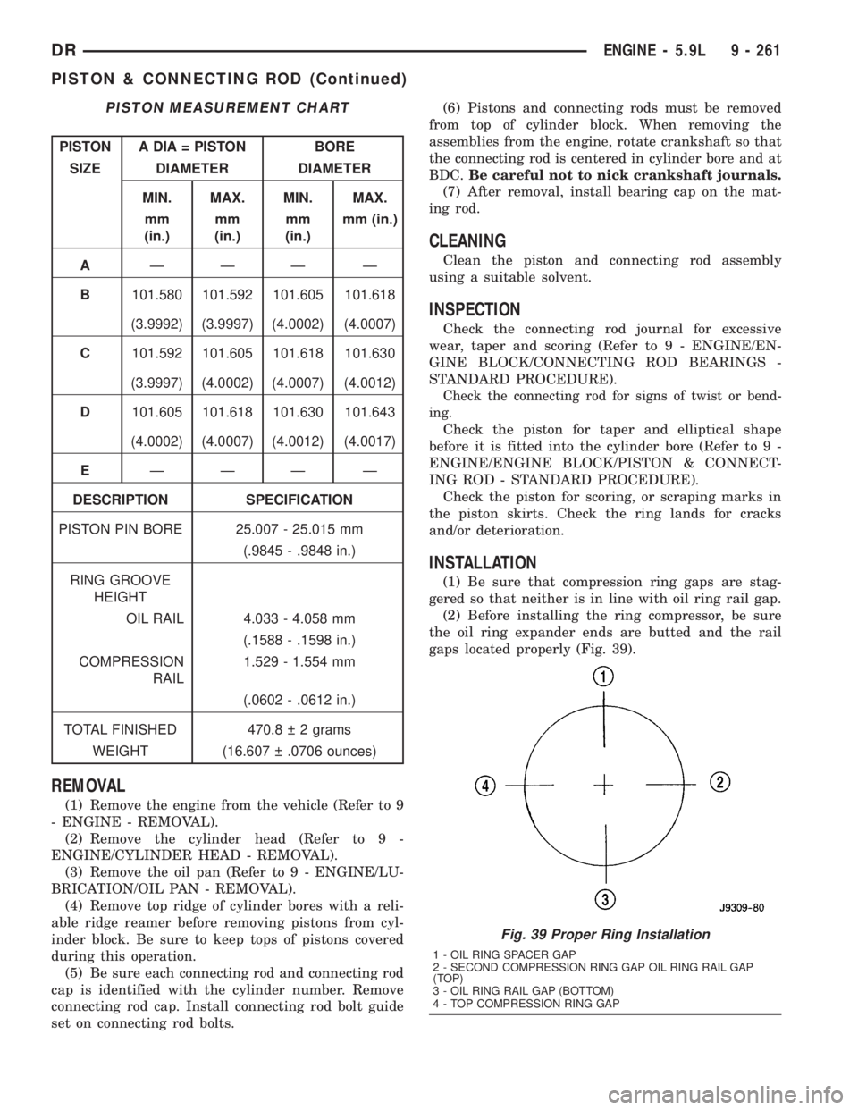
PISTON MEASUREMENT CHART
PISTON A DIA = PISTON BORE
SIZE DIAMETER DIAMETER
MIN. MAX. MIN. MAX.
mm
(in.)mm
(in.)mm
(in.)mm (in.)
AÐÐÐ Ð
B101.580 101.592 101.605 101.618
(3.9992) (3.9997) (4.0002) (4.0007)
C101.592 101.605 101.618 101.630
(3.9997) (4.0002) (4.0007) (4.0012)
D101.605 101.618 101.630 101.643
(4.0002) (4.0007) (4.0012) (4.0017)
EÐÐÐ Ð
DESCRIPTION SPECIFICATION
PISTON PIN BORE 25.007 - 25.015 mm
(.9845 - .9848 in.)
RING GROOVE
HEIGHT
OIL RAIL 4.033 - 4.058 mm
(.1588 - .1598 in.)
COMPRESSION
RAIL1.529 - 1.554 mm
(.0602 - .0612 in.)
TOTAL FINISHED 470.8 2 grams
WEIGHT (16.607 .0706 ounces)
REMOVAL
(1) Remove the engine from the vehicle (Refer to 9
- ENGINE - REMOVAL).
(2) Remove the cylinder head (Refer to 9 -
ENGINE/CYLINDER HEAD - REMOVAL).
(3) Remove the oil pan (Refer to 9 - ENGINE/LU-
BRICATION/OIL PAN - REMOVAL).
(4) Remove top ridge of cylinder bores with a reli-
able ridge reamer before removing pistons from cyl-
inder block. Be sure to keep tops of pistons covered
during this operation.
(5) Be sure each connecting rod and connecting rod
cap is identified with the cylinder number. Remove
connecting rod cap. Install connecting rod bolt guide
set on connecting rod bolts.(6) Pistons and connecting rods must be removed
from top of cylinder block. When removing the
assemblies from the engine, rotate crankshaft so that
the connecting rod is centered in cylinder bore and at
BDC.Be careful not to nick crankshaft journals.
(7) After removal, install bearing cap on the mat-
ing rod.
CLEANING
Clean the piston and connecting rod assembly
using a suitable solvent.
INSPECTION
Check the connecting rod journal for excessive
wear, taper and scoring (Refer to 9 - ENGINE/EN-
GINE BLOCK/CONNECTING ROD BEARINGS -
STANDARD PROCEDURE).
Check the connecting rod for signs of twist or bend-
ing.
Check the piston for taper and elliptical shape
before it is fitted into the cylinder bore (Refer to 9 -
ENGINE/ENGINE BLOCK/PISTON & CONNECT-
ING ROD - STANDARD PROCEDURE).
Check the piston for scoring, or scraping marks in
the piston skirts. Check the ring lands for cracks
and/or deterioration.
INSTALLATION
(1) Be sure that compression ring gaps are stag-
gered so that neither is in line with oil ring rail gap.
(2) Before installing the ring compressor, be sure
the oil ring expander ends are butted and the rail
gaps located properly (Fig. 39).
Fig. 39 Proper Ring Installation
1 - OIL RING SPACER GAP
2 - SECOND COMPRESSION RING GAP OIL RING RAIL GAP
(TOP)
3 - OIL RING RAIL GAP (BOTTOM)
4 - TOP COMPRESSION RING GAP
DRENGINE - 5.9L 9 - 261
PISTON & CONNECTING ROD (Continued)
Page 1511 of 2895
(3) Immerse the piston head and rings in clean
engine oil. Slide Piston Ring Compressor Tool C-385
over the piston and tighten with the special wrench
(part of Tool C-385).Be sure position of rings
does not change during this operation.
(4) Install connecting rod bolt protectors on rod
bolts. The long protector should be installed on the
numbered side of the connecting rod.
(5) Rotate crankshaft so that the connecting rod
journal is on the center of the cylinder bore. Be sure
connecting rod and cylinder bore number are the
same. Insert rod and piston into cylinder bore and
guide rod over the crankshaft journal.
(6) Tap the piston down in cylinder bore, using a
hammer handle. At the same time, guide connecting
rod into position on crankshaft journal.
(7) The notch, or groove, on top of piston must be
pointing toward front of engine. The larger chamfer
of the connecting rod bore must be installed toward
crankshaft journal fillet.
(8) Install rod caps. Be sure connecting rod, con-
necting rod cap, and cylinder bore number are the
same. Install nuts on cleaned and oiled rod bolts and
tighten nuts to 61 N´m (45 ft. lbs.) torque.
(9) Install the oil pan (Refer to 9 - ENGINE/LU-
BRICATION/OIL PAN - INSTALLATION).
(10) Install the cylinder head (Refer to 9 -
ENGINE/CYLINDER HEAD - INSTALLATION).
(11) Install the engine into the vehicle (Refer to 9 -
ENGINE - INSTALLATION).
PISTON RINGS
STANDARD PROCEDURE - PISTON RING
FITTING
(1) Measurement of end gaps:
(a) Measure piston ring gap 2 in. from bottom of
cylinder bore. An inverted piston can be used to
push the rings down to ensure positioning rings
squarely in the cylinder bore before measuring.
(b) Insert feeler gauge in the gap. The top com-
pression ring gap should be between 0.254-0.508
mm (0.010-0.020 in.). The second compression ring
gap should be between 0.508-0.762 mm
(0.020-0.030 in.). The oil ring gap should be 0.254-
1.270 mm (0.010-0.050 in.).
(c) Rings with insufficient end gap may be prop-
erly filed to the correct dimension. Rings with
excess gaps should not be used.
(2) Install rings, and confirm ring side clearance:
(a)
Install oil rings being careful not to nick or
scratch the piston. Install the oil control rings accord-
ing to instructions in the package. It is not necessary
to use a tool to install the upper and lower rails.
Insert oil rail spacer first, then side rails.
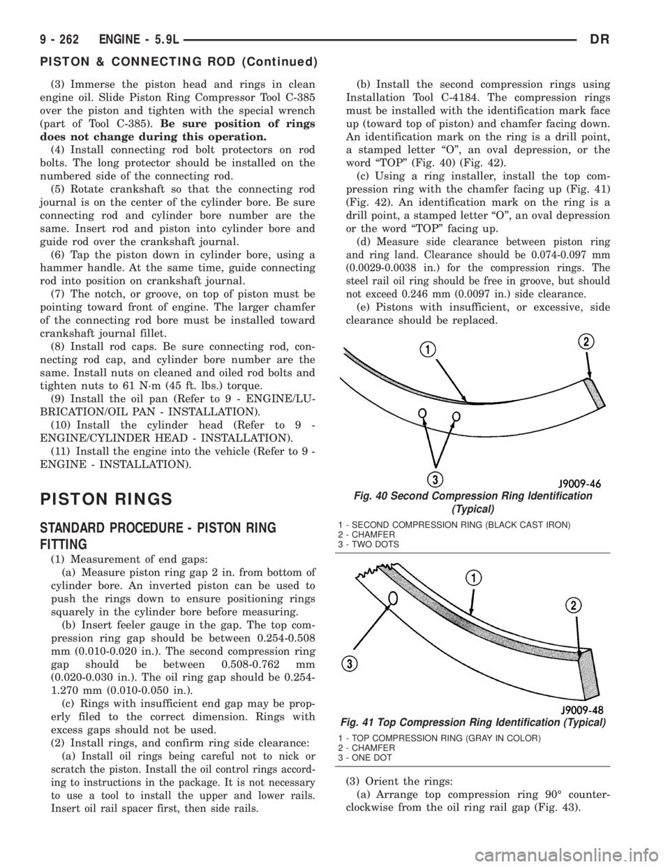
(b) Install the second compression rings using
Installation Tool C-4184. The compression rings
must be installed with the identification mark face
up (toward top of piston) and chamfer facing down.
An identification mark on the ring is a drill point,
a stamped letter ªOº, an oval depression, or the
word ªTOPº (Fig. 40) (Fig. 42).
(c) Using a ring installer, install the top com-
pression ring with the chamfer facing up (Fig. 41)
(Fig. 42). An identification mark on the ring is a
drill point, a stamped letter ªOº, an oval depression
or the word ªTOPº facing up.
(d) M
easure side clearance between piston ring
and ring land. Clearance should be 0.074-0.097 mm
(0.0029-0.0038 in.) for the compression rings. The
steel rail oil ring should be free in groove, but should
not exceed 0.246 mm (0.0097 in.) side clearance.
(e) Pistons with insufficient, or excessive, side
clearance should be replaced.
(3) Orient the rings:
(a) Arrange top compression ring 90É counter-
clockwise from the oil ring rail gap (Fig. 43).
Fig. 40 Second Compression Ring Identification
(Typical)
1 - SECOND COMPRESSION RING (BLACK CAST IRON)
2 - CHAMFER
3 - TWO DOTS
Fig. 41 Top Compression Ring Identification (Typical)
1 - TOP COMPRESSION RING (GRAY IN COLOR)
2 - CHAMFER
3 - ONE DOT
9 - 262 ENGINE - 5.9LDR
PISTON & CONNECTING ROD (Continued)
Page 1512 of 2895
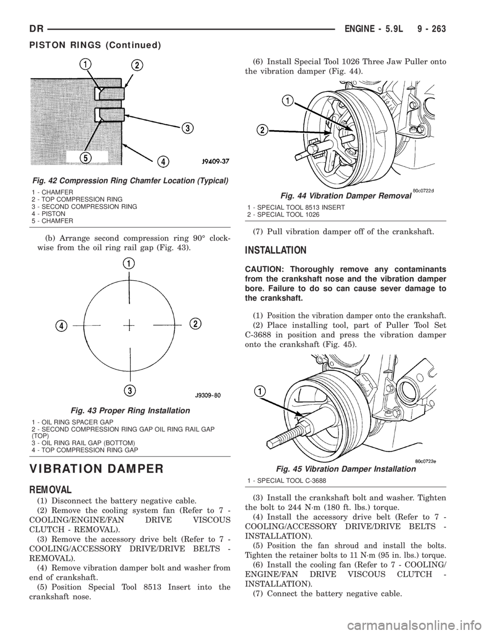
(b) Arrange second compression ring 90É clock-
wise from the oil ring rail gap (Fig. 43).
VIBRATION DAMPER
REMOVAL
(1) Disconnect the battery negative cable.
(2) Remove the cooling system fan (Refer to 7 -
COOLING/ENGINE/FAN DRIVE VISCOUS
CLUTCH - REMOVAL).
(3) Remove the accessory drive belt (Refer to 7 -
COOLING/ACCESSORY DRIVE/DRIVE BELTS -
REMOVAL).
(4) Remove vibration damper bolt and washer from
end of crankshaft.
(5) Position Special Tool 8513 Insert into the
crankshaft nose.(6) Install Special Tool 1026 Three Jaw Puller onto
the vibration damper (Fig. 44).
(7) Pull vibration damper off of the crankshaft.
INSTALLATION
CAUTION: Thoroughly remove any contaminants
from the crankshaft nose and the vibration damper
bore. Failure to do so can cause sever damage to
the crankshaft.
(1)
Position the vibration damper onto the crankshaft.
(2) Place installing tool, part of Puller Tool Set
C-3688 in position and press the vibration damper
onto the crankshaft (Fig. 45).
(3) Install the crankshaft bolt and washer. Tighten
the bolt to 244 N´m (180 ft. lbs.) torque.
(4) Install the accessory drive belt (Refer to 7 -
COOLING/ACCESSORY DRIVE/DRIVE BELTS -
INSTALLATION).
(5)
Position the fan shroud and install the bolts.
Tighten the retainer bolts to 11 N´m (95 in. lbs.) torque.
(6) Install the cooling fan (Refer to 7 - COOLING/
ENGINE/FAN DRIVE VISCOUS CLUTCH -
INSTALLATION).
(7) Connect the battery negative cable.
Fig. 42 Compression Ring Chamfer Location (Typical)
1 - CHAMFER
2 - TOP COMPRESSION RING
3 - SECOND COMPRESSION RING
4 - PISTON
5 - CHAMFER
Fig. 43 Proper Ring Installation
1 - OIL RING SPACER GAP
2 - SECOND COMPRESSION RING GAP OIL RING RAIL GAP
(TOP)
3 - OIL RING RAIL GAP (BOTTOM)
4 - TOP COMPRESSION RING GAP
Fig. 44 Vibration Damper Removal
1 - SPECIAL TOOL 8513 INSERT
2 - SPECIAL TOOL 1026
Fig. 45 Vibration Damper Installation
1 - SPECIAL TOOL C-3688
DRENGINE - 5.9L 9 - 263
PISTON RINGS (Continued)
Page 1533 of 2895
CONDITION POSSIBLE CAUSES CORRECTION
LUBRICATING OIL LOSS 1. External leaks. 1. Visually inspect for oil leaks. Repair as
required.
2. Crankcase being overfilled. 2. Verify that the correct dipstick is being
used.
3. Incorrect oil specification or
viscosity.3. (a) Make sure the correct oil is being
used (Refer to LUBRICATION &
MAINTENANCE/FLUID TYPES -
DESCRIPTION).
(b) Look for reduced viscosity from dilution
with fuel.
(c) Review/reduce oil change intervals.
4. Oil cooler leak 4. Check and replace the oil cooler.
5. High blow-by forcing oil out the
breather.5. Check the breather tube area for signs of
oil loss. Perform the required repairs.
6. Turbocharger leaking oil to the air
intake.6. Inspect the air ducts for evidence of oil
transfer. Repair as required.
COMPRESSION KNOCKS 1. Air in the fuel system. 1. Identify location of air leak and repair. Do
not bleed high pressure fuel system.
2. Poor quality fuel or water/gasoline
contaminated fuel.2. Verify by operating from a temporary
tank with good fuel. Clean and flush the
fuel tank. Replace fuel/water separator filter.
3. Engine overloaded. 3. Verify the engine load rating is not being
exceeded.
4. Improperly operating injectors. 5. Check and replace misfiring/inoperative
injectors.
EXCESSIVE VIBRATION 1. Loose or broken engine mounts. 1. Replace engine mounts.
2. Damaged fan or improperly
operating accessories.2. Check and replace the vibrating
components.
3. Improperly operating vibration
damper3. Inspect/replace vibration damper.
4. Improperly operating electronically
controlled viscous fan drive.4. Inspect/replace fan drive.
5. Worn or damaged generator
bearing.5. Check/replace generator.
6. Flywheel housing misaligned. 6. Check/correct flywheel alignment.
7. Loose or broken power
component.7. Inspect the crankshaft and rods for
damage that causes an unbalance
condition. Repair/replace as required.
8. Worn or unbalanced driveline
components.8. Check/repair driveline components.
EXCESSIVE ENGINE
NOISES1. Drive belt squeal, insufficient
tension or abnormally high loading.1. Check the automatic tensioner and
inspect the drive belt. Make sure water
pump, tensioner pulley, fan hub, generator
and power steering pump turn freely.
2. Intake air or exhaust leaks. 2. Refer to Excessive Exhaust Smoke
(Refer to 9 - ENGINE - DIAGNOSIS AND
TESTING).
9 - 284 ENGINE 5.9L DIESELDR
ENGINE 5.9L DIESEL (Continued)