2003 DODGE RAM compression ratio
[x] Cancel search: compression ratioPage 1538 of 2895
(9) Use Tool 9010 to remove the injector and cop-
per sealing washer.
(10) Install compression test Tool 9007 into the
injector bore.
(11) Connect the leakage tester and perform the
leakage test procedure on each cylinder according to
the tester manufacturer's instructions.
(12) Upon completion of the test check and erase
any engine related fault codes.
STANDARD PROCEDURE
STANDARD PROCEDURE - FORM-IN-PLACE
GASKETS AND SEALERS
There are numerous places where form-in-place
gaskets are used on the engine. Care must be taken
when applying form-in-place gaskets to assure
obtaining the desired results.Do not use form-in-
place gasket material unless specified.Bead size,
continuity, and location are of great importance. Too
thin a bead can result in leakage while too much can
result in spill-over which can break off and obstruct
fluid feed lines. A continuous bead of the proper
width is essential to obtain a leak-free gasket.
There are numerous types of form-in-place gasket
materials that are used in the engine area. Mopart
Engine RTV GEN II, MopartATF-RTV, and Mopart
Gasket Maker gasket materials, each have different
properties and can not be used in place of the other.
MOPARtENGINE RTV GEN II
MopartEngine RTV GEN II is used to seal com-
ponents exposed to engine oil. This material is a spe-
cially designed black silicone rubber RTV that
retains adhesion and sealing properties when
exposed to engine oil. Moisture in the air causes the
material to cure. This material is available in three
ounce tubes and has a shelf life of one year. After one
year this material will not properly cure. Always
inspect the package for the expiration date before
use.
MOPARtATF RTV
MopartATF RTV is a specifically designed black
silicone rubber RTV that retains adhesion and seal-
ing properties to seal components exposed to auto-
matic transmission fluid, engine coolants, and
moisture. This material is available in three ounce
tubes and has a shelf life of one year. After one year
this material will not properly cure. Always inspect
the package for the expiration date before use.
MOPARtGASKET MAKER
MopartGasket Maker is an anaerobic type gasket
material. The material cures in the absence of air
when squeezed between two metallic surfaces. It will
not cure if left in the uncovered tube. The anaerobicmaterial is for use between two machined surfaces.
Do not use on flexible metal flanges.
MOPARtGASKET SEALANT
MopartGasket Sealant is a slow drying, perma-
nently soft sealer. This material is recommended for
sealing threaded fittings and gaskets against leakage
of oil and coolant. Can be used on threaded and
machined parts under all temperatures. This mate-
rial is used on engines with multi-layer steel (MLS)
cylinder head gaskets. This material also will pre-
vent corrosion. MopartGasket Sealant is available in
a 13 oz. aerosol can or 4oz./16 oz. can w/applicator.
FORM-IN-PLACE GASKET AND SEALER
APPLICATION
Assembling parts using a form-in-place gasket
requires care but it's easier than using precut gas-
kets.
MopartGasket Maker material should be applied
sparingly 1 mm (0.040 in.) diameter or less of sealant
to one gasket surface. Be certain the material sur-
rounds each mounting hole. Excess material can eas-
ily be wiped off. Components should be torqued in
place within 15 minutes. The use of a locating dowel
is recommended during assembly to prevent smear-
ing material off the location.
MopartEngine RTV GEN II or ATF RTV gasket
material should be applied in a continuous bead
approximately 3 mm (0.120 in.) in diameter. All
mounting holes must be circled. For corner sealing, a
3.17 or 6.35 mm (1/8 or 1/4 in.) drop is placed in the
center of the gasket contact area. Uncured sealant
may be removed with a shop towel. Components
should be torqued in place while the sealant is still
wet to the touch (within 10 minutes). The usage of a
locating dowel is recommended during assembly to
prevent smearing material off the location.
MopartGasket Sealant in an aerosol can should be
applied using a thin, even coat sprayed completely
over both surfaces to be joined, and both sides of a
gasket. Then proceed with assembly. Material in a
can w/applicator can be brushed on evenly over the
sealing surfaces. Material in an aerosol can should be
used on engines with multi-layer steel gaskets.
STANDARD PROCEDURE - REPAIR DAMAGED
OR WORN THREADS
CAUTION: Be sure that the tapped holes maintain
the original center line.
Damaged or worn threads can be repaired. Essen-
tially, this repair consists of:
²Drilling out worn or damaged threads.
²Tapping the hole with a special Heli-Coil Tap, or
equivalent.
DRENGINE 5.9L DIESEL 9 - 289
ENGINE 5.9L DIESEL (Continued)
Page 1542 of 2895
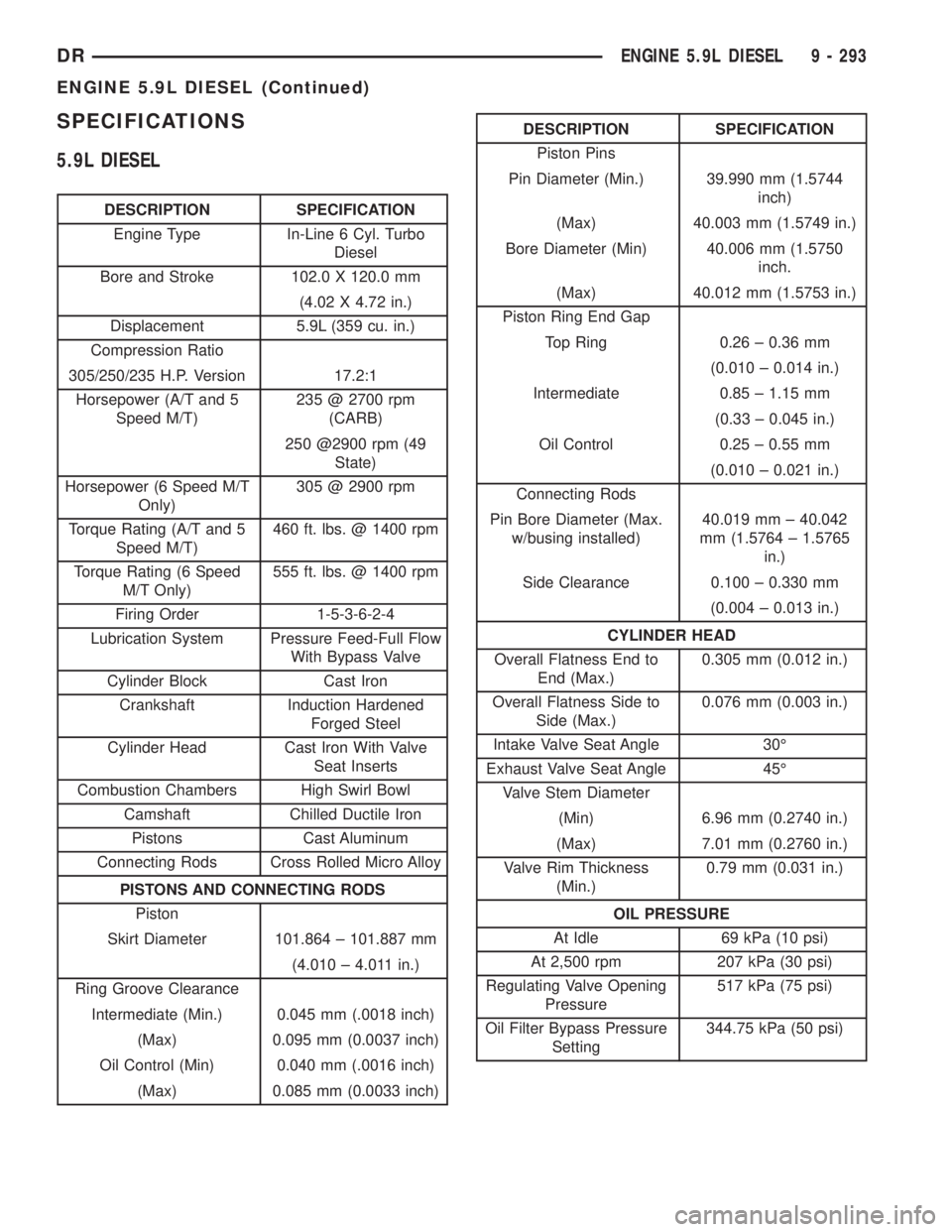
SPECIFICATIONS
5.9L DIESEL
DESCRIPTION SPECIFICATION
Engine Type In-Line 6 Cyl. Turbo
Diesel
Bore and Stroke 102.0 X 120.0 mm
(4.02 X 4.72 in.)
Displacement 5.9L (359 cu. in.)
Compression Ratio
305/250/235 H.P. Version 17.2:1
Horsepower (A/T and 5
Speed M/T)235 @ 2700 rpm
(CARB)
250 @2900 rpm (49
State)
Horsepower (6 Speed M/T
Only)305 @ 2900 rpm
Torque Rating (A/T and 5
Speed M/T)460 ft. lbs. @ 1400 rpm
Torque Rating (6 Speed
M/T Only)555 ft. lbs. @ 1400 rpm
Firing Order 1-5-3-6-2-4
Lubrication System Pressure Feed-Full Flow
With Bypass Valve
Cylinder Block Cast Iron
Crankshaft Induction Hardened
Forged Steel
Cylinder Head Cast Iron With Valve
Seat Inserts
Combustion Chambers High Swirl Bowl
Camshaft Chilled Ductile Iron
Pistons Cast Aluminum
Connecting Rods Cross Rolled Micro Alloy
PISTONS AND CONNECTING RODS
Piston
Skirt Diameter 101.864 ± 101.887 mm
(4.010 ± 4.011 in.)
Ring Groove Clearance
Intermediate (Min.) 0.045 mm (.0018 inch)
(Max) 0.095 mm (0.0037 inch)
Oil Control (Min) 0.040 mm (.0016 inch)
(Max) 0.085 mm (0.0033 inch)
DESCRIPTION SPECIFICATION
Piston Pins
Pin Diameter (Min.) 39.990 mm (1.5744
inch)
(Max) 40.003 mm (1.5749 in.)
Bore Diameter (Min) 40.006 mm (1.5750
inch.
(Max) 40.012 mm (1.5753 in.)
Piston Ring End Gap
Top Ring 0.26 ± 0.36 mm
(0.010 ± 0.014 in.)
Intermediate 0.85 ± 1.15 mm
(0.33 ± 0.045 in.)
Oil Control 0.25 ± 0.55 mm
(0.010 ± 0.021 in.)
Connecting Rods
Pin Bore Diameter (Max.
w/busing installed)40.019 mm ± 40.042
mm (1.5764 ± 1.5765
in.)
Side Clearance 0.100 ± 0.330 mm
(0.004 ± 0.013 in.)
CYLINDER HEAD
Overall Flatness End to
End (Max.)0.305 mm (0.012 in.)
Overall Flatness Side to
Side (Max.)0.076 mm (0.003 in.)
Intake Valve Seat Angle 30É
Exhaust Valve Seat Angle 45É
Valve Stem Diameter
(Min) 6.96 mm (0.2740 in.)
(Max) 7.01 mm (0.2760 in.)
Valve Rim Thickness
(Min.)0.79 mm (0.031 in.)
OIL PRESSURE
At Idle 69 kPa (10 psi)
At 2,500 rpm 207 kPa (30 psi)
Regulating Valve Opening
Pressure517 kPa (75 psi)
Oil Filter Bypass Pressure
Setting344.75 kPa (50 psi)
DRENGINE 5.9L DIESEL 9 - 293
ENGINE 5.9L DIESEL (Continued)
Page 1615 of 2895
DESCRIPTION SPECIFICATION
HYDRAULIC TAPPETS
Body Diameter 22.949 ± 22.962 mm
(0.9035 ± 0.9040 in.)
Clearance (to bore) 0.0203 ± 0.0610 mm
(0.0008 ± 0.0024 in.)
Dry Lash 1.524 ± 5.334 mm
(0.060 ± 0.210 in.)
Push Rod Length 195.52 ± 196.02 mm
(7.698 ± 7.717 in.)
OIL PRESSURE
Curb Idle (Min.*) 83 kPa (12 psi)
@ 3000 rpm 345 ± 414 kPa (50 ± 60
psi)
* If oil pressure is zero at curb idle, DO NOT RUN
ENGINE.
OIL PUMP
Clearance over Rotors
(Max.)0.1906 mm (0.0075 in.)
Cover Out of Flat (Max.) 0.051 mm (0.002 in.)
Inner Rotor Thickness
(Min.)14.925 ± 14.950 mm
(0.5876 ± 0.5886 in.)
Outer Rotor
Clearance (Max.) 0.1626 mm (0.006 in.)
Diameter (Min.) 82.461 mm (3.246 in.)
Thickness (Min.) 14.925 mm (0.5876 in.)
Tip Clearance between
Rotors
(Max.) 0.584 mm (0.0230 in.)
PISTONS
Clearance at Top of Skirt 0.013 ± 0.038 mm
(0.0005 ± 0.0015 in.)
Piston Length 82.5 mm (3.25 in.)
Piston Ring Groove
Depth
#1&2 91.30 ± 91.55 mm
(3.594 ± 3.604 in.)
#3 92.90 ± 93.15 mmDESCRIPTION SPECIFICATION
(3.657 ± 3.667 in.)
Weight 463 ± 473 grams (16.33
± 16.68 oz.)
Piston to Bore Clearance 0.013 ± 0.038 mm
(0.0005 ± 0.0015 in.)
Service Limit 0.0762 mm (0.003 in.)
PISTON PINS
Clearance in Piston 0.010 ± 0.020 mm
(0.0004 ± 0.0008 in.)
Diameter 24.996 ± 25.001 mm
(0.9841 ± 0.9843 in.)
End Play NONE
Length 67.8 ± 68.3 mm
(2.67 ± 2.69 in.)
PISTON RINGS
Ring Gap
Compression Rings 0.254 ± 0.508 mm
(0.010 ± 0.020 in.)
Oil Control (Steel Rails) 0.381 ± 1.397 mm
(0.015 ± 0.055 in.)
Ring Side Clearance
Compression Rings 0.074 ± 0.097 mm
(0.0029 ± 0.0038 in.)
Oil Ring (Steel Rails) 2.591 ± 2.743 mm
(0.102 ± 0.108 in.)
VALVE TIMING
Exhaust Valve
Closes (ATDC) 25É
Opens (BBDC) 60É
Duration 265É
Intake Valve
Closes (ATDC) 61É
Opens (BBDC) 6É
Duration 246É
Valve Overlap 31É
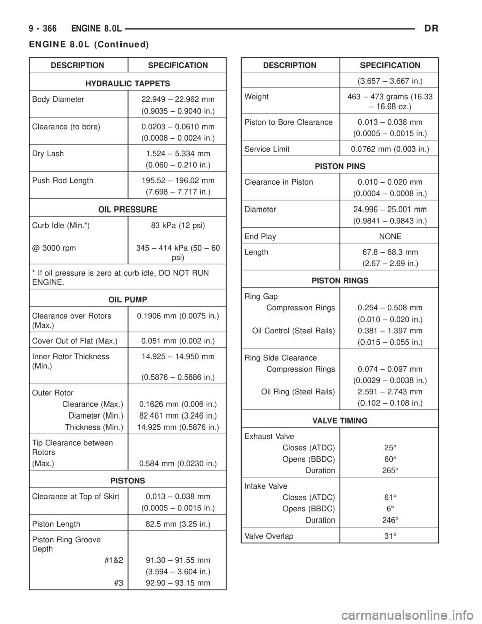
9 - 366 ENGINE 8.0LDR
ENGINE 8.0L (Continued)
Page 1620 of 2895
²Possible indications of the cylinder head gasket
leaking between a cylinder and an adjacent water
jacket are:
þ Engine overheating
þ Loss of coolant
þ Excessive steam (white smoke) emitting from
exhaust
þ Coolant foaming
CYLINDER-TO-CYLINDER LEAKAGE TEST
To determine if an engine cylinder head gasket is
leaking between adjacent cylinders, follow the proce-
dures in Cylinder Compression Pressure Test in this
section. An engine cylinder head gasket leaking
between adjacent cylinders will result in approxi-
mately a 50±70% reduction in compression pressure.
CYLINDER-TO-WATER JACKET LEAKAGE TEST
WARNING: USE EXTREME CAUTION WHEN THE
ENGINE IS OPERATING WITH COOLANT PRES-
SURE CAP REMOVED.
VISUAL TEST METHOD
With the engine cool, remove the coolant pressure
cap. Start the engine and allow it to warm up until
thermostat opens.
If a large combustion/compression pressure leak
exists, bubbles will be visible in the coolant.COOLING SYSTEM TESTER METHOD
WARNING: WITH COOLING SYSTEM TESTER IN
PLACE, PRESSURE WILL BUILD UP FAST. EXCES-
SIVE PRESSURE BUILT UP, BY CONTINUOUS
ENGINE OPERATION, MUST BE RELEASED TO A
SAFE PRESSURE POINT. NEVER PERMIT PRES-
SURE TO EXCEED 138 kPa (20 psi).
Install Cooling System Tester 7700 or equivalent to
pressure cap neck. Start the engine and observe the
tester's pressure gauge. If gauge pulsates with every
power stroke of a cylinder a combustion pressure
leak is evident.
CHEMICAL TEST METHOD
Combustion leaks into the cooling system can also
be checked by using Bloc-Chek Kit C-3685-A or
equivalent. Perform test following the procedures
supplied with the tool kit.
REMOVAL
(1) Disconnect the negative cable from the battery.
(2) Drain cooling system (Refer to 7 - COOLING -
STANDARD PROCEDURE).
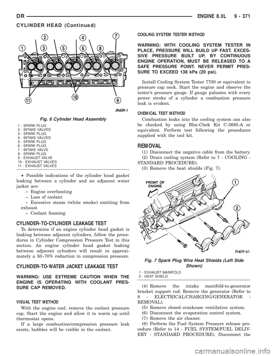
(3) Remove the heat shields (Fig. 7).
(4) Remove the intake manifold-to-generator
bracket support rod. Remove the generator (Refer to
8 - ELECTRICAL/CHARGING/GENERATOR -
REMOVAL).
(5) Remove closed crankcase ventilation system.
(6) Disconnect the evaporation control system.
(7) Remove the air cleaner.
(8) Perform the Fuel System Pressure release pro-
cedure (Refer to 14 - FUEL SYSTEM/FUEL DELIV-
ERY - STANDARD PROCEDURE). Disconnect the
Fig. 6 Cylinder Head Assembly
1 - SPARK PLUG
2 - INTAKE VALVES
3 - SPARK PLUG
4 - INTAKE VALVES
5 - SPARK PLUG
6 - SPARK PLUG
7 - INTAKE VALVE
8 - SPARK PLUG
9 - EXHAUST VALVE
10 - EXHAUST VALVES
11 - EXHAUST VALVES
Fig. 7 Spark Plug Wire Heat Shields (Left Side
Shown)
1 - EXHAUST MANIFOLD
2 - HEAT SHIELD
DRENGINE 8.0L 9 - 371
CYLINDER HEAD (Continued)
Page 1638 of 2895
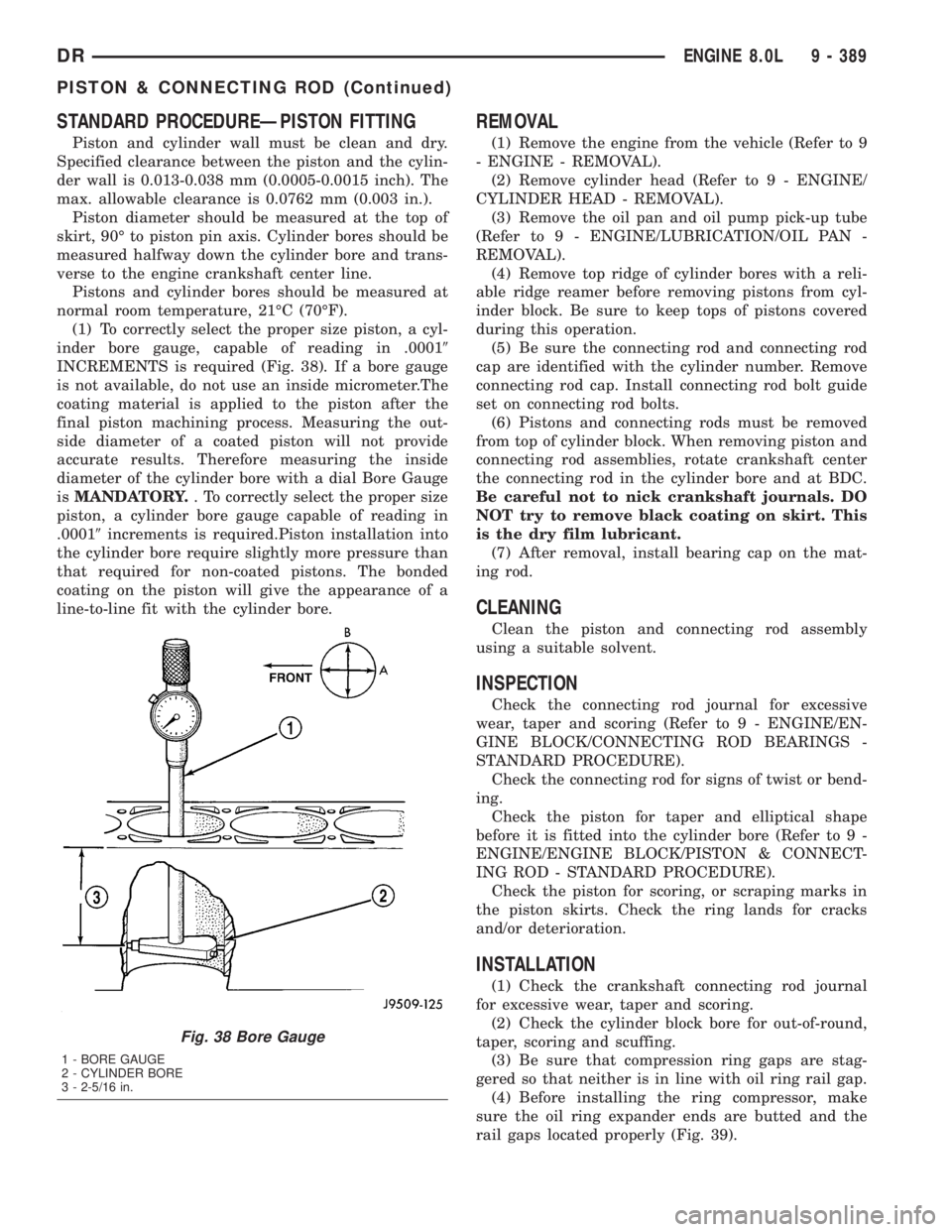
STANDARD PROCEDUREÐPISTON FITTING
Piston and cylinder wall must be clean and dry.
Specified clearance between the piston and the cylin-
der wall is 0.013-0.038 mm (0.0005-0.0015 inch). The
max. allowable clearance is 0.0762 mm (0.003 in.).
Piston diameter should be measured at the top of
skirt, 90É to piston pin axis. Cylinder bores should be
measured halfway down the cylinder bore and trans-
verse to the engine crankshaft center line.
Pistons and cylinder bores should be measured at
normal room temperature, 21ÉC (70ÉF).
(1) To correctly select the proper size piston, a cyl-
inder bore gauge, capable of reading in .00019
INCREMENTS is required (Fig. 38). If a bore gauge
is not available, do not use an inside micrometer.The
coating material is applied to the piston after the
final piston machining process. Measuring the out-
side diameter of a coated piston will not provide
accurate results. Therefore measuring the inside
diameter of the cylinder bore with a dial Bore Gauge
isMANDATORY.. To correctly select the proper size
piston, a cylinder bore gauge capable of reading in
.00019increments is required.Piston installation into
the cylinder bore require slightly more pressure than
that required for non-coated pistons. The bonded
coating on the piston will give the appearance of a
line-to-line fit with the cylinder bore.
REMOVAL
(1) Remove the engine from the vehicle (Refer to 9
- ENGINE - REMOVAL).
(2) Remove cylinder head (Refer to 9 - ENGINE/
CYLINDER HEAD - REMOVAL).
(3) Remove the oil pan and oil pump pick-up tube
(Refer to 9 - ENGINE/LUBRICATION/OIL PAN -
REMOVAL).
(4) Remove top ridge of cylinder bores with a reli-
able ridge reamer before removing pistons from cyl-
inder block. Be sure to keep tops of pistons covered
during this operation.
(5) Be sure the connecting rod and connecting rod
cap are identified with the cylinder number. Remove
connecting rod cap. Install connecting rod bolt guide
set on connecting rod bolts.
(6) Pistons and connecting rods must be removed
from top of cylinder block. When removing piston and
connecting rod assemblies, rotate crankshaft center
the connecting rod in the cylinder bore and at BDC.
Be careful not to nick crankshaft journals. DO
NOT try to remove black coating on skirt. This
is the dry film lubricant.
(7) After removal, install bearing cap on the mat-
ing rod.
CLEANING
Clean the piston and connecting rod assembly
using a suitable solvent.
INSPECTION
Check the connecting rod journal for excessive
wear, taper and scoring (Refer to 9 - ENGINE/EN-
GINE BLOCK/CONNECTING ROD BEARINGS -
STANDARD PROCEDURE).
Check the connecting rod for signs of twist or bend-
ing.
Check the piston for taper and elliptical shape
before it is fitted into the cylinder bore (Refer to 9 -
ENGINE/ENGINE BLOCK/PISTON & CONNECT-
ING ROD - STANDARD PROCEDURE).
Check the piston for scoring, or scraping marks in
the piston skirts. Check the ring lands for cracks
and/or deterioration.
INSTALLATION
(1) Check the crankshaft connecting rod journal
for excessive wear, taper and scoring.
(2) Check the cylinder block bore for out-of-round,
taper, scoring and scuffing.
(3) Be sure that compression ring gaps are stag-
gered so that neither is in line with oil ring rail gap.
(4) Before installing the ring compressor, make
sure the oil ring expander ends are butted and the
rail gaps located properly (Fig. 39).
Fig. 38 Bore Gauge
1 - BORE GAUGE
2 - CYLINDER BORE
3 - 2-5/16 in.
DRENGINE 8.0L 9 - 389
PISTON & CONNECTING ROD (Continued)
Page 1666 of 2895
(1) Loosen clamps holding air inlet duct rubber
sleeve to the intake manifold and air inlet duct.
Remove rubber sleeve (Fig. 13).
(2) Position Special Tool 8462 onto air inlet duct
and intake manifold. Using the existing clamps
tighten to 8 N´m (72 in. lbs.).
(3) Install the 3447.5 kPa 500 psi (gray) Pressure
Transducer (part of OT-CH8520 Transducer Kit) into
Special Tool 8462.
(4) Connect the DRB IIItto the pressure trans-
ducer following the instructions supplied with the
DRB IIIt.
(5) Enter DRB IIItinto pressure reading mode
and test drive vehicle.
(6) Full laod boost pressure at rated speed will be
158 - 186 kPa (23 - 27 psi.) depending on engine hp
rating.. If pressure readings are are not within this
range inspect for the following:
²Restricted air inlet system
²Leak in the charge air cooler system (Refer to 11
- EXHAUST SYSTEM/TURBOCHARGER SYSTEM/
CHARGE AIR COOLER AND PLUMBING - DIAG-
NOSIS AND TESTING)
²Turbocharger wastegate broken or misadjusted
²Restricted/high pressure drop across charge air
cooler²Turbocharger damaged (Refer to 11 - EXHAUST
SYSTEM/TURBOCHARGER SYSTEM/TURBO-
CHARGER - INSPECTION)
TURBOCHARGER
DESCRIPTION
The turbocharger is an exhaust-driven supercharger
which increases the pressure and density of the air
entering the engine. With the increase of air entering
the engine, more fuel can be injected into the cylin-
ders, which creates more power during combustion.
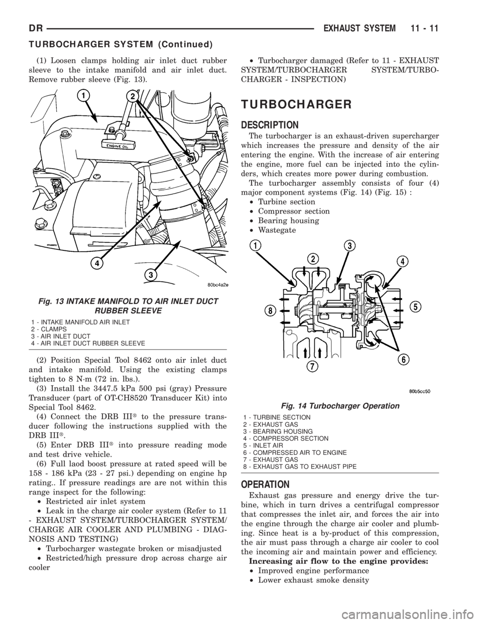
The turbocharger assembly consists of four (4)
major component systems (Fig. 14) (Fig. 15) :
²Turbine section
²Compressor section
²Bearing housing
²Wastegate
OPERATION
Exhaust gas pressure and energy drive the tur-
bine, which in turn drives a centrifugal compressor
that compresses the inlet air, and forces the air into
the engine through the charge air cooler and plumb-
ing. Since heat is a by-product of this compression,
the air must pass through a charge air cooler to cool
the incoming air and maintain power and efficiency.
Increasing air flow to the engine provides:
²Improved engine performance
²Lower exhaust smoke density
Fig. 13 INTAKE MANIFOLD TO AIR INLET DUCT
RUBBER SLEEVE
1 - INTAKE MANIFOLD AIR INLET
2 - CLAMPS
3 - AIR INLET DUCT
4 - AIR INLET DUCT RUBBER SLEEVE
Fig. 14 Turbocharger Operation
1 - TURBINE SECTION
2 - EXHAUST GAS
3 - BEARING HOUSING
4 - COMPRESSOR SECTION
5 - INLET AIR
6 - COMPRESSED AIR TO ENGINE
7 - EXHAUST GAS
8 - EXHAUST GAS TO EXHAUST PIPE
DREXHAUST SYSTEM 11 - 11
TURBOCHARGER SYSTEM (Continued)
Page 2076 of 2895
(7) Install thrust bearing in overdrive unit sliding
hub. Use petroleum jelly to hold bearing in position.
CAUTION: Be sure the shoulder on the inside diam-
eter of the bearing is facing forward.
(8) Verify that splines in overdrive planetary gear
and overrunning clutch hub are aligned with Align-
ment Tool 6227-2. Overdrive unit cannot be installed
if splines are not aligned. If splines have rotated out
of alignment, unit will have to be disassembled to
realign splines.
(9) Carefully slide Alignment Tool 6227-2 out of
overdrive planetary gear and overrunning clutch
splines.
(10) Raise overdrive unit and carefully slide it
straight onto intermediate shaft. Insert park rod into
park lock reaction plug at same time. Avoid tilting
overdrive during installation as this could cause
planetary gear and overrunning clutch splines torotate out of alignment. If this occurs, it will be nec-
essary to remove and disassemble overdrive unit to
realign splines.
(11) Work overdrive unit forward on intermediate
shaft until seated against transmission case.
(12) Install bolts attaching overdrive unit to trans-
mission unit. Tighten bolts in diagonal pattern to 34
N´m (25 ft-lbs).
(13) Connect the transmission speed sensor and
overdrive wiring connectors.
(14) Install the transfer case, if equipped.
(15) Align and install rear propeller shaft, if nec-
essary. (Refer to 3 - DIFFERENTIAL & DRIVELINE/
PROPELLER SHAFT/PROPELLER SHAFT -
INSTALLATION)
OVERRUNNING CLUTCH
CAM/OVERDRIVE PISTON
RETAINER
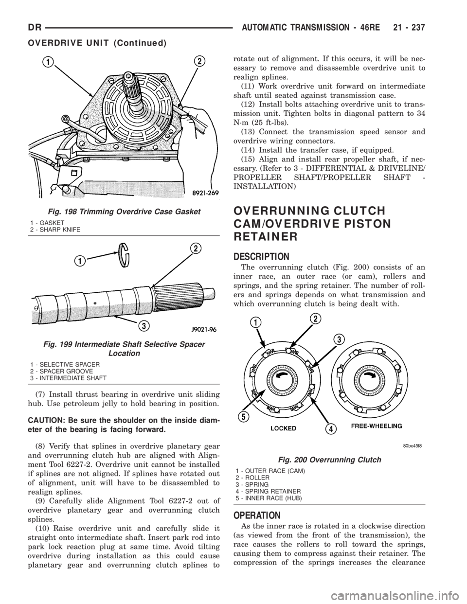
DESCRIPTION
The overrunning clutch (Fig. 200) consists of an
inner race, an outer race (or cam), rollers and
springs, and the spring retainer. The number of roll-
ers and springs depends on what transmission and
which overrunning clutch is being dealt with.
OPERATION
As the inner race is rotated in a clockwise direction
(as viewed from the front of the transmission), the
race causes the rollers to roll toward the springs,
causing them to compress against their retainer. The
compression of the springs increases the clearance
Fig. 198 Trimming Overdrive Case Gasket
1 - GASKET
2 - SHARP KNIFE
Fig. 199 Intermediate Shaft Selective Spacer
Location
1 - SELECTIVE SPACER
2 - SPACER GROOVE
3 - INTERMEDIATE SHAFT
Fig. 200 Overrunning Clutch
1 - OUTER RACE (CAM)
2 - ROLLER
3 - SPRING
4 - SPRING RETAINER
5 - INNER RACE (HUB)
DRAUTOMATIC TRANSMISSION - 46RE 21 - 237
OVERDRIVE UNIT (Continued)
Page 2254 of 2895
ment Tool 6227-2. Overdrive unit cannot be installed
if splines are not aligned. If splines have rotated out
of alignment, unit will have to be disassembled to
realign splines.
(9)
Carefully slide Alignment Tool 6227-2 out of over-
drive planetary gear and overrunning clutch splines.
(10) Raise overdrive unit and carefully slide it
straight onto intermediate shaft. Insert park rod into
park lock reaction plug at same time. Avoid tilting
overdrive during installation as this could cause
planetary gear and overrunning clutch splines to
rotate out of alignment. If this occurs, it will be nec-
essary to remove and disassemble overdrive unit to
realign splines.
(11) Work overdrive unit forward on intermediate
shaft until seated against transmission case.
(12) Install bolts attaching overdrive unit to trans-
mission unit. Tighten bolts in diagonal pattern to 34
N´m (25 ft-lbs).
(13) Connect the transmission speed sensor and
overdrive wiring connectors.
(14) Install the transfer case, if equipped.
(15) Align and install rear propeller shaft, if nec-
essary. (Refer to 3 - DIFFERENTIAL & DRIVELINE/
PROPELLER SHAFT/PROPELLER SHAFT -
INSTALLATION)
OVERRUNNING CLUTCH
CAM/OVERDRIVE PISTON
RETAINER
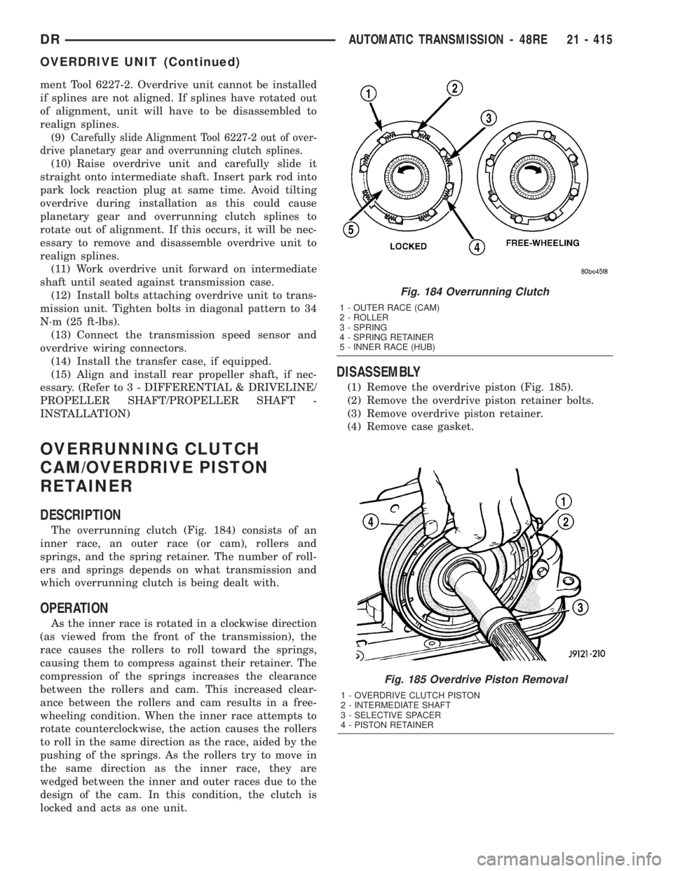
DESCRIPTION
The overrunning clutch (Fig. 184) consists of an
inner race, an outer race (or cam), rollers and
springs, and the spring retainer. The number of roll-
ers and springs depends on what transmission and
which overrunning clutch is being dealt with.
OPERATION
As the inner race is rotated in a clockwise direction
(as viewed from the front of the transmission), the
race causes the rollers to roll toward the springs,
causing them to compress against their retainer. The
compression of the springs increases the clearance
between the rollers and cam. This increased clear-
ance between the rollers and cam results in a free-
wheeling condition. When the inner race attempts to
rotate counterclockwise, the action causes the rollers
to roll in the same direction as the race, aided by the
pushing of the springs. As the rollers try to move in
the same direction as the inner race, they are
wedged between the inner and outer races due to the
design of the cam. In this condition, the clutch is
locked and acts as one unit.
DISASSEMBLY
(1) Remove the overdrive piston (Fig. 185).
(2) Remove the overdrive piston retainer bolts.
(3) Remove overdrive piston retainer.
(4) Remove case gasket.
Fig. 185 Overdrive Piston Removal
1 - OVERDRIVE CLUTCH PISTON
2 - INTERMEDIATE SHAFT
3 - SELECTIVE SPACER
4 - PISTON RETAINER
Fig. 184 Overrunning Clutch
1 - OUTER RACE (CAM)
2 - ROLLER
3 - SPRING
4 - SPRING RETAINER
5 - INNER RACE (HUB)
DRAUTOMATIC TRANSMISSION - 48RE 21 - 415
OVERDRIVE UNIT (Continued)