2003 DODGE RAM steering
[x] Cancel search: steeringPage 709 of 2895

DESCRIPTION - CIRCUIT FUNCTIONS
All circuits in the diagrams use an alpha/numeric
code to identify the wire and it's function. To identify
which circuit code applies to a system, refer to the
Circuit Identification Code Chart. This chart shows
the main circuits only and does not show the second-
ary codes that may apply to some models.
CIRCUIT IDENTIFICATION CODE CHART
CIRCUIT FUNCTION
A BATTERY FEED
B BRAKE CONTROLS
C CLIMATE CONTROLS
D DIAGNOSTIC CIRCUITS
E DIMMING ILLUMINATION
CIRCUITS
F FUSED CIRCUITS
G MONITORING CIRCUITS
(GAUGES)
H OPEN
I NOT USED
J OPEN
K POWERTRAIN CONTROL
MODULE
L EXTERIOR LIGHTING
M INTERIOR LIGHTING
N NOT USED
O NOT USED
P POWER OPTION (BATTERY
FEED)
Q POWER OPTIONS (IGNITION
FEED)
R PASSIVE RESTRAINT
S SUSPENSION/STEERING
T TRANSMISSION/TRANSAXLE/
TRANSFER CASE
U OPEN
V SPEED CONTROL, WIPER/
WASHER
W OPEN
X AUDIO SYSTEMS
Y OPEN
Z GROUNDS
DESCRIPTION - SECTION IDENTIFICATION AND
INFORMATION
The wiring diagrams are grouped into individual
sections. If a component is most likely found in a par-
ticular group, it will be shown complete (all wires,
connectors, and pins) within that group. For exam-
ple, the Auto Shutdown Relay is most likely to be
found in Group 30, so it is shown there complete. It
can, however, be shown partially in another group if
it contains some associated wiring.
Splice diagrams in Section 8W-70 show the entire
splice and provide references to other sections the
splices serves. Section 8W-70 only contains splice dia-
grams that are not shown in their entirety some-
where else in the wiring diagrams.
Section 8W-80 shows each connector and the cir-
cuits involved with that connector. The connectors
are identified using the name/number on the dia-
gram pages.
WIRING SECTION CHART
GROUP TOPIC
8W-01 thru
8W-09General information and Diagram
Overview
8W-10 thru
8W-19Main Sources of Power and
Vehicle Grounding
8W-20 thru
8W-29Starting and Charging
8W-30 thru
8W-39Powertrain/Drivetrain Systems
8W-40 thru
8W-49Body Electrical items and A/C
8W-50 thru
8W-59Exterior Lighting, Wipers and
Trailer Tow
8W-60 thru
8W-69Power Accessories
8W-70 Splice Information
8W-80 Connector Pin Outs
8W-91 Connector, Ground and Splice
Locations
8W - 01 - 6 8W-01 WIRING DIAGRAM INFORMATIONDR
WIRING DIAGRAM INFORMATION (Continued)
Page 721 of 2895

Component Page
Overdrive Switch...................... 8W-31
Overhead Map/Reading Lamp............ 8W-44
Oxygen Sensors....................... 8W-30
Oxygen Sensor Downstream Relay........ 8W-30
Park Brake Switch.................... 8W-40
Park Lamp Relay................... 8W-50, 52
Park/Turn Signal Lamps............. 8W-50, 52
Passenger Airbag On/Off Switch.......... 8W-43
Blend Door Actuators.................. 8W-42
Passenger Lumbar Switch............... 8W-63
Power Mirrors........................ 8W-62
Power Outlet......................... 8W-41
Power Outlet-Console.................. 8W-41
Power Seat Motors.................... 8W-63
Power Seat Switches................... 8W-63
Power Steering Pressure Switch.......... 8W-30
Power Window Circuit Breaker........... 8W-10
Power Window Motors.................. 8W-60
Power Window Switches................ 8W-60
Powertrain Control Module.............. 8W-30
PTCs............................... 8W-10
PTO Switch.......................... 8W-30
Radio............................... 8W-47
Recirculation Door Actuator............. 8W-42
Red Brake Warning Indicator Switch . . . 8W-34, 35
Remote Radio Switches................. 8W-47
Splices.............................. 8W-70
Seat Belt Pretensioners................. 8W-43
Seat Belt Switch-Driver................ 8W-40
Seat Belt Tensioner Reducer............. 8W-40
Seat Heater Interface Module............ 8W-63
Sentry Key Immobilizer Module.......... 8W-39
Spare Relay.......................... 8W-10
Speakers............................ 8W-47Component Page
Speed Control Servo................... 8W-33
Speed Control Switches................. 8W-33
Starter Motor Relay................... 8W-21
Starter Motor.................... 8W-21, 21-3
Tail/Stop Lamps...................... 8W-52
Tail/Stop/Turn Signal Lamps.......... 8W-51, 52
Tail/Turn Lamps...................... 8W-52
Tailgate Lamp Assembly................ 8W-51
Throttle Position Sensor................ 8W-30
Throttle Position Switch................ 8W-30
Trailer Tow Connector.................. 8W-54
Trailer Tow Connector-Add On........... 8W-54
Trailer Tow Left Turn Relay............. 8W-54
Trailer Tow Right Turn Relay............ 8W-54
Transfer Case Control Module............ 8W-31
Transfer Case Mode Sensor.............. 8W-31
Transfer Case Selector Switch............ 8W-31
Transfer Case Shift Motor............... 8W-31
Transmission Control Module............ 8W-31
Transmission Control Relay............. 8W-31
Transmission Range Sensor.............. 8W-31
Transmission Solenoid Assembly.......... 8W-31
Transmission Solenoid/TRS Assembly...... 8W-31
Underhood Lamp...................... 8W-44
Vacuum Pump........................ 8W-30
Vehicle Speed Sensor................... 8W-30
Vistronic Fan Drive.................... 8W-30
Washer Fluid Level Switch.............. 8W-53
Washer Pump Motor-Front.............. 8W-53
Water In Fuel Sensor.................. 8W-30
Wheel Speed Sensors................... 8W-35
Wiper High/Low Relay................. 8W-53
Wiper Motor-Front.................... 8W-53
8W - 02 - 2 8W-02 COMPONENT INDEXDR
Page 780 of 2895

8W-15 GROUND DISTRIBUTION
Component Page
A/C Compressor Clutch..................8W-15-9, 11
A/C-Heater Control....................8W-15-15, 17
Adjustable Pedal Switch...................8W-15-17
Airbag Control Module....................8W-15-18
Airbag Control Module-Left Side Impact.........8W-15-18
Airbag Control Module-Right Side Impact........8W-15-18
Amplifier Audio........................8W-15-14
Automatic Day/Night Mirror................8W-15-15
Auxiliary Battery........................8W-15-7
Battery..............................8W-15-7
Brake Lamp Switch......................8W-15-13
Brake Transmission Shift Interlock Solenoid.......8W-15-14
Center High Mounted Stop Lamp/Cargo Lamp.....8W-15-15
Cigar Lighter Outlet.....................8W-15-17
Clearance Lamp No. 1....................8W-15-16
Clearance Lamp No. 2....................8W-15-16
Clearance Lamp No. 3....................8W-15-16
Clearance Lamp No. 4....................8W-15-16
Clearance Lamp No. 5....................8W-15-16
Clockspring...........................8W-15-12
Clutch Interlock Brake Switch..............8W-15-2, 5
Compass/Mini-Trip Computer................8W-15-15
Condenser Fan........................8W-15-4, 6
Controller Antilock Brake...................8W-15-4
Cylinder Lock Switch-Driver................8W-15-19
Cylinder Lock Switch-Passenger..............8W-15-19
Data Link Connector.....................8W-15-13
Data Link Connector-Engine................8W-15-11
Door Ajar Switch-Driver...................8W-15-19
Door Ajar Switch-Left Rear.................8W-15-20
Door Ajar Switch-Passenger.................8W-15-19
Door Ajar Switch-Right Rear................8W-15-20
Door Lock Motor/Ajar Switch-Driver............8W-15-19
Door Lock Motor/Ajar Switch-Left Rear..........8W-15-20
Door Lock Motor/Ajar Switch-Passenger.........8W-15-19
Door Lock Motor/Ajar Switch-Right Rear.........8W-15-20
Door Lock Switch-Passenger.................8W-15-19
Driver Door Module......................8W-15-21
Electric Brake Provision..................8W-15-4, 6
Engine Control Module....................8W-15-11
Fender Lamp-Front Left....................8W-15-3
Fender Lamp-Front Right...................8W-15-3
Fender Lamp-Rear Left....................8W-15-3
Fender Lamp-Rear Right...................8W-15-3
Fog Lamp-Left........................8W-15-2, 5
Fog Lamp-Right.......................8W-15-2, 5
Fuel Heater...........................8W-15-11
Fuel Pump Module....................8W-15-3, 4, 6
G100................................8W-15-7
G101................................8W-15-7
G102................................8W-15-7
G103................................8W-15-2
G104..............................8W-15-5, 6
G105................................8W-15-7
G106................................8W-15-4
G107............................8W-15-8, 9, 10
G108................................8W-15-7
G109................................8W-15-7
G114 ...............................8W-15-11
G117 ...............................8W-15-11
Component Page
G120...............................8W-15-11
G201.............................8W-15-12, 13
G202.............................8W-15-14, 15
G203...............................8W-15-17
G204...............................8W-15-18
G301...............................8W-15-20
G302...............................8W-15-22
Generator..........................8W-15-10, 11
Headlamp Switch.......................8W-15-12
Headlamp-Left........................8W-15-2, 5
Headlamp-Right.........................8W-15-7
Heated Seat Cushion-Driver.................8W-15-22
Heated Seat Cushion-Passenger..............8W-15-22
Heated Seat Switch-Driver.................8W-15-13
Heated Seat Switch-Passenger...............8W-15-13
Horn-High Note.......................8W-15-4, 6
Horn-Low Note........................8W-15-4, 6
Ignition Switch.........................8W-15-12
Instrument Cluster....................8W-15-12, 14
Intake Air Heater Relay No. 1................8W-15-7
Intake Air Heater Relay No. 2................8W-15-7
Integrated Power Module..............8W-15-2, 4, 5, 8
Leak Detection Pump.....................8W-15-10
License Lamp-Left.......................8W-15-3
License Lamp-Right......................8W-15-3
Lift Pump Motor........................8W-15-11
Overdrive Switch.......................8W-15-13
Oxygen Sensor 1/1 Upstream................8W-15-10
Oxygen Sensor 1/2 Downstream.............8W-15-9, 10
Oxygen Sensor 2/1 Upstream................8W-15-10
Oxygen Sensor 2/2 Downstream.............8W-15-9, 10
Park/Turn Signal Lamp-Left Front............8W-15-2, 6
Park/Turn Signal Lamp-Right Front............8W-15-7
Power Mirror-Left.......................8W-15-21
Power Mirror-Right......................8W-15-22
Power Outlet..........................8W-15-17
Power Outlet-Console.....................8W-15-21
Power Seat Switch-Driver..................8W-15-21
Power Seat Switch-Passenger................8W-15-21
Power Steering Pressure Switch...............8W-15-9
Powertrain Control Module.............8W-15-8, 10, 11
Radio...............................8W-15-15
Red Brake Warning Indicator Switch..........8W-15-2, 6
Seat Belt Switch-Driver...................8W-15-20
Seat Heater Interface Module................8W-15-22
Sentry Key Immobilizer Module..............8W-15-12
Speed Control Servo.....................8W-15-2, 5
Tail/Stop/Turn Signal Lamp-Left...............8W-15-3
Tail/Stop/Turn Signal Lamp-Right..............8W-15-3
Tailgate Lamp Assembly....................8W-15-3
Trailer Tow Connector..................8W-15-3, 4, 6
Trailer Tow Connector-Add On.............8W-15-3, 4, 6
Transfer Case Control Module...............8W-15-17
Transfer Case Selector Switch................8W-15-13
Transmission Control Module.................8W-15-8
Underhood Lamp.......................8W-15-2, 6
Vacuum Pump..........................8W-15-7
Washer Pump Motor-Front.................8W-15-4, 7
Wiper Motor-Front....................8W-15-2, 4, 5
DR8W-15 GROUND DISTRIBUTION 8W - 15 - 1
Page 816 of 2895

8W-30 FUEL/IGNITION SYSTEM
Component PageA/C Compressor Clutch Relay...........8W-30-27, 36, 83
A/C Pressure Transducer.......8W-30-19, 20, 21, 48, 53, 70
Accelerator Pedal Position Sensor.............8W-30-55
Adjustable Pedal Motor....................8W-30-87
Adjustable Pedal Relay....................8W-30-87
Adjustable Pedal Switch...................8W-30-87
Ambient Temperature Sensor................8W-30-56
Auto Shut Down Relay..................8W-30-4, 31
Battery..............................8W-30-77
Battery Temperature Sensor............8W-30-28, 39, 81
Brake Lamp Switch.............8W-30-25, 35, 65, 82, 89
Camshaft Position Sensor.......8W-30-17, 18, 37, 55, 70, 71
Capacitor.........................8W-30-6, 11, 43
Clockspring..................8W-30-25, 35, 65, 84, 90
Clutch Interlock Brake Switch...............8W-30-32
Coil On Plug No. 1...................8W-30-8, 42, 61
Coil On Plug No. 2...................8W-30-7, 40, 60
Coil On Plug No. 3...................8W-30-8, 42, 61
Coil On Plug No. 4...................8W-30-7, 40, 60
Coil On Plug No. 5...................8W-30-6, 41, 61
Coil On Plug No. 6...................8W-30-6, 43, 60
Coil On Plug No. 7....................8W-30-41, 61
Coil On Plug No. 8....................8W-30-43, 60
Condenser Fan Relay...................8W-30-27, 36
Controller Antilock Brake...........8W-30-23, 33, 38, 82
Crankshaft Position Sensor.............8W-30-17, 18, 37
Data Link Connector..........8W-30-27, 36, 46, 80, 89, 91
Data Link Connector-Engine................8W-30-75
Electronic Throttle Control Module............8W-30-63
Engine Control Module......8W-30-67, 68, 69, 70, 71, 72, 73,
74, 75, 76, 77, 78, 79, 80, 81, 82,
83, 84, 90, 91
Engine Coolant Temperature
Sensor.................8W-30-19, 20, 21, 48, 64, 72
Engine Oil Pressure Switch......8W-30-19, 20, 21, 29, 78, 81
EVAP/Purge Solenoid...................8W-30-28, 39
Front Control Module.....................8W-30-87
Fuel Heater...........................8W-30-85
Fuel Heater Relay.......................8W-30-85
Fuel Injector No. 1...............8W-30-8, 9, 11, 42, 62
Fuel Injector No. 2...............8W-30-7, 9, 12, 40, 59
Fuel Injector No. 3...............8W-30-8, 9, 11, 42, 62
Fuel Injector No. 4...............8W-30-7, 9, 12, 40, 60
Fuel Injector No. 5...............8W-30-6, 9, 11, 41, 62
Fuel Injector No. 6...............8W-30-6, 9, 12, 43, 59
Fuel Injector No. 7................8W-30-9, 11, 41, 62
Fuel Injector No. 8................8W-30-9, 12, 43, 59
Fuel Injector No. 9.......................8W-30-11
Fuel Injector No. 10......................8W-30-12
Fuel Injector Pack No. 1...................8W-30-67
Fuel Injector Pack No. 2..............8W-30-67, 68, 69
Fuel Injector Pack No. 3...................8W-30-69
Fuel Pump Module................8W-30-3, 30, 79, 83
Fuel Pump Motor.......................8W-30-76
Fuel Pump Relay......................8W-30-3, 30
Fuel Rail Pressure Sensor..................8W-30-74
Fuse 2.............................8W-30-4, 31
Fuse 5............................8W-30-50, 88
Fuse 12.............................8W-30-85
Fuse 17............................8W-30-3, 30
Fuse 19.......................8W-30-2, 29, 77, 90
Fuse 36...........................8W-30-79, 87
Fuse 40.............................8W-30-87
Fuse 49............................8W-30-4, 31
Fuse 50...........................8W-30-28, 88Component PageFusible Link..........................8W-30-77
G103.........................8W-30-3, 25, 30, 35
G104.........................8W-30-3, 25, 30, 35
G105.............................8W-30-81, 86
G106...............................8W-30-85
G107.........8W-30-2, 16, 24, 29, 34, 40, 42, 45, 47, 50, 54
G114 ...............................8W-30-78
G117 ...............................8W-30-91
G120.............................8W-30-75, 85
G201..........................8W-30-23, 33, 91
G203...............................8W-30-87
Generator.......................8W-30-24, 34, 75
Idle Air Control Motor..................8W-30-27, 36
Ignition Coil...........................8W-30-9
Ignition Coil-Left.......................8W-30-10
Ignition Coil-Right.......................8W-30-10
Ignition Switch....................8W-30-23, 33, 46
Inlet Air Temperature/Pressure Sensor..........8W-30-73
Input Speed Sensor......................8W-30-49
Intake Air Heater Relay No. 1...............8W-30-81
Intake Air Heater Relay No. 2...............8W-30-81
Intake Air Temperature Sensor......8W-30-19, 20, 21, 48, 64
Intake Air Temperature/Manifold Absolute Pressure
Sensor............................8W-30-74
Integrated Power Module . . 8W-30-2, 3, 4, 26, 27, 29, 30, 31, 36,
50, 77, 79, 80, 83, 85, 86, 87, 88, 90
Knock Sensor..........................8W-30-22
Knock Sensor-Left.......................8W-30-57
Knock Sensor-Right......................8W-30-57
Leak Detection Pump..................8W-30-24, 34
Lift Pump Motor........................8W-30-75
Line Pressure Sensor.....................8W-30-44
Manifold Absolute Pressure
Sensor.................8W-30-19, 20, 21, 48, 55, 64
Output Speed Sensor................8W-30-26, 49, 88
Overdrive Switch...................8W-30-23, 33, 91
Oxygen Sensor 1/1 Upstream.......8W-30-13, 14, 15, 47, 54
Oxygen Sensor 1/2 Downstream.....8W-30-13, 14, 16, 45, 54
Oxygen Sensor 2/1 Upstream..............8W-30-15, 47
Oxygen Sensor 2/2 Downstream............8W-30-16, 45
Oxygen Sensor Downstream Relay...........8W-30-4, 31
Power Steering Pressure Switch............8W-30-24, 34
Powertrain Control Module . . 8W-30-2, 3, 4, 5, 6, 7, 8, 9, 10, 11,
12, 13, 14, 15, 16 17, 18, 19, 20, 21, 22, 23, 24, 25, 27, 28, 29,
30, 31, 32, 33, 34, 35, 36, 37, 38, 39, 40, 41, 42, 43, 44, 45, 46,
47, 48, 49, 50, 51, 52, 53, 54, 55, 56, 57, 58, 59, 60, 61, 62, 63,
64, 65, 66, 77, 79, 82, 84, 85, 88, 89, 90, 91
PTCNo.1 ...........8W-30-2, 3, 27, 29, 30, 36, 80, 83, 86
PTO Switch.........................8W-30-23, 33
Speed Control Servo.................8W-30-25, 35, 89
Speed Control Switch-Left.............8W-30-65, 84, 90
Speed Control Switch-Right............8W-30-65, 84, 90
Starter Motor Relay......................8W-30-29
Throttle Position Sensor.................8W-30-22, 44
Throttle Position Switch...................8W-30-72
Transfer Case Control Module...............8W-30-65
Transmission Control Module.......8W-30-17, 23, 33, 38, 66
Transmission Control Relay............8W-30-26, 50, 88
Transmission Range Sensor..................8W-30-5
Transmission Solenoid Assembly.......8W-30-20, 21, 26, 88
Transmission Solenoid/TRS Assembly . . 8W-30-5, 32, 50, 51, 52
Vacuum Pump.........................8W-30-86
Vehicle Speed Sensor.....................8W-30-71
Vistronic Fan Drive......................8W-30-79
Water In Fuel Sensor...................8W-30-72, 76
DR8W-30 FUEL/IGNITION SYSTEM 8W - 30 - 1
Page 1070 of 2895

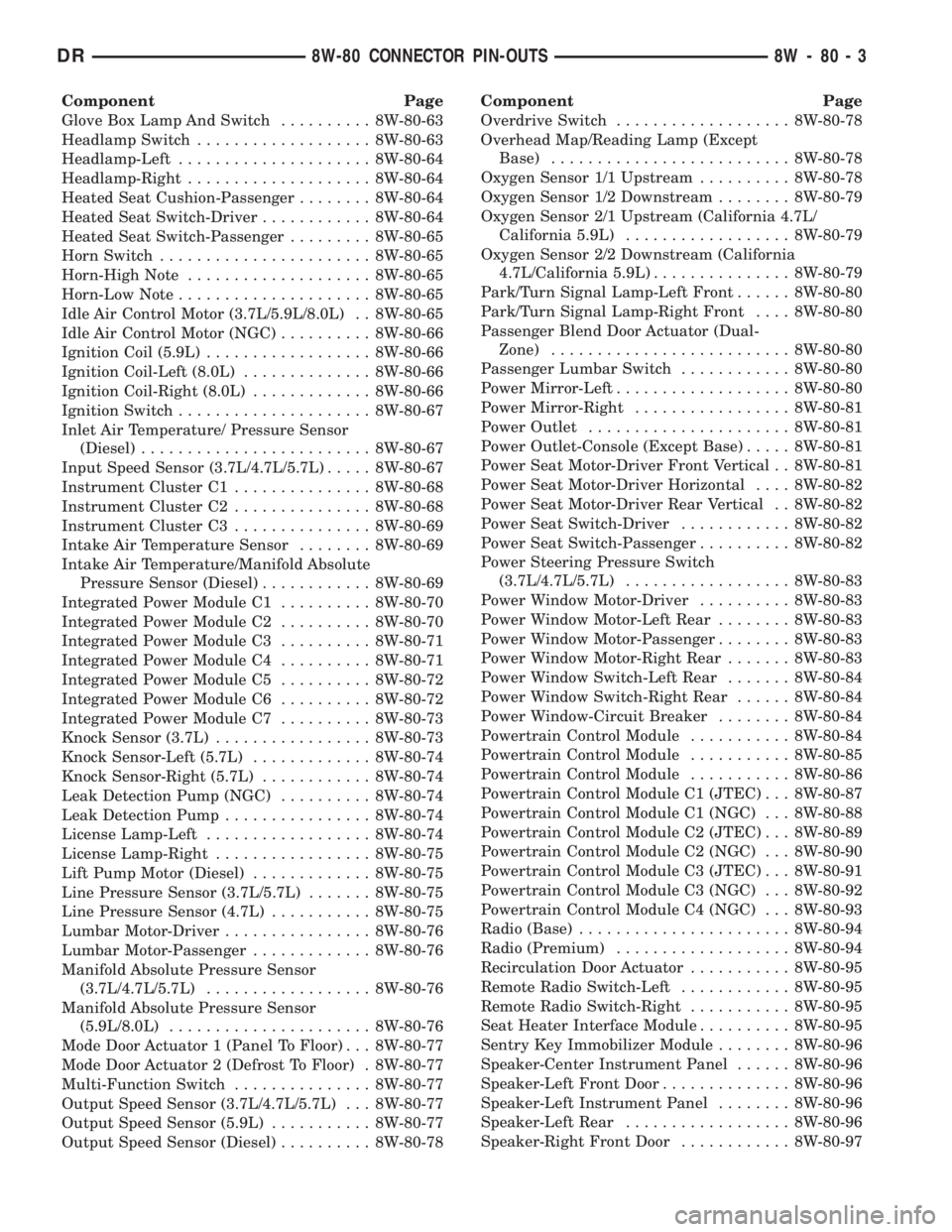
Component Page
Glove Box Lamp And Switch.......... 8W-80-63
Headlamp Switch................... 8W-80-63
Headlamp-Left..................... 8W-80-64
Headlamp-Right.................... 8W-80-64
Heated Seat Cushion-Passenger........ 8W-80-64
Heated Seat Switch-Driver............ 8W-80-64
Heated Seat Switch-Passenger......... 8W-80-65
Horn Switch....................... 8W-80-65
Horn-High Note.................... 8W-80-65
Horn-Low Note..................... 8W-80-65
Idle Air Control Motor (3.7L/5.9L/8.0L) . . 8W-80-65
Idle Air Control Motor (NGC).......... 8W-80-66
Ignition Coil (5.9L).................. 8W-80-66
Ignition Coil-Left (8.0L).............. 8W-80-66
Ignition Coil-Right (8.0L)............. 8W-80-66
Ignition Switch..................... 8W-80-67
Inlet Air Temperature/ Pressure Sensor
(Diesel)......................... 8W-80-67
Input Speed Sensor (3.7L/4.7L/5.7L)..... 8W-80-67
Instrument Cluster C1............... 8W-80-68
Instrument Cluster C2............... 8W-80-68
Instrument Cluster C3............... 8W-80-69
Intake Air Temperature Sensor........ 8W-80-69
Intake Air Temperature/Manifold Absolute
Pressure Sensor (Diesel)............ 8W-80-69
Integrated Power Module C1.......... 8W-80-70
Integrated Power Module C2.......... 8W-80-70
Integrated Power Module C3.......... 8W-80-71
Integrated Power Module C4.......... 8W-80-71
Integrated Power Module C5.......... 8W-80-72
Integrated Power Module C6.......... 8W-80-72
Integrated Power Module C7.......... 8W-80-73
Knock Sensor (3.7L)................. 8W-80-73
Knock Sensor-Left (5.7L)............. 8W-80-74
Knock Sensor-Right (5.7L)............ 8W-80-74
Leak Detection Pump (NGC).......... 8W-80-74
Leak Detection Pump................ 8W-80-74
License Lamp-Left.................. 8W-80-74
License Lamp-Right................. 8W-80-75
Lift Pump Motor (Diesel)............. 8W-80-75
Line Pressure Sensor (3.7L/5.7L)....... 8W-80-75
Line Pressure Sensor (4.7L)........... 8W-80-75
Lumbar Motor-Driver................ 8W-80-76
Lumbar Motor-Passenger............. 8W-80-76
Manifold Absolute Pressure Sensor
(3.7L/4.7L/5.7L).................. 8W-80-76
Manifold Absolute Pressure Sensor
(5.9L/8.0L)...................... 8W-80-76
Mode Door Actuator 1 (Panel To Floor) . . . 8W-80-77
Mode Door Actuator 2 (Defrost To Floor) . 8W-80-77
Multi-Function Switch............... 8W-80-77
Output Speed Sensor (3.7L/4.7L/5.7L) . . . 8W-80-77
Output Speed Sensor (5.9L)........... 8W-80-77
Output Speed Sensor (Diesel).......... 8W-80-78Component Page
Overdrive Switch................... 8W-80-78
Overhead Map/Reading Lamp (Except
Base).......................... 8W-80-78
Oxygen Sensor 1/1 Upstream.......... 8W-80-78
Oxygen Sensor 1/2 Downstream........ 8W-80-79
Oxygen Sensor 2/1 Upstream (California 4.7L/
California 5.9L).................. 8W-80-79
Oxygen Sensor 2/2 Downstream (California
4.7L/California 5.9L)............... 8W-80-79
Park/Turn Signal Lamp-Left Front...... 8W-80-80
Park/Turn Signal Lamp-Right Front.... 8W-80-80
Passenger Blend Door Actuator (Dual-
Zone).......................... 8W-80-80
Passenger Lumbar Switch............ 8W-80-80
Power Mirror-Left................... 8W-80-80
Power Mirror-Right................. 8W-80-81
Power Outlet...................... 8W-80-81
Power Outlet-Console (Except Base)..... 8W-80-81
Power Seat Motor-Driver Front Vertical . . 8W-80-81
Power Seat Motor-Driver Horizontal.... 8W-80-82
Power Seat Motor-Driver Rear Vertical . . 8W-80-82
Power Seat Switch-Driver............ 8W-80-82
Power Seat Switch-Passenger.......... 8W-80-82
Power Steering Pressure Switch
(3.7L/4.7L/5.7L).................. 8W-80-83
Power Window Motor-Driver.......... 8W-80-83
Power Window Motor-Left Rear........ 8W-80-83
Power Window Motor-Passenger........ 8W-80-83
Power Window Motor-Right Rear....... 8W-80-83
Power Window Switch-Left Rear....... 8W-80-84
Power Window Switch-Right Rear...... 8W-80-84
Power Window-Circuit Breaker........ 8W-80-84
Powertrain Control Module........... 8W-80-84
Powertrain Control Module........... 8W-80-85
Powertrain Control Module........... 8W-80-86
Powertrain Control Module C1 (JTEC) . . . 8W-80-87
Powertrain Control Module C1 (NGC) . . . 8W-80-88
Powertrain Control Module C2 (JTEC) . . . 8W-80-89
Powertrain Control Module C2 (NGC) . . . 8W-80-90
Powertrain Control Module C3 (JTEC) . . . 8W-80-91
Powertrain Control Module C3 (NGC) . . . 8W-80-92
Powertrain Control Module C4 (NGC) . . . 8W-80-93
Radio (Base)....................... 8W-80-94
Radio (Premium)................... 8W-80-94
Recirculation Door Actuator........... 8W-80-95
Remote Radio Switch-Left............ 8W-80-95
Remote Radio Switch-Right........... 8W-80-95
Seat Heater Interface Module.......... 8W-80-95
Sentry Key Immobilizer Module........ 8W-80-96
Speaker-Center Instrument Panel...... 8W-80-96
Speaker-Left Front Door.............. 8W-80-96
Speaker-Left Instrument Panel........ 8W-80-96
Speaker-Left Rear.................. 8W-80-96
Speaker-Right Front Door............ 8W-80-97
DR8W-80 CONNECTOR PIN-OUTS 8W - 80 - 3
Page 1150 of 2895

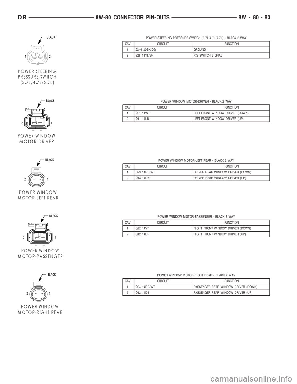
POWER STEERING PRESSURE SWITCH (3.7L/4.7L/5.7L) - BLACK 2 WAY
CAV CIRCUIT FUNCTION
1 Z244 20BK/DG GROUND
2 S28 18YL/BK P/S SWITCH SIGNAL
POWER WINDOW MOTOR-DRIVER - BLACK 2 WAY
CAV CIRCUIT FUNCTION
1 Q21 14WT LEFT FRONT WINDOW DRIVER (DOWN)
2 Q11 14LB LEFT FRONT WINDOW DRIVER (UP)
POWER WINDOW MOTOR-LEFT REAR - BLACK 2 WAY
CAV CIRCUIT FUNCTION
1 Q23 14RD/WT DRIVER REAR WINDOW DRIVER (DOWN)
2 Q13 14DB DRIVER REAR WINDOW DRIVER (UP)
POWER WINDOW MOTOR-PASSENGER - BLACK 2 WAY
CAV CIRCUIT FUNCTION
1 Q22 14VT RIGHT FRONT WINDOW DRIVER (DOWN)
2 Q12 14BR RIGHT FRONT WINDOW DRIVER (UP)
POWER WINDOW MOTOR-RIGHT REAR - BLACK 2 WAY
CAV CIRCUIT FUNCTION
1 Q24 14RD/WT PASSENGER REAR WINDOW DRIVER (DOWN)
2 Q12 14DB PASSENGER REAR WINDOW DRIVER (UP)
DR8W-80 CONNECTOR PIN-OUTS 8W - 80 - 83
Page 1154 of 2895

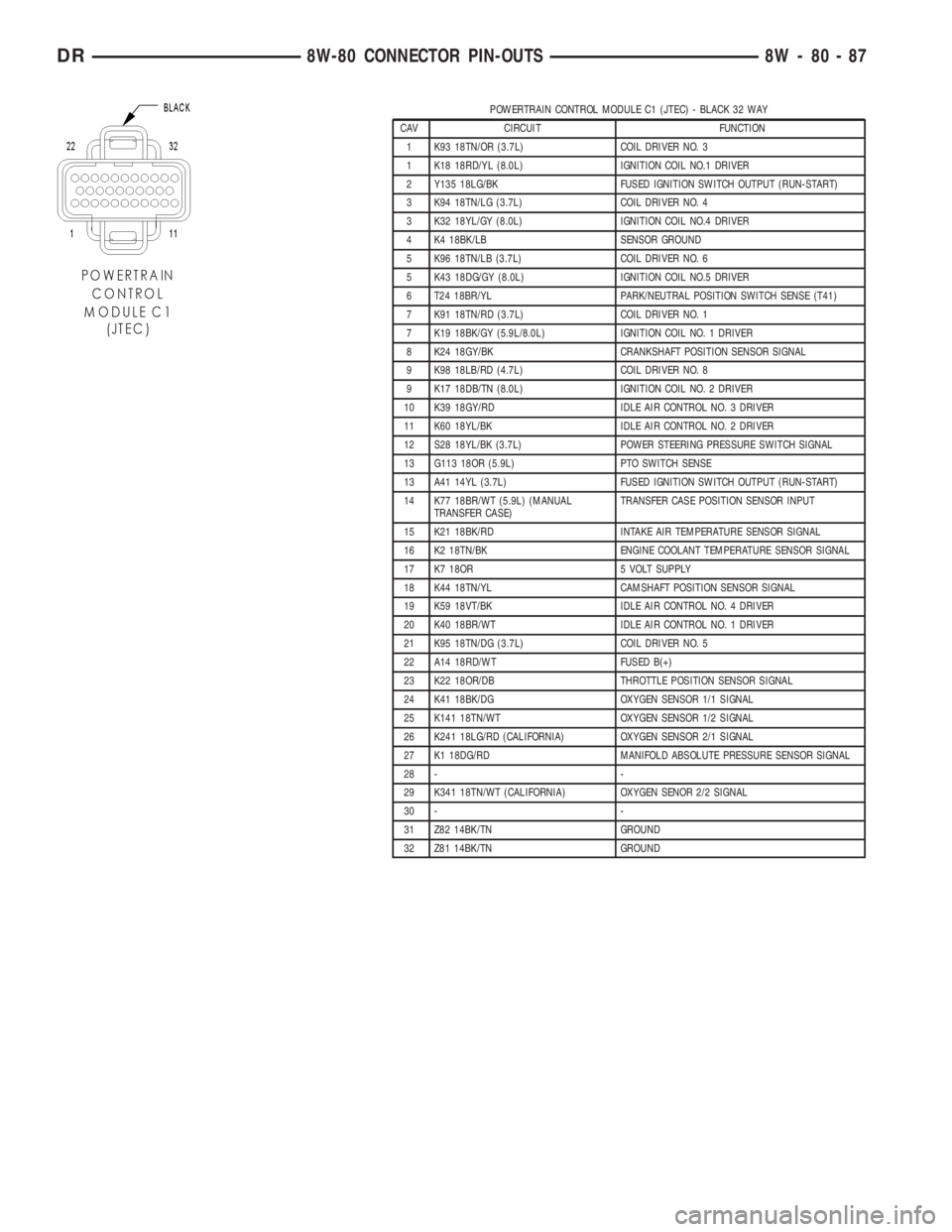
POWERTRAIN CONTROL MODULE C1 (JTEC) - BLACK 32 WAY
CAV CIRCUIT FUNCTION
1 K93 18TN/OR (3.7L) COIL DRIVER NO. 3
1 K18 18RD/YL (8.0L) IGNITION COIL NO.1 DRIVER
2 Y135 18LG/BK FUSED IGNITION SWITCH OUTPUT (RUN-START)
3 K94 18TN/LG (3.7L) COIL DRIVER NO. 4
3 K32 18YL/GY (8.0L) IGNITION COIL NO.4 DRIVER
4 K4 18BK/LB SENSOR GROUND
5 K96 18TN/LB (3.7L) COIL DRIVER NO. 6
5 K43 18DG/GY (8.0L) IGNITION COIL NO.5 DRIVER
6 T24 18BR/YL PARK/NEUTRAL POSITION SWITCH SENSE (T41)
7 K91 18TN/RD (3.7L) COIL DRIVER NO. 1
7 K19 18BK/GY (5.9L/8.0L) IGNITION COIL NO. 1 DRIVER
8 K24 18GY/BK CRANKSHAFT POSITION SENSOR SIGNAL
9 K98 18LB/RD (4.7L) COIL DRIVER NO. 8
9 K17 18DB/TN (8.0L) IGNITION COIL NO. 2 DRIVER
10 K39 18GY/RD IDLE AIR CONTROL NO. 3 DRIVER
11 K60 18YL/BK IDLE AIR CONTROL NO. 2 DRIVER
12 S28 18YL/BK (3.7L) POWER STEERING PRESSURE SWITCH SIGNAL
13 G113 18OR (5.9L) PTO SWITCH SENSE
13 A41 14YL (3.7L) FUSED IGNITION SWITCH OUTPUT (RUN-START)
14 K77 18BR/WT (5.9L) (MANUAL
TRANSFER CASE)TRANSFER CASE POSITION SENSOR INPUT
15 K21 18BK/RD INTAKE AIR TEMPERATURE SENSOR SIGNAL
16 K2 18TN/BK ENGINE COOLANT TEMPERATURE SENSOR SIGNAL
17 K7 18OR 5 VOLT SUPPLY
18 K44 18TN/YL CAMSHAFT POSITION SENSOR SIGNAL
19 K59 18VT/BK IDLE AIR CONTROL NO. 4 DRIVER
20 K40 18BR/WT IDLE AIR CONTROL NO. 1 DRIVER
21 K95 18TN/DG (3.7L) COIL DRIVER NO. 5
22 A14 18RD/WT FUSED B(+)
23 K22 18OR/DB THROTTLE POSITION SENSOR SIGNAL
24 K41 18BK/DG OXYGEN SENSOR 1/1 SIGNAL
25 K141 18TN/WT OXYGEN SENSOR 1/2 SIGNAL
26 K241 18LG/RD (CALIFORNIA) OXYGEN SENSOR 2/1 SIGNAL
27 K1 18DG/RD MANIFOLD ABSOLUTE PRESSURE SENSOR SIGNAL
28 - -
29 K341 18TN/WT (CALIFORNIA) OXYGEN SENOR 2/2 SIGNAL
30 - -
31 Z82 14BK/TN GROUND
32 Z81 14BK/TN GROUND
DR8W-80 CONNECTOR PIN-OUTS 8W - 80 - 87
Page 1178 of 2895

8W-91 CONNECTOR/GROUND/SPLICE LOCATION
TABLE OF CONTENTS
page
CONNECTOR/GROUND/SPLICE LOCATION
DESCRIPTION..........................1
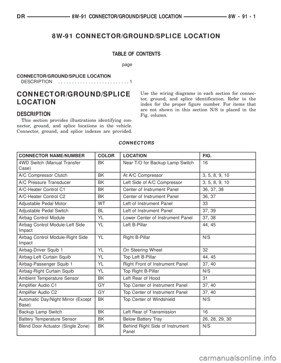
CONNECTOR/GROUND/SPLICE
LOCATION
DESCRIPTION
This section provides illustrations identifying con-
nector, ground, and splice locations in the vehicle.
Connector, ground, and splice indexes are provided.Use the wiring diagrams in each section for connec-
tor, ground, and splice identification. Refer to the
index for the proper figure number. For items that
are not shown in this section N/S is placed in the
Fig. column.
CONNECTORS
CONNECTOR NAME/NUMBER COLOR LOCATION FIG.
4WD Switch (Manual Transfer
Case)BK Near T/O for Backup Lamp Switch 16
A/C Compressor Clutch BK At A/C Compressor 3, 5, 8, 9, 10
A/C Pressure Transducer BK Left Side of A/C Compressor 3, 5, 8, 9, 10
A/C-Heater Control C1 BK Center of Instrument Panel 36, 37, 38
A/C-Heater Control C2 BK Center of Instrument Panel 36, 37
Adjustable Pedal Motor WT Left of Instrument Panel 33
Adjustable Pedal Switch BL Left of Instrument Panel 37, 39
Airbag Control Module YL Lower Center of Instrument Panel 37, 38
Airbag Control Module-Left Side
ImpactYL Left B-Pillar 44, 45
Airbag Control Module-Right Side
ImpactYL Right B-Pillar N/S
Airbag-Driver Squib 1 YL On Steering Wheel 32
Airbag-Left Curtain Squib YL Top Left B-Pillar 44, 45
Airbag-Passenger Squib 1 YL Right Front of Instrument Panel 37, 40
Airbag-Right Curtain Squib YL Top Right B-Pillar N/S
Ambient Temperature Sensor BK Left Rear of Hood 31
Amplifier Audio C1 GY Top Center of Instrument Panel 37, 40
Amplifier Audio C2 GY Top Center of Instrument Panel 37, 40
Automatic Day/Night Mirror (Except
Base)BK Top Center of Windshield N/S
Backup Lamp Switch BK Left Rear of Transmission 16
Battery Temperature Sensor BK Below Battery Tray 26, 28, 29, 30
Blend Door Actuator (Single Zone) BK Behind Right Side of Instrument
PanelN/S
DR8W-91 CONNECTOR/GROUND/SPLICE LOCATION 8W - 91 - 1