2003 DODGE RAM steering
[x] Cancel search: steeringPage 668 of 2895
REMOVAL
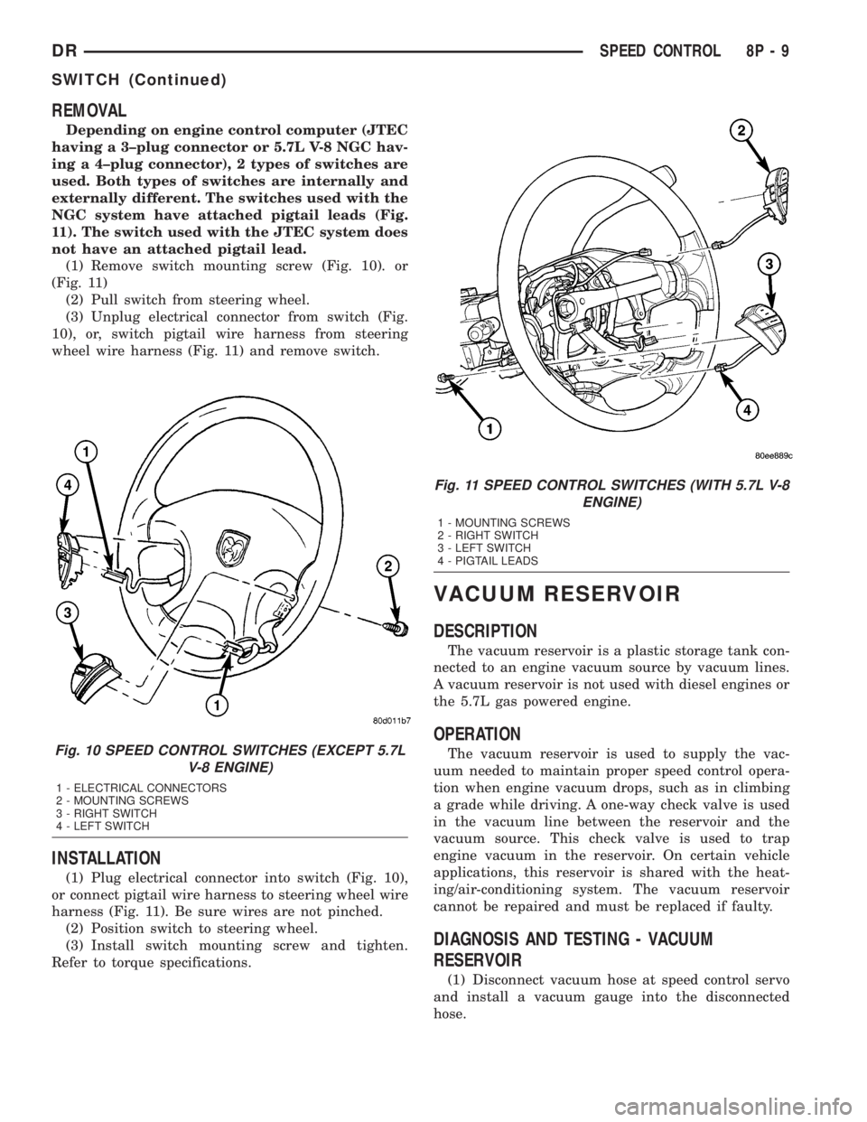
Depending on engine control computer (JTEC
having a 3±plug connector or 5.7L V-8 NGC hav-
ing a 4±plug connector), 2 types of switches are
used. Both types of switches are internally and
externally different. The switches used with the
NGC system have attached pigtail leads (Fig.
11). The switch used with the JTEC system does
not have an attached pigtail lead.
(1) Remove switch mounting screw (Fig. 10). or
(Fig. 11)
(2) Pull switch from steering wheel.
(3) Unplug electrical connector from switch (Fig.
10), or, switch pigtail wire harness from steering
wheel wire harness (Fig. 11) and remove switch.
INSTALLATION
(1) Plug electrical connector into switch (Fig. 10),
or connect pigtail wire harness to steering wheel wire
harness (Fig. 11). Be sure wires are not pinched.
(2) Position switch to steering wheel.
(3) Install switch mounting screw and tighten.
Refer to torque specifications.
VACUUM RESERVOIR
DESCRIPTION
The vacuum reservoir is a plastic storage tank con-
nected to an engine vacuum source by vacuum lines.
A vacuum reservoir is not used with diesel engines or
the 5.7L gas powered engine.
OPERATION
The vacuum reservoir is used to supply the vac-
uum needed to maintain proper speed control opera-
tion when engine vacuum drops, such as in climbing
a grade while driving. A one-way check valve is used
in the vacuum line between the reservoir and the
vacuum source. This check valve is used to trap
engine vacuum in the reservoir. On certain vehicle
applications, this reservoir is shared with the heat-
ing/air-conditioning system. The vacuum reservoir
cannot be repaired and must be replaced if faulty.
DIAGNOSIS AND TESTING - VACUUM
RESERVOIR
(1) Disconnect vacuum hose at speed control servo
and install a vacuum gauge into the disconnected
hose.
Fig. 10 SPEED CONTROL SWITCHES (EXCEPT 5.7L
V-8 ENGINE)
1 - ELECTRICAL CONNECTORS
2 - MOUNTING SCREWS
3 - RIGHT SWITCH
4 - LEFT SWITCH
Fig. 11 SPEED CONTROL SWITCHES (WITH 5.7L V-8
ENGINE)
1 - MOUNTING SCREWS
2 - RIGHT SWITCH
3 - LEFT SWITCH
4 - PIGTAIL LEADS
DRSPEED CONTROL 8P - 9
SWITCH (Continued)
Page 670 of 2895

VEHICLE THEFT SECURITY
TABLE OF CONTENTS
page page
VEHICLE THEFT SECURITY
DESCRIPTION
DESCRIPTION........................1
SENTRY KEY IMMOBILIZER SYSTEM (SKIS) . 1
DESCRIPTION........................1
OPERATION
OPERATION..........................2
OPERATION..........................2
OPERATION..........................2
DIAGNOSIS AND TESTING
VEHICLE THEFT SECURITY SYSTEM......3STANDARD PROCEDURE
CONFIGURING A NEW MODULE / SWITCH
OPERATING MODES....................3
SENTRY KEY IMMOBILIZER SYSTEM
INITIALIZATION........................3
SENTRY KEY IMMOBILIZER SYSTEM
TRANSPONDER PROGRAMMING..........4
SENTRY KEY IMMOBILIZER SYSTEM
INDICATOR LAMP
DESCRIPTION..........................5
OPERATION............................5
VEHICLE THEFT SECURITY
DESCRIPTION
DESCRIPTION
The Vehicle Theft/Security System (VTSS) is
designed to protect against whole vehicle theft. The
system monitors the vehicle doors and ignition for
unauthorized operation.
The VTSS activates:
²Sounding of the horn
²Flashing of the park lamps
²Flashing of the head lamps
The Remote Keyless Entry (RKE) has 1 mode of
operation,CUSTOMER USAGEmode. The cus-
tomer usage mode provides full functionality of the
module and is the mode in which the RKE module
should be operating when used by the customer.
SENTRY KEY IMMOBILIZER SYSTEM (SKIS)
The Sentry Key Immobilizer System (SKIS) is
designed to provide passive protection against unau-
thorized vehicle use by preventing the engine from
operating while the system is armed. The primary
components of this system are the Sentry Key Immo-
bilizer Module (SKIM), the Sentry Key transponder,
the Vehicle Theft/Security System (VTSS) indicator
LED, and the Powertrain Control Module (PCM).
The SKIM is installed on the steering column near
the ignition lock cylinder. The transponder is located
under the molded rubber cap on the head of the igni-tion key. The VTSS indicator LED is located in the
instrument cluster.
The SKIS includes two valid Sentry Key transpon-
ders from the factory. This is so the customer can self
program new keys if one is lost. If the customer
wishes, additional non-coded blank Sentry Keys are
available. These blank keys can be cut to match a
valid ignition key, but the engine will not start
unless the key transponder is also programmed to
the vehicle. The SKIS will recognize no more than
eight valid Sentry Key transponders at any one time.
The SKIS performs a self-test each time the igni-
tion switch is turned to the ON position, and will
store Diagnostic Trouble Codes (DTC's) if a system
malfunction is detected. The SKIS can be diagnosed,
and any stored DTC can be retrieved using a
DRBIIItscan tool as described in the proper Body
Diagnostic Procedures Manual.
DESCRIPTION
The Sentry Key Immobilizer Module (SKIM) con-
tains a Radio Frequency (RF) transceiver and a cen-
tral processing unit, which includes the Sentry Key
Immobilizer System (SKIS) program logic. The SKIS
programming enables the SKIM to program and
retain in memory the codes of at least two, but no
more than eight electronically coded Sentry Key
transponders. The SKIS programming also enables
the SKIM to communicate over the Programmable
Communication Interface (PCI) bus network with the
Powertrain Control Module (PCM), and/or the
DRBIIItscan tool.
DRVEHICLE THEFT SECURITY 8Q - 1
Page 671 of 2895

OPERATION
OPERATION
When in theCustomer Usagemode of operation,
the system is armed when the vehicle is locked using
the:
²Power Door Lock Switches
²Remote Keyless Entry (RKE) Transmitter
²Key Cylinder Switches
After the vehicle is locked and the last door is
closed, the VTSS indicator in the instrument cluster
will flash quickly for 16 seconds, indicating that the
arming is in process. After 16 seconds, the LED will
continue to flash at a slower rate indicating that the
system is armed.
VTSS disarming occurs upon normal vehicle entry
by unlocking either door via the key cylinder or RKE
transmitter, or by starting the vehicle with a valid
Sentry Key. This disarming will also halt the alarm
once it has been activated.
A tamper alert exists to notify the driver that the
system has been activated. This alert consists of 3
horn pulses and the security telltail flashing for 30
seconds when the vehicle is disarmed. The tamper
alert will not occur if disarmed while alarming.
The VTSS will not arm by mechanically locking the
vehicle doors. This will manually override the sys-
tem.
OPERATION
The SKIS includes two valid Sentry Key transpon-
ders from the factory. These two Sentry Keys can be
used to program additional non-coded blank Sentry
Keys. These blank keys can be cut to match a valid
ignition key, but the engine will not start unless the
key transponder is also programmed to the vehicle.
The SKIS will recognize no more than eight valid
Sentry Key transponders at any one time.
The SKIS performs a self-test each time the igni-
tion switch is turned to the ON position, and will
store Diagnostic Trouble Codes (DTC's) if a system
malfunction is detected. The SKIS can be diagnosed,
and any stored DTC can be retrieved using a
DRBIIItscan tool as described in the proper Power-
train Diagnostic Procedures manual.
OPERATION
The SKIM transmits and receives RF signals
through a tuned antenna enclosed within a molded
plastic ring formation that is integral to the SKIM
housing. When the SKIM is properly installed on the
steering column, the antenna ring is oriented around
the circumference of the ignition lock cylinder hous-
ing. This antenna ring must be located within eight
millimeters (0.31 inches) of the Sentry Key in orderto ensure proper RF communication between the
SKIM and the Sentry Key transponder.
For added system security, each SKIM is pro-
grammed with a unique ªSecret Keyº code and a
security code. The SKIM keeps the ªSecret Keyº code
in memory. The SKIM also sends the ªSecret Keyº
code to each of the programmed Sentry Key tran-
sponders. The security code is used by the assembly
plant to access the SKIS for initialization, or by the
dealer technician to access the system for service.
The SKIM also stores in its memory the Vehicle
Identification Number (VIN), which it learns through
a PCI bus message from the PCM during initializa-
tion.
The SKIM and the PCM both use software that
includes a rolling code algorithm strategy, which
helps to reduce the possibility of unauthorized SKIS
disarming. The rolling code algorithm ensures secu-
rity by preventing an override of the SKIS through
the unauthorized substitution of the SKIM or the
PCM. However, the use of this strategy also means
that replacement of either the SKIM or the PCM
units will require a system initialization procedure to
restore system operation.
When the ignition switch is turned to the ON or
START positions, the SKIM transmits an RF signal
to excite the Sentry Key transponder. The SKIM then
listens for a return RF signal from the transponder
of the Sentry Key that is inserted in the ignition lock
cylinder. If the SKIM receives an RF signal with
valid ªSecret Keyº and transponder identification
codes, the SKIM sends a ªvalid keyº message to the
PCM over the PCI bus. If the SKIM receives an
invalid RF signal or no response, it sends ªinvalid
keyº messages to the PCM. The PCM will enable or
disable engine operation based upon the status of the
SKIM messages.
The SKIM also sends messages to the Instrument
Cluster which controls the VTSS indicator. The
SKIM sends messages to the Instrument Cluster to
turn the indicator on for about three seconds when
the ignition switch is turned to the ON position as a
ªbulbº test. After completion of the ªbulbº test, the
SKIM sends bus messages to keep the indicator off
for a duration of about one second. Then the SKIM
sends messages to turn the indicator on or off based
upon the results of the SKIS self-tests. If the VTSS
indicator comes on and stays on after the ªbulb testº,
it indicates that the SKIM has detected a system
malfunction and/or that the SKIS has become inoper-
ative.
If the SKIM detects an invalid key when the igni-
tion switch is turned to the ON position, it sends
messages to flash the VTSS indicator. The SKIM can
also send messages to flash the indicator to serve as
an indication to the customer that the SKIS has been
8Q - 2 VEHICLE THEFT SECURITYDR
VEHICLE THEFT SECURITY (Continued)
Page 672 of 2895
placed in its ªCustomer Learnº programming mode.
See Sentry Key Immobilizer System Transponder
Programming in this section for more information on
the ªCustomer Learnº programming mode.
For diagnosis or initialization of the SKIM and the
PCM, a DRBIIItscan tool and the proper Powertrain
Diagnostic Procedures manual are required. The
SKIM cannot be repaired and, if faulty or damaged,
the unit must be replaced.
DIAGNOSIS AND TESTING
VEHICLE THEFT SECURITY SYSTEM
WARNING: ON VEHICLES EQUIPPED WITH AIR-
BAGS, REFER TO RESTRAINT SYSTEMS BEFORE
ATTEMPTING ANY STEERING WHEEL, STEERING
COLUMN, OR INSTRUMENT PANEL COMPONENT
DIAGNOSIS OR SERVICE. FAILURE TO TAKE THE
PROPER PRECAUTIONS COULD RESULT IN ACCI-
DENTAL AIRBAG DEPLOYMENT AND POSSIBLE
PERSONAL INJURY.
NOTE: The most reliable, efficient, and accurate
means to diagnose the Vehicle Theft Security Sys-
tem (VTSS) and Sentry Key Immobilizer System
(SKIS) involves the use of a DRBlllTscan tool and
the proper Powertrain Diagnostic Procedures man-
ual.
The Vehicle Theft Security System (VTSS), Sentry
Key Immobilizer System (SKIS) and the Programma-
ble Communication Interface (PCI) bus network
should be diagnosed using a DRBIIItscan tool. The
DRBIIItwill allow confirmation that the PCI bus is
functional, that the Sentry Key Immobilizer Module
(SKIM) is placing the proper messages on the PCI
bus, and that the Powertrain Control Module (PCM)
and the Instrument Cluster are receiving the PCI
bus messages. Refer to the proper Powertrain or
Body Diagnostic Procedures manual.
Visually inspect the related wiring harness connec-
tors. Look for broken, bent, pushed out or corroded
terminals. If any of the conditions are present, repair
as necessary. Refer to Wiring Diagrams for complete
circuit descriptions and diagrams. Refer to (Refer to
8 - ELECTRICAL/ELECTRONIC CONTROL MOD-
ULES/SENTRY KEY IMMOBILIZER MODULE -
REMOVAL) for SKIM replacement.
STANDARD PROCEDURE
CONFIGURING A NEW MODULE / SWITCH
OPERATING MODES
To configure a new module or to switch operating
modes, a DRBIIItscan tool must be used.
(1) Hook up the DRBIIItscan tool to the Data
Link Connector (DLC).
(2) With the key in the ignition, turn the key to
the RUN position.
(3) After the DRBIIItscan tool initialization, per-
form the following:
(a) Select ªTheft Alarm.º
(b) Select ªVTSS.º
(c) Select ªMiscellaneous.º
(4) Once in the ªMiscellaneousº screen:
(a) If you wish to configure a new module, select
ªConfigure Module.º
(b) If you wish to put the module into customer
usage mode, select ªEnable VTSS.º
(c) If you wish to put the module into dealer lot
mode, select ªDealer Lot.º
SENTRY KEY IMMOBILIZER SYSTEM
INITIALIZATION
The Sentry Key Immobilizer System (SKIS) initial-
ization should be performed following a Sentry Key
Immobilizer Module (SKIM) replacement.
It can be summarized by the following:
(1) Obtain the vehicles unique PIN number
assigned to it's original SKIM from the vehicle
owner, the vehicle's invoice or from Chrysler's Cus-
tomer Center.
(2) With the DRBIIItscan tool, select ªTheft
Alarm,º ªSKIM,º Miscellaneous.º Select ªSKIM Mod-
ule Replacedº function and the DRBIIItwill prompt
you through the following steps.
(3) Enter secured access mode using the unique
four digit PIN number.
(4) Program the vehicle's VIN number into the
SKIM's memory.
(5) Program the country code into the SKIM's
memory (U.S.).
(6) Transfer the vehicle's unique Secret Key data
from the PCM. This process will require the SKIM to
be insecured access mode. The PIN number must
be entered into the DRBIIItbefore the SKIM will
entersecured access mode. Oncesecured access
modeis active, the SKIM will remain in that mode
for 60 seconds.
(7) Program all customer keys into the SKIM's
memory. This required that the SKIM be insecured
access modeThe SKIM will immediately exit
secured access modeafter each key is pro-
grammed.
DRVEHICLE THEFT SECURITY 8Q - 3
VEHICLE THEFT SECURITY (Continued)
Page 677 of 2895
²Instrument Cluster- In this model, the instru-
ment cluster is also sometimes referred to as the Cab
Control Node (CCN). The instrument cluster is
located in the instrument panel above the steering
column opening, directly in front of the driver. (Refer
to 8 - ELECTRICAL/INSTRUMENT CLUSTER -
DESCRIPTION).
²Multi-Function Switch- The multi-function
switch is located on the top of the steering column,
just below the steering wheel. The multi-function
switch includes a control stalk that extends through
an opening on the left side of the steering column
shrouds and a control knob on the end of the stalk is
dedicated to providing all of the driver controls for
the wiper and washer systems. (Refer to 8 - ELEC-
TRICAL/LAMPS/LIGHTING - EXTERIOR/MULTI-
FUNCTION SWITCH - DESCRIPTION).²Washer Fluid Level Switch- The washer fluid
level switch is located in a dedicated hole on the out-
board side of the washer reservoir in the engine com-
partment.
²Washer Nozzle- Two fluidic washer nozzles are
secured with integral snap features to dedicated
openings in the cowl plenum cover/grille panel
located near the base of the windshield.
²Washer Plumbing- The plumbing for the
washer system consists of rubber hoses and molded
plastic fittings. The plumbing is routed along the
right side of the engine compartment from the
washer reservoir, and through a trough near the
right end of the cowl plenum cover/grille panel into
the cowl plenum to the washer nozzle fittings.
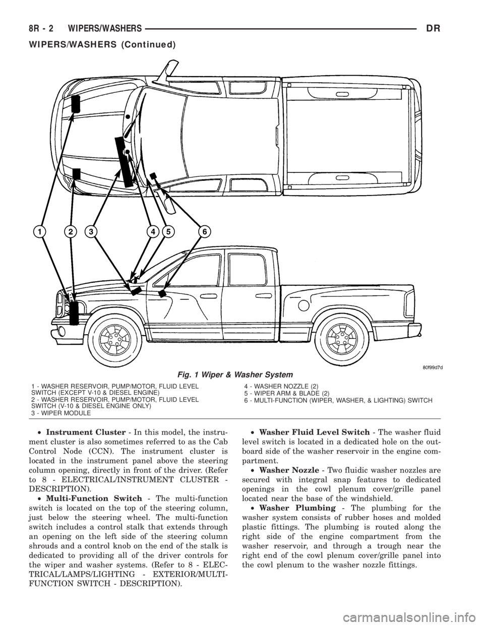
Fig. 1 Wiper & Washer System
1 - WASHER RESERVOIR, PUMP/MOTOR, FLUID LEVEL
SWITCH (EXCEPT V-10 & DIESEL ENGINE)
2 - WASHER RESERVOIR, PUMP/MOTOR, FLUID LEVEL
SWITCH (V-10 & DIESEL ENGINE ONLY)
3 - WIPER MODULE4 - WASHER NOZZLE (2)
5 - WIPER ARM & BLADE (2)
6 - MULTI-FUNCTION (WIPER, WASHER, & LIGHTING) SWITCH
8R - 2 WIPERS/WASHERSDR
WIPERS/WASHERS (Continued)
Page 679 of 2895
²Wipe-After-Wash Mode- When the control
knob on the control stalk of the multi-function switch
is depressed to the momentary Wash position for
more than about one-half second with the wiper sys-
tem turned Off, the washer pump/motor and the wip-
ers will operate for as long as the washer switch is
held closed up to about thirty seconds, then provide
several additional wipe cycles after the control knob
is released before parking the wiper blades near the
base of the windshield. If the control knob is held in
the depressed Wash position for more than about
thirty seconds, washer system operation will be sus-
pended until the control knob is released for about
two seconds then cycled back to the Wash position.
OPERATION
The wiper and washer system is designed to pro-
vide the vehicle operator with a convenient, safe, and
reliable means of maintaining visibility through the
windshield glass. The various components of this sys-
tem are designed to convert electrical energy pro-
duced by the vehicle electrical system into the
mechanical action of the wiper blades to wipe the
outside surface of the glass, as well as into the
hydraulic action of the washer system to apply
washer fluid stored in an on-board reservoir to the
area of the glass to be wiped. When combined, these
components provide the means to effectively main-
tain clear visibility for the vehicle operator by remov-
ing excess accumulations of rain, snow, bugs, mud, or
other minor debris from the outside windshield glass
surface that might be encountered while driving the
vehicle under numerous types of inclement operating
conditions.
The vehicle operator initiates all wiper and washer
system functions with the control knob on the end of
the control stalk of the multi-function switch that
extends from the left side of the steering column, just
below the steering wheel. Rotating the control knob
on the end of the control stalk, selects the Off, Delay,
Low, or High wiper system operating modes. In the
Delay mode, the control knob also allows the vehicle
operator to select from one of five intermittent wipe
Delay intervals. Depressing the control knob towards
the steering column actuates the momentary washer
system switch, which selects the Wash, Wipe-After-
Wash, and Pulse Wipe Modes depending upon when
and how long the switch is held closed. The multi-
function switch provides hard wired resistor multi-
plexed inputs to the instrument cluster for all of the
wiper and washer system functions. The instrument
cluster then sends electronic messages to the Front
Control Module (FCM) over the Programmable Com-
munications Interface (PCI) data bus requesting the
appropriate wiper and washer system operating
modes.Wiper and washer system operation are completely
controlled by the instrument cluster and FCM logic
circuits, and that logic will only allow these systems
to operate when the ignition switch is in the Acces-
sory or On positions. Battery current is directed from
a B(+) fuse in the Integrated Power Module (IPM) to
the wiper on/off relay and the wiper high/low relay in
the IPM through a fused B(+) circuit. The FCM uses
low side drivers to control wiper system operation by
energizing or de-energizing the wiper high/low and
wiper on/off relays. The FCM uses a high side driver
to control the operation of the washer pump motor
unit. The multi-function switch circuitry receives a
clean ground output from the instrument cluster on a
multi-function switch return circuit, then provides
resistor multiplexed inputs to the instrument cluster
on an intermittent wipe mux circuit to indicate the
selected wiper system mode and on a wash/beam
select mux circuit to indicate the selected washer sys-
tem mode.
The hard wired circuits and components of the
wiper and washer system may be diagnosed and
tested using conventional diagnostic tools and proce-
dures. However, conventional diagnostic methods
may not prove conclusive in the diagnosis of the
instrument cluster, the FCM, or the electronic mes-
sage inputs to or outputs from the instrument cluster
or FCM that control the wiper and washer system
operating modes. The most reliable, efficient, and
accurate means to diagnose the instrument cluster or
the FCM inputs and outputs related to the various
wiper and washer system operating modes requires
the use of a DRBIIItscan tool. Refer to the appro-
priate diagnostic information.
OPERATING MODES
Following are paragraphs that briefly describe the
operation of each of the wiper and washer system
operating modes.
CONTINUOUS WIPE MODE
When the Low position of the control knob on the
control stalk of the multi-function switch is selected
the instrument cluster sends an electronic wiper
switch low message to the FCM, then the FCM ener-
gizes the wiper on/off relay. This directs battery cur-
rent through the normally open contacts of the
energized wiper on/off relay and the normally closed
contacts of the de-energized wiper high/low relay to
the low speed brush of the wiper motor, causing the
wipers to cycle at low speed.
When the High position of the control knob is
selected the instrument cluster sends an electronic
wiper switch high message to the FCM, then the
FCM energizes both the wiper on/off relay and the
wiper high/low relay. This directs battery current
8R - 4 WIPERS/WASHERSDR
WIPERS/WASHERS (Continued)
Page 681 of 2895
If the control knob is held depressed for more than
about thirty seconds, the FCM will suspend washer
pump/motor operation until the knob is released for
about two seconds, then cycled back to the Wash
position; however, the wipers will continue to operate
for as long as the Wash switch is held closed. The
FCM monitors the changing state of the wiper motor
park switch through a hard wired wiper park switch
sense circuit input. This input allows the FCM to
count the number of wipe cycles that occur after the
Wash switch is released, and to determine the proper
interval at which to de-energize the wiper on/off
relay to complete the wipe-after-wash mode cycle.
DIAGNOSIS AND TESTING - WIPER &
WASHER SYSTEM
If the wiper motor operates, but the wipers do not
move on the windshield, replace the faulty wiper
module. If the washer pump/motor operates, but no
washer fluid is dispensed on the glass; or, if the wip-
ers operate, but chatter, lift, or do not clear the glass,
clean and inspect the wiper and washer system com-
ponents as required. (Refer to 8 - ELECTRICAL/
WIPERS/WASHERS - CLEANING) and (Refer to 8 -
ELECTRICAL/WIPERS/WASHERS - INSPECTION).
For diagnosis and testing of the multi-function
switch (Refer to 8 - ELECTRICAL/LAMPS/LIGHT-
ING - EXTERIOR/MULTI-FUNCTION SWITCH -
DIAGNOSIS AND TESTING). Refer to the appropri-
ate wiring information. The wiring information
includes wiring diagrams, proper wire and connector
repair procedures, details of wire harness routing
and retention, connector pin-out information and
location views for the various wire harness connec-
tors, splices and grounds.
The hard wired circuits and components of the
wiper and washer system may be diagnosed and
tested using conventional diagnostic tools and proce-
dures. However, conventional diagnostic methods
may not prove conclusive in the diagnosis of the
instrument cluster, the Front Control Module (FCM),
or the electronic message inputs to or outputs from
the instrument cluster and the FCM that control the
various wiper and washer system operating modes.
The most reliable, efficient, and accurate means to
diagnose the instrument cluster, the FCM, or the
electronic message inputs and outputs related to the
various wiper and washer system operating modes
requires the use of a DRBIIItscan tool. Refer to the
appropriate diagnostic information.
WARNING: ON VEHICLES EQUIPPED WITH AIR-
BAGS, DISABLE THE SUPPLEMENTAL RESTRAINT
SYSTEM BEFORE ATTEMPTING ANY STEERING
WHEEL, STEERING COLUMN, DRIVER AIRBAG,
PASSENGER AIRBAG, SEAT BELT TENSIONER,SIDE CURTAIN AIRBAG, OR INSTRUMENT PANEL
COMPONENT DIAGNOSIS OR SERVICE. DISCON-
NECT AND ISOLATE THE BATTERY NEGATIVE
(GROUND) CABLE, THEN WAIT TWO MINUTES FOR
THE SYSTEM CAPACITOR TO DISCHARGE BEFORE
PERFORMING FURTHER DIAGNOSIS OR SERVICE.
THIS IS THE ONLY SURE WAY TO DISABLE THE
SUPPLEMENTAL RESTRAINT SYSTEM. FAILURE TO
TAKE THE PROPER PRECAUTIONS COULD
RESULT IN ACCIDENTAL AIRBAG DEPLOYMENT
AND POSSIBLE PERSONAL INJURY.
CLEANING - WIPER & WASHER SYSTEM
WIPER SYSTEM
The squeegees of wiper blades exposed to the ele-
ments for a long time tend to lose their wiping effec-
tiveness. Periodic cleaning of the squeegees is
suggested to remove any deposits of salt or road film.
The wiper blades, arms, and windshield glass should
only be cleaned using a sponge or soft cloth and
windshield washer fluid, a mild detergent, or a non-
abrasive cleaner. If the wiper blades continue to
leave streaks, smears, hazing, or beading on the
glass after thorough cleaning of the squeegees and
the glass, the entire wiper blade assembly must be
replaced.
CAUTION: Protect the rubber squeegees of the
wiper blades from any petroleum-based cleaners,
solvents, or contaminants. These products can rap-
idly deteriorate the rubber squeegees.
WASHER SYSTEM
If the washer system is contaminated with foreign
material, drain the washer reservoir by removing the
washer pump/motor from the reservoir. Clean foreign
material from the inside of the washer pump/motor
inlet filter screen and the washer reservoir using
clean washer fluid, a mild detergent, or a non-abra-
sive cleaner. Flush foreign material from the washer
system plumbing by first disconnecting the washer
hoses from the washer nozzles, then running the
washer pump/motor to run clean washer fluid or
water through the system. Plugged or restricted
washer nozzles should be carefully back-flushed
using compressed air. If the washer nozzle obstruc-
tion cannot be cleared, replace the washer nozzle.
CAUTION: Never introduce petroleum-based clean-
ers, solvents, or contaminants into the washer sys-
tem. These products can rapidly deteriorate the
rubber seals and hoses of the washer system, as
well as the rubber squeegees of the wiper blades.
8R - 6 WIPERS/WASHERSDR
WIPERS/WASHERS (Continued)
Page 688 of 2895
(4) Reinstall the washer hose for the washer noz-
zle into its routing clips on the underside of the cowl
plenum cover/grille panel.
(5) Reinstall the cowl plenum cover/grille panel
over the cowl plenum. (Refer to 23 - BODY/EXTERI-
OR/COWL GRILLE - INSTALLATION).
(6) Close and latch the hood.
(7) Reinstall both wiper arms onto the wiper piv-
ots. (Refer to 8 - ELECTRICAL/WIPERS/WASHERS/
WIPER ARM - INSTALLATION).
WASHER PUMP/MOTOR
DESCRIPTION
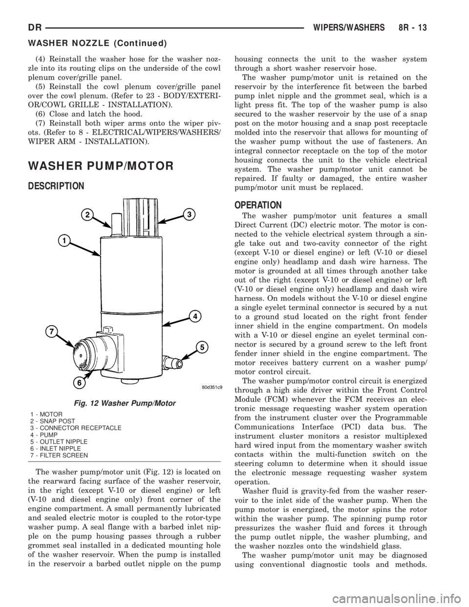
The washer pump/motor unit (Fig. 12) is located on
the rearward facing surface of the washer reservoir,
in the right (except V-10 or diesel engine) or left
(V-10 and diesel engine only) front corner of the
engine compartment. A small permanently lubricated
and sealed electric motor is coupled to the rotor-type
washer pump. A seal flange with a barbed inlet nip-
ple on the pump housing passes through a rubber
grommet seal installed in a dedicated mounting hole
of the washer reservoir. When the pump is installed
in the reservoir a barbed outlet nipple on the pumphousing connects the unit to the washer system
through a short washer reservoir hose.
The washer pump/motor unit is retained on the
reservoir by the interference fit between the barbed
pump inlet nipple and the grommet seal, which is a
light press fit. The top of the washer pump is also
secured to the washer reservoir by the use of a snap
post on the motor housing and a snap post receptacle
molded into the reservoir that allows for mounting of
the washer pump without the use of fasteners. An
integral connector receptacle on the top of the motor
housing connects the unit to the vehicle electrical
system. The washer pump/motor unit cannot be
repaired. If faulty or damaged, the entire washer
pump/motor unit must be replaced.
OPERATION
The washer pump/motor unit features a small
Direct Current (DC) electric motor. The motor is con-
nected to the vehicle electrical system through a sin-
gle take out and two-cavity connector of the right
(except V-10 or diesel engine) or left (V-10 or diesel
engine only) headlamp and dash wire harness. The
motor is grounded at all times through another take
out of the right (except V-10 or diesel engine) or left
(V-10 or diesel engine only) headlamp and dash wire
harness. On models without the V-10 or diesel engine
a single eyelet terminal connector is secured by a nut
to a ground stud located on the right front fender
inner shield in the engine compartment. On models
with a V-10 or diesel engine an eyelet terminal con-
nector is secured by a ground screw to the left front
fender inner shield in the engine compartment. The
motor receives battery current on a washer pump/
motor control circuit.
The washer pump/motor control circuit is energized
through a high side driver within the Front Control
Module (FCM) whenever the FCM receives an elec-
tronic message requesting washer system operation
from the instrument cluster over the Programmable
Communications Interface (PCI) data bus. The
instrument cluster monitors a resistor multiplexed
hard wired input from the momentary washer switch
contacts within the multi-function switch on the
steering column to determine when it should issue
the electronic message requesting washer system
operation.
Washer fluid is gravity-fed from the washer reser-
voir to the inlet side of the washer pump. When the
pump motor is energized, the motor spins the rotor
within the washer pump. The spinning pump rotor
pressurizes the washer fluid and forces it through
the pump outlet nipple, the washer plumbing, and
the washer nozzles onto the windshield glass.
The washer pump/motor unit may be diagnosed
using conventional diagnostic tools and methods.
Fig. 12 Washer Pump/Motor
1 - MOTOR
2 - SNAP POST
3 - CONNECTOR RECEPTACLE
4 - PUMP
5 - OUTLET NIPPLE
6 - INLET NIPPLE
7 - FILTER SCREEN
DRWIPERS/WASHERS 8R - 13
WASHER NOZZLE (Continued)