2003 DODGE RAM relay
[x] Cancel search: relayPage 1776 of 2895
FUEL INJECTION - DIESEL
TABLE OF CONTENTS
page page
ACCELERATOR PEDAL POSITION SENSOR
DESCRIPTION
DESCRIPTION (EARLY)................79
DESCRIPTION (LATE)..................79
OPERATION...........................79
REMOVAL.............................79
INSTALLATION.........................82
CAMSHAFT POSITION SENSOR
DESCRIPTION.........................82
OPERATION...........................82
REMOVAL.............................83
INSTALLATION.........................83
CRANKSHAFT POSITION SENSOR
DESCRIPTION.........................83
OPERATION...........................83
REMOVAL.............................84
INSTALLATION.........................84
FUEL CONTROL ACTUATOR
DESCRIPTION.........................85
OPERATION...........................85
REMOVAL.............................85
INSTALLATION.........................85
FUEL INJECTOR
DESCRIPTION.........................85
OPERATION...........................86
REMOVAL.............................87
INSTALLATION.........................87
FUEL INJECTOR RAIL
DESCRIPTION.........................89
OPERATION...........................89REMOVAL.............................89
INSTALLATION.........................90
INLET AIR TEMPERATURE SENSOR/
PRESSURE SENSOR
DESCRIPTION.........................90
OPERATION...........................90
REMOVAL.............................90
INSTALLATION.........................90
INTAKE AIR HEATER
DESCRIPTION.........................91
OPERATION...........................91
REMOVAL.............................91
INSTALLATION.........................91
INTAKE AIR HEATER RELAY
DESCRIPTION.........................92
OPERATION...........................92
REMOVAL.............................93
INSTALLATION.........................93
INTAKE AIR TEMPERATURE SENSOR/MAP
SENSOR
DESCRIPTION.........................93
OPERATION...........................93
REMOVAL.............................93
INSTALLATION.........................94
MAP SENSOR
DESCRIPTION.........................94
THROTTLE CONTROL CABLE
REMOVAL.............................94
INSTALLATION.........................96
ACCELERATOR PEDAL
POSITION SENSOR
DESCRIPTION
DESCRIPTION (EARLY)
The APPS assembly is located at the top-left-front
of the engine. A plastic cover is used to cover the
assembly. The actual sensor is located behind its
mounting bracket.
DESCRIPTION (LATE)
The Accelerator Pedal Position Sensor (APPS)
assembly is located under the vehicle battery tray. A
cable connects the assembly to the accelerator pedal.A plastic cover with a movable door is used to cover
the assembly.
OPERATION
The Accelerator Pedal Position Sensor (APPS) is a
linear potentiometer. It provides the Engine Control
Module (ECM) with a DC voltage signal proportional
to the angle, or position of the accelerator pedal.
REMOVAL
Early Diesel Engines
The APPS is serviced (replaced) as one assembly
including the lever, brackets and sensor. The APPS is
calibrated to its mounting bracket. The APPS assem-
bly is located at left-front of engine below plastic
cable/lever/linkage cover (Fig. 1).
DRFUEL INJECTION - DIESEL 14 - 79
Page 1788 of 2895
INTAKE AIR HEATER
DESCRIPTION
The intake manifold air heater element assembly
is located in the top of the intake manifold.
OPERATION
The air heater elements are used to heat incoming
air to the intake manifold. This is done to help
engine starting and improve driveability with cool or
cold outside temperatures.
Electrical supply for the 2 air heater elements is
controlled by the Engine Control Module (ECM)
through the 2 air heater relays. Refer to Intake Man-
ifold Air Heater Relays for more information.
Two heavy-duty cables connect the 2 air heater ele-
ments to the 2 air heater relays. Each of these cables
will supply approximately 95 amps at 12 volts to an
individual heating element within the heater block
assembly.
Refer to the Powertrain Diagnostic Procedures
manual for an electrical operation and complete
description of the intake heaters, including pre-heat
and post-heat cycles.
REMOVAL
If servicing either of the heater elements, the
entire block/element assembly must be replaced.
(1) Disconnect both negative battery cables at both
batteries. Cover and isolate ends of both cables.
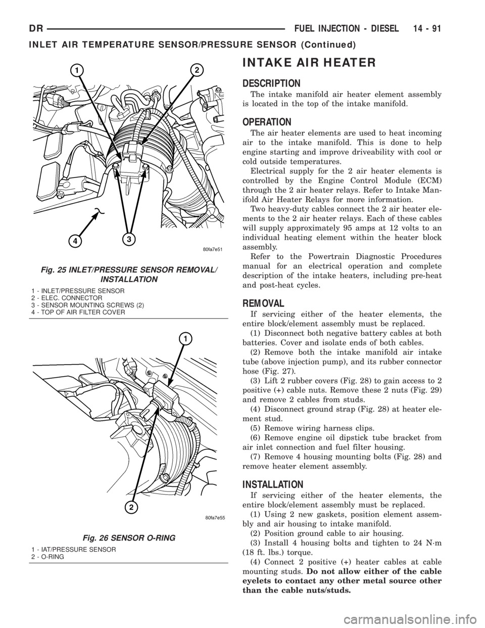
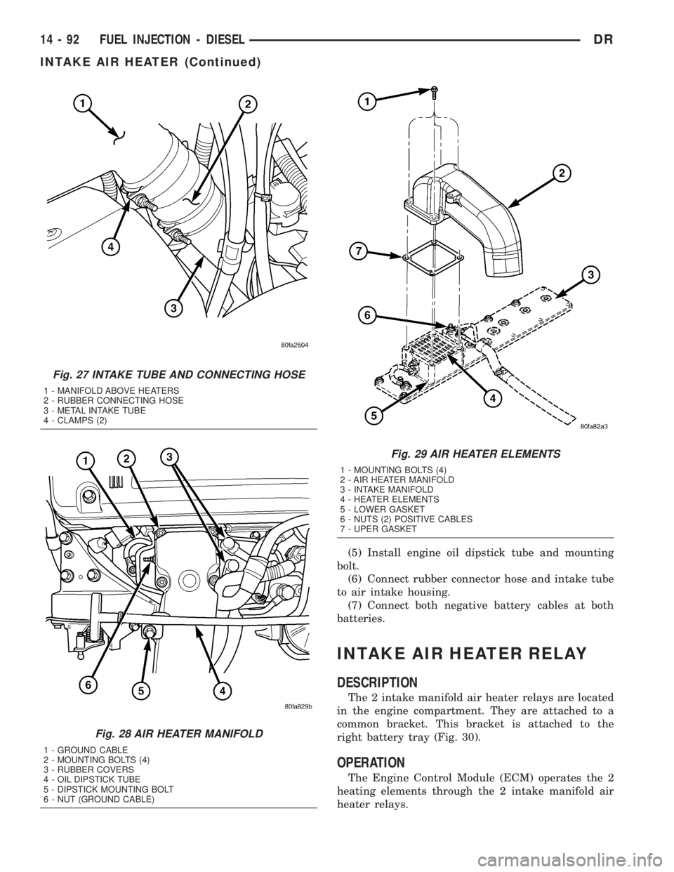
(2) Remove both the intake manifold air intake
tube (above injection pump), and its rubber connector
hose (Fig. 27).
(3) Lift 2 rubber covers (Fig. 28) to gain access to 2
positive (+) cable nuts. Remove these 2 nuts (Fig. 29)
and remove 2 cables from studs.
(4) Disconnect ground strap (Fig. 28) at heater ele-
ment stud.
(5) Remove wiring harness clips.
(6) Remove engine oil dipstick tube bracket from
air inlet connection and fuel filter housing.
(7) Remove 4 housing mounting bolts (Fig. 28) and
remove heater element assembly.
INSTALLATION
If servicing either of the heater elements, the
entire block/element assembly must be replaced.
(1) Using 2 new gaskets, position element assem-
bly and air housing to intake manifold.
(2) Position ground cable to air housing.
(3) Install 4 housing bolts and tighten to 24 N´m
(18 ft. lbs.) torque.
(4) Connect 2 positive (+) heater cables at cable
mounting studs.Do not allow either of the cable
eyelets to contact any other metal source other
than the cable nuts/studs.
Fig. 25 INLET/PRESSURE SENSOR REMOVAL/
INSTALLATION
1 - INLET/PRESSURE SENSOR
2 - ELEC. CONNECTOR
3 - SENSOR MOUNTING SCREWS (2)
4 - TOP OF AIR FILTER COVER
Fig. 26 SENSOR O-RING
1 - IAT/PRESSURE SENSOR
2 - O-RING
DRFUEL INJECTION - DIESEL 14 - 91
INLET AIR TEMPERATURE SENSOR/PRESSURE SENSOR (Continued)
Page 1789 of 2895
(5) Install engine oil dipstick tube and mounting
bolt.
(6) Connect rubber connector hose and intake tube
to air intake housing.
(7) Connect both negative battery cables at both
batteries.
INTAKE AIR HEATER RELAY
DESCRIPTION
The 2 intake manifold air heater relays are located
in the engine compartment. They are attached to a
common bracket. This bracket is attached to the
right battery tray (Fig. 30).
OPERATION
The Engine Control Module (ECM) operates the 2
heating elements through the 2 intake manifold air
heater relays.
Fig. 27 INTAKE TUBE AND CONNECTING HOSE
1 - MANIFOLD ABOVE HEATERS
2 - RUBBER CONNECTING HOSE
3 - METAL INTAKE TUBE
4 - CLAMPS (2)
Fig. 28 AIR HEATER MANIFOLD
1 - GROUND CABLE
2 - MOUNTING BOLTS (4)
3 - RUBBER COVERS
4 - OIL DIPSTICK TUBE
5 - DIPSTICK MOUNTING BOLT
6 - NUT (GROUND CABLE)
Fig. 29 AIR HEATER ELEMENTS
1 - MOUNTING BOLTS (4)
2 - AIR HEATER MANIFOLD
3 - INTAKE MANIFOLD
4 - HEATER ELEMENTS
5 - LOWER GASKET
6 - NUTS (2) POSITIVE CABLES
7 - UPER GASKET
14 - 92 FUEL INJECTION - DIESELDR
INTAKE AIR HEATER (Continued)
Page 1790 of 2895
Refer to Powertrain Diagnostic Procedures for an
electrical operation and complete description of the
intake heaters, including pre-heat and post-heat
cycles.
REMOVAL
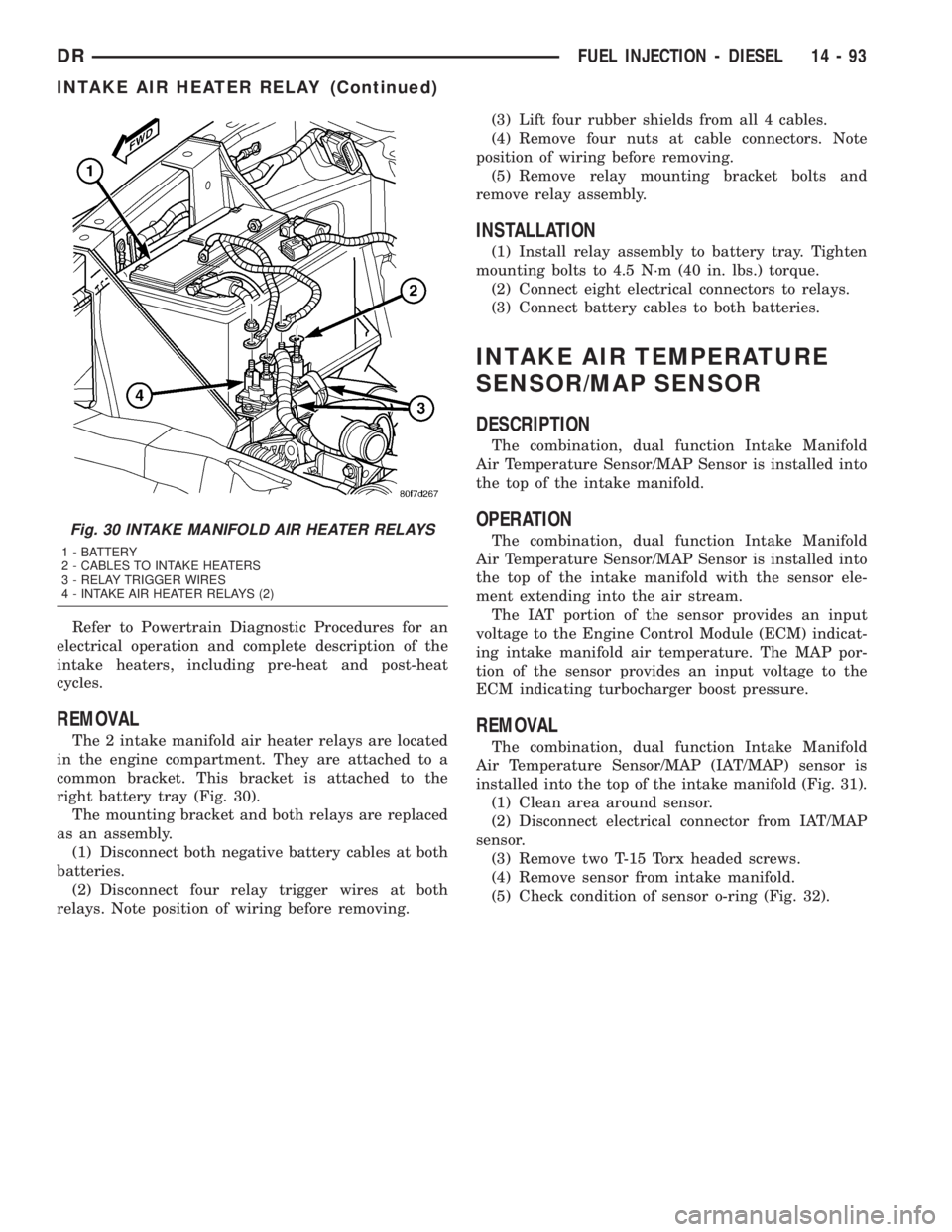
The 2 intake manifold air heater relays are located
in the engine compartment. They are attached to a
common bracket. This bracket is attached to the
right battery tray (Fig. 30).
The mounting bracket and both relays are replaced
as an assembly.
(1) Disconnect both negative battery cables at both
batteries.
(2) Disconnect four relay trigger wires at both
relays. Note position of wiring before removing.(3) Lift four rubber shields from all 4 cables.
(4) Remove four nuts at cable connectors. Note
position of wiring before removing.
(5) Remove relay mounting bracket bolts and
remove relay assembly.
INSTALLATION
(1) Install relay assembly to battery tray. Tighten
mounting bolts to 4.5 N´m (40 in. lbs.) torque.
(2) Connect eight electrical connectors to relays.
(3) Connect battery cables to both batteries.
INTAKE AIR TEMPERATURE
SENSOR/MAP SENSOR
DESCRIPTION
The combination, dual function Intake Manifold
Air Temperature Sensor/MAP Sensor is installed into
the top of the intake manifold.
OPERATION
The combination, dual function Intake Manifold
Air Temperature Sensor/MAP Sensor is installed into
the top of the intake manifold with the sensor ele-
ment extending into the air stream.
The IAT portion of the sensor provides an input
voltage to the Engine Control Module (ECM) indicat-
ing intake manifold air temperature. The MAP por-
tion of the sensor provides an input voltage to the
ECM indicating turbocharger boost pressure.
REMOVAL
The combination, dual function Intake Manifold
Air Temperature Sensor/MAP (IAT/MAP) sensor is
installed into the top of the intake manifold (Fig. 31).
(1) Clean area around sensor.
(2) Disconnect electrical connector from IAT/MAP
sensor.
(3) Remove two T-15 Torx headed screws.
(4) Remove sensor from intake manifold.
(5) Check condition of sensor o-ring (Fig. 32).
Fig. 30 INTAKE MANIFOLD AIR HEATER RELAYS
1 - BATTERY
2 - CABLES TO INTAKE HEATERS
3 - RELAY TRIGGER WIRES
4 - INTAKE AIR HEATER RELAYS (2)
DRFUEL INJECTION - DIESEL 14 - 93
INTAKE AIR HEATER RELAY (Continued)
Page 1992 of 2895
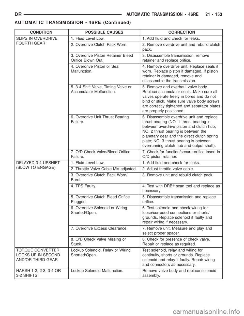
CONDITION POSSIBLE CAUSES CORRECTION
SLIPS IN OVERDRIVE
FOURTH GEAR1. Fluid Level Low. 1. Add fluid and check for leaks.
2. Overdrive Clutch Pack Worn. 2. Remove overdrive unit and rebuild clutch
pack.
3. Overdrive Piston Retainer Bleed
Orifice Blown Out.3. Disassemble transmission, remove
retainer and replace orifice.
4. Overdrive Piston or Seal
Malfunction.4. Remove overdrive unit. Replace seals if
worn. Replace piston if damaged. If piston
retainer is damaged, remove and
disassemble the transmission.
5. 3-4 Shift Valve, Timing Valve or
Accumulator Malfunction.5. Remove and overhaul valve body.
Replace accumulator seals. Make sure all
valves operate freely in bores and do not
bind or stick. Make sure valve body screws
are correctly tightened and separator plates
are properly positioned.
6. Overdrive Unit Thrust Bearing
Failure.6. Disassemble overdrive unit and replace
thrust bearing (NO. 1 thrust bearing is
between overdrive piston and clutch hub;
NO. 2 thrust bearing is between the
planetary gear and the direct clutch spring
plate; NO. 3 thrust bearing is between
overrunning clutch hub and output shaft).
7. O/D Check Valve/Bleed Orifice
Failure.7. Check for function/secure orifice insert in
O/D piston retainer.
DELAYED 3-4 UPSHIFT
(SLOW TO ENGAGE)1. Fluid Level Low. 1. Add fluid and check for leaks.
2. Throttle Valve Cable Mis-adjusted. 2. Adjust throttle valve cable.
3. Overdrive Clutch Pack Worn/
Burnt.3. Remove unit and rebuild clutch pack.
4. TPS Faulty. 4. Test with DRBTscan tool and replace as
necessary
5. Overdrive Clutch Bleed Orifice
Plugged.5. Disassemble transmission and replace
orifice.
6. Overdrive Solenoid or Wiring
Shorted/Open.6. Test solenoid and check wiring for
loose/corroded connections or shorts/
grounds. Replace solenoid if faulty and
repair wiring if necessary.
7. Overdrive Excess Clearance. 7. Remove unit. Measure end play and
select proper spacer.
8. O/D Check Valve Missing or
Stuck.8. Check for presence of check valve.
Repair or replace as required.
TORQUE CONVERTER
LOCKS UP IN SECOND
AND/OR THIRD GEARLockup Solenoid, Relay or Wiring
Shorted/Open.Test solenoid, relay and wiring for
continuity, shorts or grounds. Replace
solenoid and relay if faulty. Repair wiring
and connectors as necessary.
HARSH 1-2, 2-3, 3-4 OR
3-2 SHIFTSLockup Solenoid Malfunction. Remove valve body and replace solenoid
assembly.
DRAUTOMATIC TRANSMISSION - 46RE 21 - 153
AUTOMATIC TRANSMISSION - 46RE (Continued)
Page 2036 of 2895
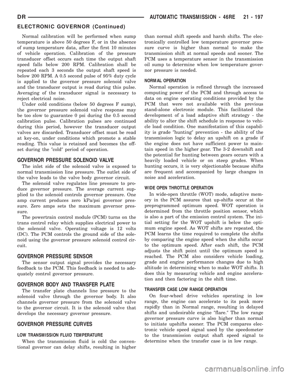
Normal calibration will be performed when sump
temperature is above 50 degrees F, or in the absence
of sump temperature data, after the first 10 minutes
of vehicle operation. Calibration of the pressure
transducer offset occurs each time the output shaft
speed falls below 200 RPM. Calibration shall be
repeated each 3 seconds the output shaft speed is
below 200 RPM. A 0.5 second pulse of 95% duty cycle
is applied to the governor pressure solenoid valve
and the transducer output is read during this pulse.
Averaging of the transducer signal is necessary to
reject electrical noise.
Under cold conditions (below 50 degrees F sump),
the governor pressure solenoid valve response may
be too slow to guarantee 0 psi during the 0.5 second
calibration pulse. Calibration pulses are continued
during this period, however the transducer output
valves are discarded. Transducer offset must be read
at key-on, under conditions which promote a stable
reading. This value is retained and becomes the off-
set during the9cold9period of operation.
GOVERNOR PRESSURE SOLENOID VALVE
The inlet side of the solenoid valve is exposed to
normal transmission line pressure. The outlet side of
the valve leads to the valve body governor circuit.
The solenoid valve regulates line pressure to pro-
duce governor pressure. The average current sup-
plied to the solenoid controls governor pressure. One
amp current produces zero kPa/psi governor pres-
sure. Zero amps sets the maximum governor pres-
sure.
The powertrain control module (PCM) turns on the
trans control relay which supplies electrical power to
the solenoid valve. Operating voltage is 12 volts
(DC). The PCM controls the ground side of the sole-
noid using the governor pressure solenoid control cir-
cuit.
GOVERNOR PRESSURE SENSOR
The sensor output signal provides the necessary
feedback to the PCM. This feedback is needed to ade-
quately control governor pressure.
GOVERNOR BODY AND TRANSFER PLATE
The transfer plate channels line pressure to the
solenoid valve through the governor body. It also
channels governor pressure from the solenoid valve
to the governor circuit. It is the solenoid valve that
develops the necessary governor pressure.
GOVERNOR PRESSURE CURVES
LOW TRANSMISSION FLUID TEMPERATURE
When the transmission fluid is cold the conven-
tional governor can delay shifts, resulting in higherthan normal shift speeds and harsh shifts. The elec-
tronically controlled low temperature governor pres-
sure curve is higher than normal to make the
transmission shift at normal speeds and sooner. The
PCM uses a temperature sensor in the transmission
oil sump to determine when low temperature gover-
nor pressure is needed.
NORMAL OPERATION
Normal operation is refined through the increased
computing power of the PCM and through access to
data on engine operating conditions provided by the
PCM that were not available with the previous
stand-alone electronic module. This facilitated the
development of a load adaptive shift strategy - the
ability to alter the shift schedule in response to vehi-
cle load condition. One manifestation of this capabil-
ity is grade9hunting9prevention - the ability of the
transmission logic to delay an upshift on a grade if
the engine does not have sufficient power to main-
tain speed in the higher gear. The 3-2 downshift and
the potential for hunting between gears occurs with a
heavily loaded vehicle or on steep grades. When
hunting occurs, it is very objectionable because shifts
are frequent and accompanied by large changes in
noise and acceleration.
WIDE OPEN THROTTLE OPERATION
In wide-open throttle (WOT) mode, adaptive mem-
ory in the PCM assures that up-shifts occur at the
preprogrammed optimum speed. WOT operation is
determined from the throttle position sensor, which
is also a part of the emission control system. The ini-
tial setting for the WOT upshift is below the opti-
mum engine speed. As WOT shifts are repeated, the
PCM learns the time required to complete the shifts
by comparing the engine speed when the shifts occur
to the optimum speed. After each shift, the PCM
adjusts the shift point until the optimum speed is
reached. The PCM also considers vehicle loading,
grade and engine performance changes due to high
altitude in determining when to make WOT shifts. It
does this by measuring vehicle and engine accelera-
tion and then factoring in the shift time.
TRANSFER CASE LOW RANGE OPERATION
On four-wheel drive vehicles operating in low
range, the engine can accelerate to its peak more
rapidly than in Normal range, resulting in delayed
shifts and undesirable engine9flare.9The low range
governor pressure curve is also higher than normal
to initiate upshifts sooner. The PCM compares elec-
tronic vehicle speed signal used by the speedometer
to the transmission output shaft speed signal to
determine when the transfer case is in low range.
DRAUTOMATIC TRANSMISSION - 46RE 21 - 197
ELECTRONIC GOVERNOR (Continued)
Page 2102 of 2895
tank. The valve prevents fluid drainback when the
vehicle is parked for lengthy periods. The valve check
ball is spring loaded and has an opening pressure of
approximately 2 psi.
The valve is serviced as an assembly; it is not repair-
able. Do not clean the valve if restricted, or contami-
nated by sludge, or debris. If the valve fails, or if a
transmission malfunction occurs that generates signifi-
cant amounts of sludge and/or clutch particles and
metal shavings, the valve must be replaced.
If the valve is restricted, installed backwards, or in
the wrong line, it will cause an overheating condition
and possible transmission failure.
CAUTION: The drainback valve is a one-way flow
device. It must be properly oriented in terms of flow
direction for the cooler to function properly. The
valve must be installed in the pressure line. Other-
wise flow will be blocked and would cause an over-
heating condition and eventual transmission failure.
TRANSMISSION RANGE
SENSOR
DESCRIPTION
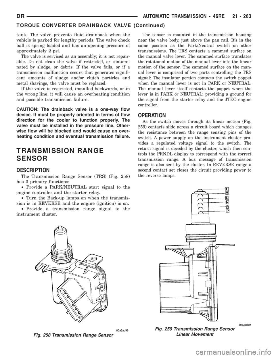
The Transmission Range Sensor (TRS) (Fig. 258)
has 3 primary functions:
²Provide a PARK/NEUTRAL start signal to the
engine controller and the starter relay.
²Turn the Back-up lamps on when the transmis-
sion is in REVERSE and the engine (ignition) is on.
²Provide a transmission range signal to the
instrument cluster.
The sensor is mounted in the transmission housing
near the valve body, just above the pan rail. It's in the
same position as the Park/Neutral switch on other
transmissions. The TRS contacts a cammed surface on
the manual valve lever. The cammed surface translates
the rotational motion of the manual lever into the linear
motion of the sensor. The cammed surface on the man-
ual lever is comprised of two parts controlling the TRS
signal: The insulator portion contacts the switch poppet
when the manual lever is not in PARK or NEUTRAL.
The manual lever itself contacts the poppet when the
lever is in PARK or NEUTRAL; providing a ground for
the signal from the starter relay and the JTEC engine
controller.
OPERATION
As the switch moves through its linear motion (Fig.
259) contacts slide across a circuit board which changes
the resistance between the range sensing pins of the
switch. A power supply on the instrument cluster pro-
vides a regulated voltage signal to the switch. The
return signal is decoded by the cluster, which then con-
trols the PRNDL display to correspond with the correct
transmission range. A bus message of transmission
range is also sent by the cluster. In REVERSE range a
second contact set closes the circuit providing power to
the reverse lamps.
Fig. 258 Transmission Range Sensor
Fig. 259 Transmission Range Sensor
Linear Movement
DRAUTOMATIC TRANSMISSION - 46RE 21 - 263
TORQUE CONVERTER DRAINBACK VALVE (Continued)
Page 2118 of 2895
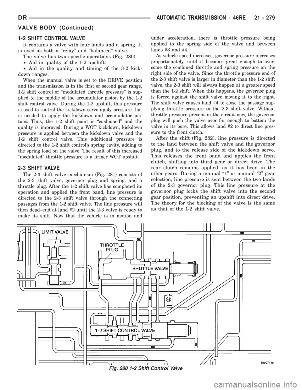
1-2 SHIFT CONTROL VALVE
It contains a valve with four lands and a spring. It
is used as both a ªrelayº and ªbalancedº valve.
The valve has two specific operations (Fig. 280):
²Aid in quality of the 1-2 upshift.
²Aid in the quality and timing of the 3-2 kick-
down ranges.
When the manual valve is set to the DRIVE position
and the transmission is in the first or second gear range,
1-2 shift control or ªmodulated throttle pressureº is sup-
plied to the middle of the accumulator piston by the 1-2
shift control valve. During the 1-2 upshift, this pressure
is used to control the kickdown servo apply pressure that
is needed to apply the kickdown and accumulator pis-
tons. Thus, the 1-2 shift point is ªcushionedº and the
quality is improved. During a WOT kickdown, kickdown
pressure is applied between the kickdown valve and the
1-2 shift control valve. This additional pressure is
directed to the 1-2 shift control's spring cavity, adding to
the spring load on the valve. The result of this increased
ªmodulatedº throttle pressure is a firmer WOT upshift.
2-3 SHIFT VALVE
The 2-3 shift valve mechanism (Fig. 281) consists of
the 2-3 shift valve, governor plug and spring, and a
throttle plug. After the 1-2 shift valve has completed its
operation and applied the front band, line pressure is
directed to the 2-3 shift valve through the connecting
passages from the 1-2 shift valve. The line pressure will
then dead±end at land #2 until the 2-3 valve is ready to
make its shift. Now that the vehicle is in motion andunder acceleration, there is throttle pressure being
applied to the spring side of the valve and between
lands #3 and #4.
As vehicle speed increases, governor pressure increases
proportionately, until it becomes great enough to over-
come the combined throttle and spring pressure on the
right side of the valve. Since the throttle pressure end of
the 2-3 shift valve is larger in diameter than the 1-2 shift
valve, the 2-3 shift will always happen at a greater speed
than the 1-2 shift. When this happens, the governor plug
is forced against the shift valve moving it to the right.
The shift valve causes land #4 to close the passage sup-
plying throttle pressure to the 2-3 shift valve. Without
throttle pressure present in the circuit now, the governor
plug will push the valve over far enough to bottom the
valve in its bore. This allows land #2 to direct line pres-
sure to the front clutch.
After the shift (Fig. 282), line pressure is directed
to the land between the shift valve and the governor
plug, and to the release side of the kickdown servo.
This releases the front band and applies the front
clutch, shifting into third gear or direct drive. The
rear clutch remains applied, as it has been in the
other gears. During a manual ª1º or manual ª2º gear
selection, line pressure is sent between the two lands
of the 2-3 governor plug. This line pressure at the
governor plug locks the shift valve into the second
gear position, preventing an upshift into direct drive.
The theory for the blocking of the valve is the same
as that of the 1-2 shift valve.
Fig. 280 1-2 Shift Control Valve
DRAUTOMATIC TRANSMISSION - 46RE 21 - 279
VALVE BODY (Continued)