2003 DODGE RAM relay
[x] Cancel search: relayPage 2421 of 2895
TRANSMISSION SOLENOID/
TRS ASSEMBLY
DESCRIPTION
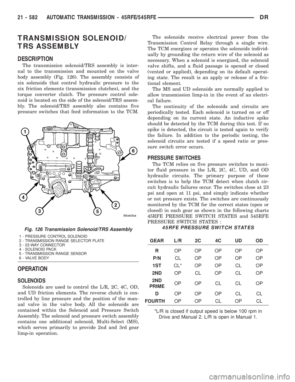
The transmission solenoid/TRS assembly is inter-
nal to the transmission and mounted on the valve
body assembly (Fig. 126). The assembly consists of
six solenoids that control hydraulic pressure to the
six friction elements (transmission clutches), and the
torque converter clutch. The pressure control sole-
noid is located on the side of the solenoid/TRS assem-
bly. The solenoid/TRS assembly also contains five
pressure switches that feed information to the TCM.
OPERATION
SOLENOIDS
Solenoids are used to control the L/R, 2C, 4C, OD,
and UD friction elements. The reverse clutch is con-
trolled by line pressure and the position of the man-
ual valve in the valve body. All the solenoids are
contained within the Solenoid and Pressure Switch
Assembly. The solenoid and pressure switch assembly
contains one additional solenoid, Multi-Select (MS),
which serves primarily to provide 2nd and 3rd gear
limp-in operation.The solenoids receive electrical power from the
Transmission Control Relay through a single wire.
The TCM energizes or operates the solenoids individ-
ually by grounding the return wire of the solenoid as
necessary. When a solenoid is energized, the solenoid
valve shifts, and a fluid passage is opened or closed
(vented or applied), depending on its default operat-
ing state. The result is an apply or release of a fric-
tional element.
The MS and UD solenoids are normally applied to
allow transmission limp-in in the event of an electri-
cal failure.
The continuity of the solenoids and circuits are
periodically tested. Each solenoid is turned on or off
depending on its current state. An inductive spike
should be detected by the TCM during this test. If no
spike is detected, the circuit is tested again to verify
the failure. In addition to the periodic testing, the
solenoid circuits are tested if a speed ratio or pres-
sure switch error occurs.
PRESSURE SWITCHES
The TCM relies on five pressure switches to moni-
tor fluid pressure in the L/R, 2C, 4C, UD, and OD
hydraulic circuits. The primary purpose of these
switches is to help the TCM detect when clutch cir-
cuit hydraulic failures occur. The switches close at 23
psi and open at 11 psi, and simply indicate whether
or not pressure exists. The switches are continuously
monitored by the TCM for the correct states (open or
closed) in each gear as shown in the following charts
45RFE PRESSURE SWITCH STATES and 545RFE
PRESSURE SWITCH STATES :
45RFE PRESSURE SWITCH STATES
GEAR L/R 2C 4C UD OD
ROP OP OP OP OP
P/NCL OP OP OP OP
1STCL* OP OP CL OP
2NDOP CL OP CL OP
2ND
PRIMEOP OP CL CL OP
DOP OP OP CL CL
FOURTHOP OP CL OP CL
*L/R is closed if output speed is below 100 rpm in
Drive and Manual 2. L/R is open in Manual 1.
Fig. 126 Transmission Solenoid/TRS Assembly
1 - PRESSURE CONTROL SOLENOID
2 - TRANSMISSION RANGE SELECTOR PLATE
3 - 23-WAY CONNECTOR
4 - SOLENOID PACK
5 - TRANSMISSION RANGE SENSOR
6 - VALVE BODY
21 - 582 AUTOMATIC TRANSMISSION - 45RFE/545RFEDR
Page 2424 of 2895
OPERATION
NOTE: Refer to the Hydraulic Schematics for a
visual aid in determining valve location, operation
and design.
SOLENOID SWITCH VALVE
The Solenoid Switch Valve (SSV) controls the direc-
tion of the transmission fluid when the L/R-TCC sole-
noid is energized.
When shifting into 1st gear, a special hydraulic
sequence is performed to ensure SSV movement into
the downshifted position. The L/R pressure switch is
monitored to confirm SSV movement. If the move-
ment is not confirmed (the L/R pressure switch does
not close), 2nd gear is substituted for 1st. A DTC will
be set after three unsuccessful attempts are made to
get into 1st gear in one given key start.
MANUAL VALVE
The manual valve is a relay valve. The purpose of
the manual valve is to direct fluid to the correct cir-
cuit needed for a specific gear or driving range. The
manual valve, as the name implies, is manually oper-
ated by the driver with a lever located on the top of
the valve body. The valve is connected mechanically
by a cable to the gearshift mechanism. The valve is
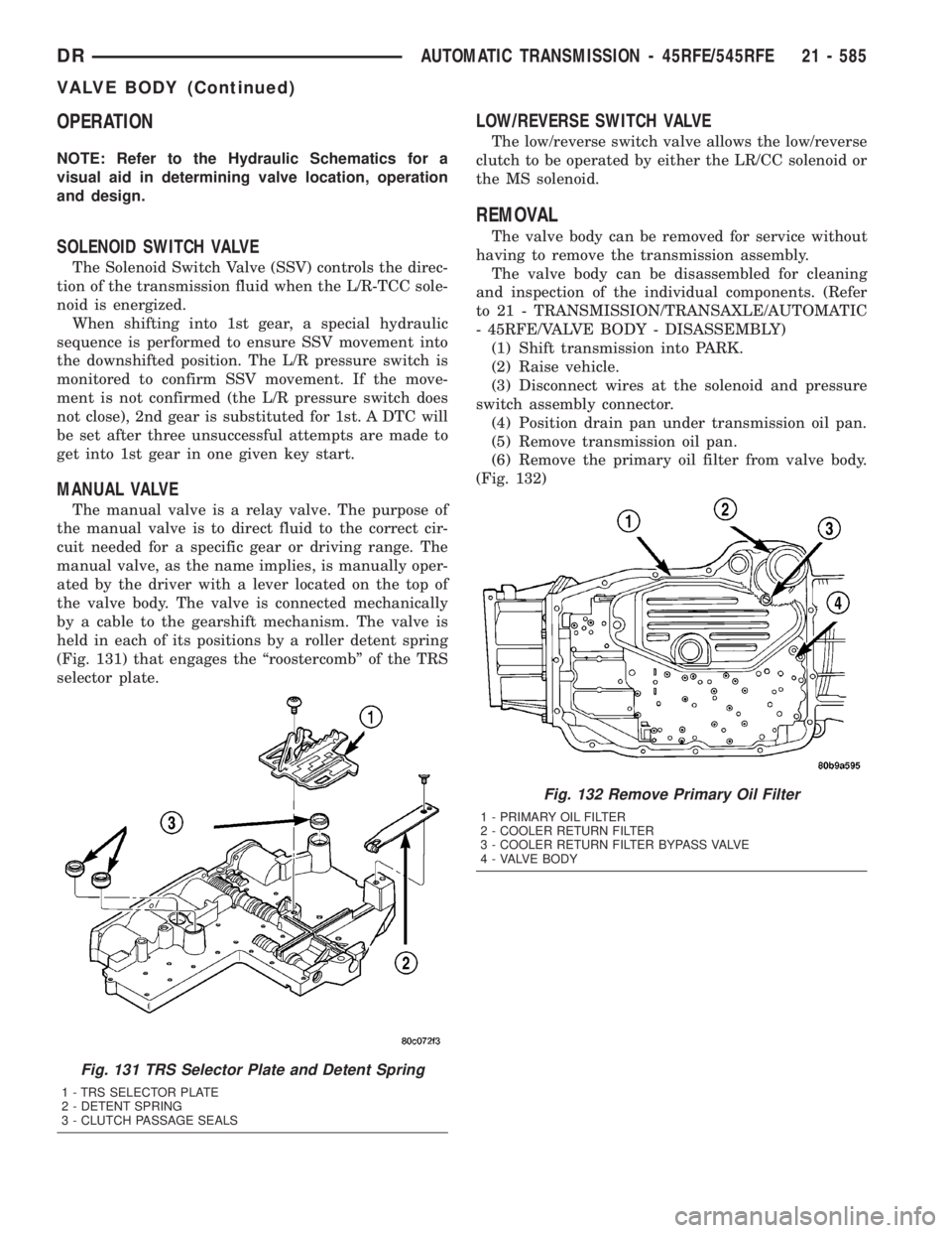
held in each of its positions by a roller detent spring
(Fig. 131) that engages the ªroostercombº of the TRS
selector plate.
LOW/REVERSE SWITCH VALVE
The low/reverse switch valve allows the low/reverse
clutch to be operated by either the LR/CC solenoid or
the MS solenoid.
REMOVAL
The valve body can be removed for service without
having to remove the transmission assembly.
The valve body can be disassembled for cleaning
and inspection of the individual components. (Refer
to 21 - TRANSMISSION/TRANSAXLE/AUTOMATIC
- 45RFE/VALVE BODY - DISASSEMBLY)
(1) Shift transmission into PARK.
(2) Raise vehicle.
(3) Disconnect wires at the solenoid and pressure
switch assembly connector.
(4) Position drain pan under transmission oil pan.
(5) Remove transmission oil pan.
(6) Remove the primary oil filter from valve body.
(Fig. 132)
Fig. 131 TRS Selector Plate and Detent Spring
1 - TRS SELECTOR PLATE
2 - DETENT SPRING
3 - CLUTCH PASSAGE SEALS
Fig. 132 Remove Primary Oil Filter
1 - PRIMARY OIL FILTER
2 - COOLER RETURN FILTER
3 - COOLER RETURN FILTER BYPASS VALVE
4 - VALVE BODY
DRAUTOMATIC TRANSMISSION - 45RFE/545RFE 21 - 585
VALVE BODY (Continued)
Page 2779 of 2895
Pressure Diagnosis
Condition Possible Causes Correction
4. Faulty a/c compressor
clutch relay.4. See A/C Compressor Clutch Relay/Diagnosis
and Testing - Compressor Clutch Relay in this
group. Test the compressor clutch relay and relay
circuits. Repair the circuits or replace the relay, if
required.
5. Improperly installed or
faulty Fin Sensor.5. See Fin Sensor/Diagnosis and Testing in this
group. Reinstall or replace the Fin Sensor as
required.
6. Faulty a/c high pressure
transducer.6. See A/C High Pressure Transducer/Diagnosis
and Testing in this group. Test the a/c high
pressure transducer and replace, if required.
7. Faulty Powertrain Control
Module (PCM).7. (Refer to Appropriate Diagnostic Information).
Test the PCM and replace, if required.
Normal pressures, but A/C
Performance Test air
temperatures at center panel
outlet are too high.1. Excessive refrigerant oil in
system.1. See Refrigerant Oil/Standard Procedure -
Refrigerant Oil Level in this group. Recover the
refrigerant from the refrigerant system and
inspect the refrigerant oil content. Restore the
refrigerant oil to the proper level, if required.
2. Blend door inoperative or
sealing improperly.2. See Blend Door in this group. Inspect the
blend door for proper operation and sealing and
correct, if required.
3. Blend door actuator faulty
or inoperative.3. Perform blend door actuator diagnosis, replace
if faulty.
The low side pressure is
normal or slightly low, and
the high side pressure is too
low.1. Low refrigerant system
charge.1. See Plumbing/Diagnosis and Testing -
Refrigerant System Leaks in this group. Test the
refrigerant system for leaks. Repair, evacuate and
charge the refrigerant system, if required.
2. Refrigerant flow through
the accumulator is restricted.2. See Accumulator in this group. Replace the
restricted accumulator, if required.
3. Refrigerant flow through
the evaporator coil is
restricted.3. See A/C Evaporator in this group. Replace the
restricted evaporator coil, if required.
4. Faulty compressor. 4. See A/C Compressor in this group. Replace
the compressor, if required.
The low side pressure is
normal or slightly high, and
the high side pressure is too
high.1. Condenser air flow
restricted.1. Check the condenser for damaged fins, foreign
objects obstructing air flow through the condenser
fins, and missing or improperly installed air seals.
Refer to Cooling for more information on air
seals. Clean, repair, or replace components as
required.
2. Inoperative cooling fan. 2. Refer to Cooling for more information. Test the
cooling fan and replace, if required.
3. Refrigerant system
overcharged.3. See Plumbing/Standard Procedure -
Refrigerant System Charge in this group. Recover
the refrigerant from the refrigerant system.
Charge the refrigerant system to the proper level,
if required.
24 - 4 HEATING & AIR CONDITIONINGDR
HEATING & AIR CONDITIONING (Continued)
Page 2782 of 2895
STANDARD PROCEDURE - DIODE
REPLACEMENT
(1) Disconnect the battery negative cable and iso-
late it. If vehicle has a dual batterys remove both
negative cables.
(2) Locate the diode in the harness, and remove
the protective covering.
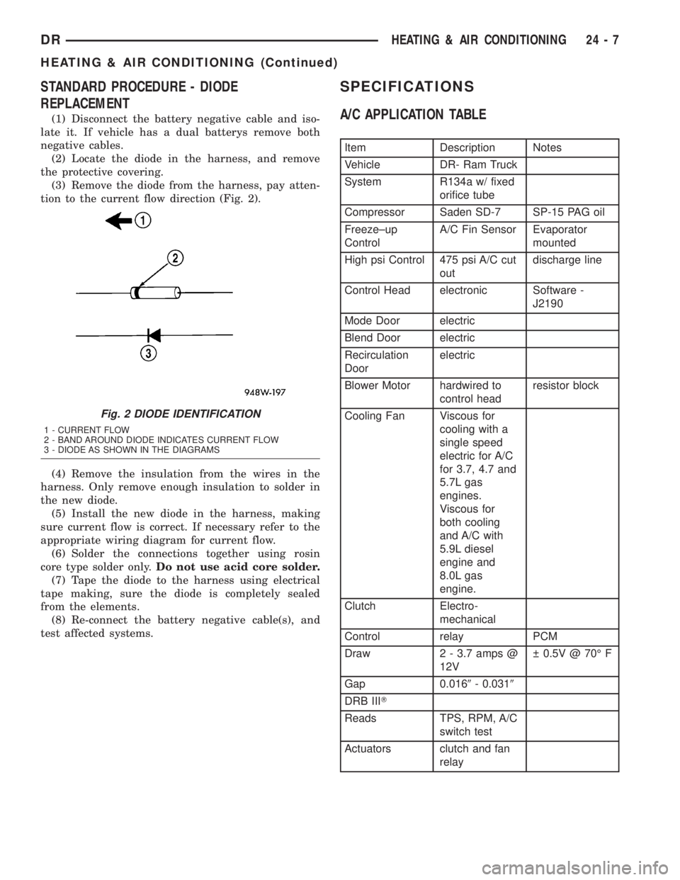
(3) Remove the diode from the harness, pay atten-
tion to the current flow direction (Fig. 2).
(4) Remove the insulation from the wires in the
harness. Only remove enough insulation to solder in
the new diode.
(5) Install the new diode in the harness, making
sure current flow is correct. If necessary refer to the
appropriate wiring diagram for current flow.
(6) Solder the connections together using rosin
core type solder only.Do not use acid core solder.
(7) Tape the diode to the harness using electrical
tape making, sure the diode is completely sealed
from the elements.
(8) Re-connect the battery negative cable(s), and
test affected systems.
SPECIFICATIONS
A/C APPLICATION TABLE
Item Description Notes
Vehicle DR- Ram Truck
System R134a w/ fixed
orifice tube
Compressor Saden SD-7 SP-15 PAG oil
Freeze±up
ControlA/C Fin Sensor Evaporator
mounted
High psi Control 475 psi A/C cut
outdischarge line
Control Head electronic Software -
J2190
Mode Door electric
Blend Door electric
Recirculation
Doorelectric
Blower Motor hardwired to
control headresistor block
Cooling Fan Viscous for
cooling with a
single speed
electric for A/C
for 3.7, 4.7 and
5.7L gas
engines.
Viscous for
both cooling
and A/C with
5.9L diesel
engine and
8.0L gas
engine.
Clutch Electro-
mechanical
Control relay PCM
Draw 2 - 3.7 amps @
12V 0.5V @ 70É F
Gap 0.0169- 0.0319
DRB IIIT
Reads TPS, RPM, A/C
switch test
Actuators clutch and fan
relay
Fig. 2 DIODE IDENTIFICATION
1 - CURRENT FLOW
2 - BAND AROUND DIODE INDICATES CURRENT FLOW
3 - DIODE AS SHOWN IN THE DIAGRAMS
DRHEATING & AIR CONDITIONING 24 - 7
HEATING & AIR CONDITIONING (Continued)
Page 2784 of 2895
CONTROLS
TABLE OF CONTENTS
page page
A/C COMPRESSOR CLUTCH
DESCRIPTION..........................9
OPERATION............................9
DIAGNOSIS AND TESTING - A/C
COMPRESSOR CLUTCH COIL...........10
STANDARD PROCEDURE - A/C
COMPRESSOR CLUTCH BREAK-IN.......10
REMOVAL.............................10
INSPECTION..........................12
INSTALLATION.........................12
A/C COMPRESSOR CLUTCH RELAY
DESCRIPTION.........................13
OPERATION...........................13
DIAGNOSIS AND TESTING - COMPRESSOR
CLUTCH RELAY......................13
REMOVAL.............................14
INSTALLATION.........................14
A/C HEATER CONTROL
DESCRIPTION.........................14
REMOVAL.............................14
INSTALLATION.........................15
A/C PRESSURE TRANSDUCER
DESCRIPTION - A/C PRESSURE
TRANSDUCER.......................15
OPERATION...........................15
DIAGNOSIS AND TESTING - A/C PRESSURE
TRANSDUCER.......................15
REMOVAL.............................16
INSTALLATION.........................16
BLEND DOOR ACTUATOR
DESCRIPTION.........................16
OPERATION...........................16REMOVAL.............................17
INSTALLATION.........................17
BLOWER MOTOR RESISTOR BLOCK
DESCRIPTION.........................17
OPERATION...........................17
DIAGNOSIS AND TESTING - BLOWER
MOTOR RESISTOR....................18
REMOVAL.............................18
INSTALLATION.........................18
BLOWER MOTOR SWITCH
DESCRIPTION.........................18
OPERATION...........................18
DIAGNOSIS AND TESTING - BLOWER
MOTOR SWITCH......................18
REMOVAL.............................19
INSTALLATION.........................19
DEFROST DOOR ACTUATOR
REMOVAL - FLOOR - DEFROST DOOR
ACTUATOR..........................19
INSTALLATION - FLOOR - DEFROST DOOR
ACTUATOR..........................20
MODE DOOR ACTUATOR
DESCRIPTION.........................20
OPERATION...........................21
REMOVAL.............................21
INSTALLATION.........................22
RECIRCULATION DOOR ACTUATOR
DESCRIPTION.........................22
OPERATION...........................22
REMOVAL.............................22
INSTALLATION.........................23
A/C COMPRESSOR CLUTCH
DESCRIPTION
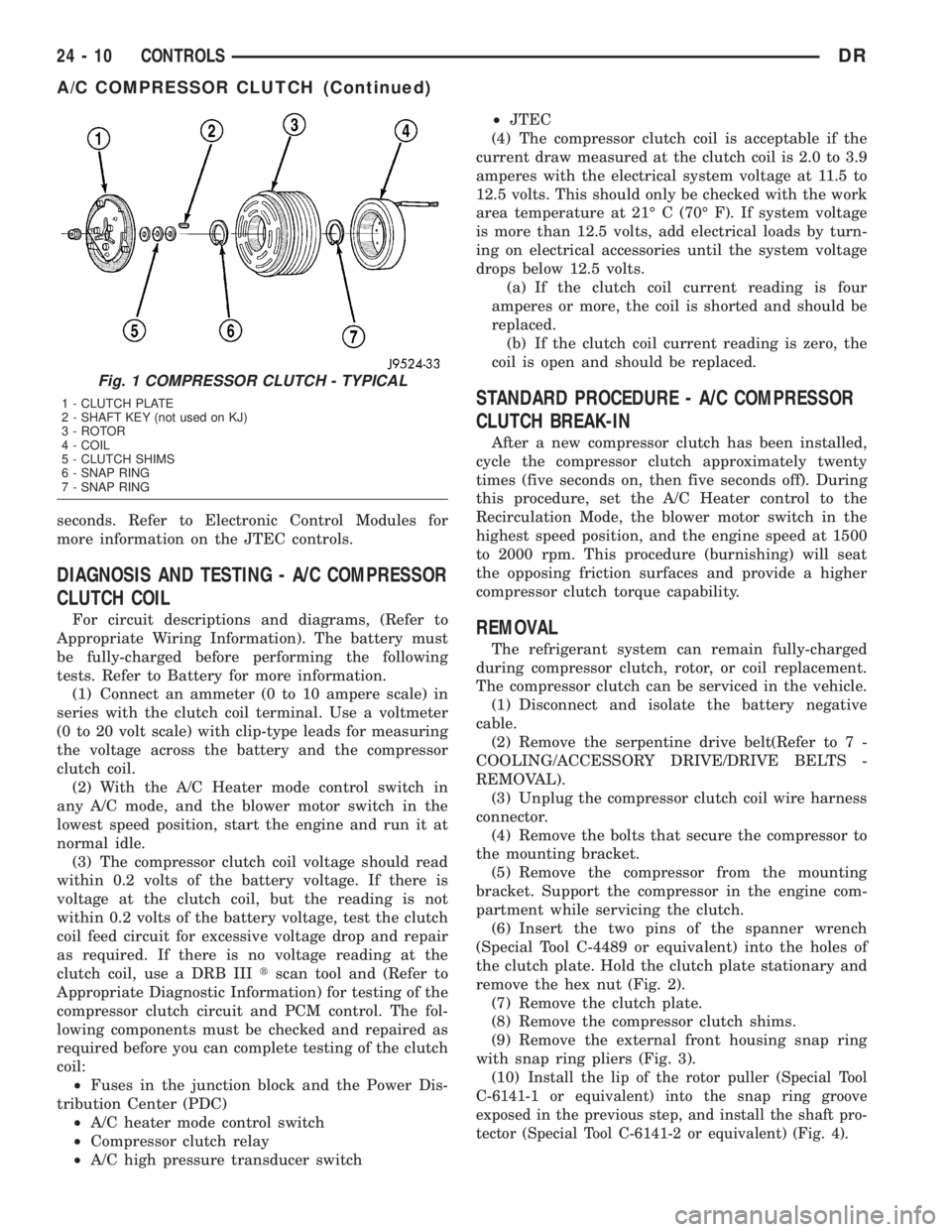
The compressor clutch assembly consists of a sta-
tionary electromagnetic coil, a rotor bearing and
rotor assembly, and a clutch plate (Fig. 1). The elec-
tromagnetic coil unit and the rotor bearing and rotor
assembly are each retained on the nose of the com-
pressor front housing with snap rings. The clutch
plate is keyed to the compressor shaft and secured
with a nut. These components provide the means to
engage and disengage the compressor from the
engine serpentine accessory drive belt.
OPERATION
When the clutch coil is energized, it magnetically
draws the clutch into contact with the rotor and
drives the compressor shaft. When the coil is not
energized, the rotor freewheels on the clutch rotor
bearing, which is part of the rotor. The compressor
clutch and coil are the only serviced parts on the
compressor.
The compressor clutch engagement is controlled by
several components: the A/C Heater mode control
switch, the A/C high pressure transducer, the com-
pressor clutch relay, and the (JTEC). The JTEC may
delay compressor clutch engagement for up to thirty
DRCONTROLS 24 - 9
Page 2785 of 2895
seconds. Refer to Electronic Control Modules for
more information on the JTEC controls.
DIAGNOSIS AND TESTING - A/C COMPRESSOR
CLUTCH COIL
For circuit descriptions and diagrams, (Refer to
Appropriate Wiring Information). The battery must
be fully-charged before performing the following
tests. Refer to Battery for more information.
(1) Connect an ammeter (0 to 10 ampere scale) in
series with the clutch coil terminal. Use a voltmeter
(0 to 20 volt scale) with clip-type leads for measuring
the voltage across the battery and the compressor
clutch coil.
(2) With the A/C Heater mode control switch in
any A/C mode, and the blower motor switch in the
lowest speed position, start the engine and run it at
normal idle.
(3) The compressor clutch coil voltage should read
within 0.2 volts of the battery voltage. If there is
voltage at the clutch coil, but the reading is not
within 0.2 volts of the battery voltage, test the clutch
coil feed circuit for excessive voltage drop and repair
as required. If there is no voltage reading at the
clutch coil, use a DRB IIItscan tool and (Refer to
Appropriate Diagnostic Information) for testing of the
compressor clutch circuit and PCM control. The fol-
lowing components must be checked and repaired as
required before you can complete testing of the clutch
coil:
²Fuses in the junction block and the Power Dis-
tribution Center (PDC)
²A/C heater mode control switch
²Compressor clutch relay
²A/C high pressure transducer switch²JTEC
(4) The compressor clutch coil is acceptable if the
current draw measured at the clutch coil is 2.0 to 3.9
amperes with the electrical system voltage at 11.5 to
12.5 volts. This should only be checked with the work
area temperature at 21É C (70É F). If system voltage
is more than 12.5 volts, add electrical loads by turn-
ing on electrical accessories until the system voltage
drops below 12.5 volts.
(a) If the clutch coil current reading is four
amperes or more, the coil is shorted and should be
replaced.
(b) If the clutch coil current reading is zero, the
coil is open and should be replaced.
STANDARD PROCEDURE - A/C COMPRESSOR
CLUTCH BREAK-IN
After a new compressor clutch has been installed,
cycle the compressor clutch approximately twenty
times (five seconds on, then five seconds off). During
this procedure, set the A/C Heater control to the
Recirculation Mode, the blower motor switch in the
highest speed position, and the engine speed at 1500
to 2000 rpm. This procedure (burnishing) will seat
the opposing friction surfaces and provide a higher
compressor clutch torque capability.
REMOVAL
The refrigerant system can remain fully-charged
during compressor clutch, rotor, or coil replacement.
The compressor clutch can be serviced in the vehicle.
(1) Disconnect and isolate the battery negative
cable.
(2) Remove the serpentine drive belt(Refer to 7 -
COOLING/ACCESSORY DRIVE/DRIVE BELTS -
REMOVAL).
(3) Unplug the compressor clutch coil wire harness
connector.
(4) Remove the bolts that secure the compressor to
the mounting bracket.
(5) Remove the compressor from the mounting
bracket. Support the compressor in the engine com-
partment while servicing the clutch.
(6) Insert the two pins of the spanner wrench
(Special Tool C-4489 or equivalent) into the holes of
the clutch plate. Hold the clutch plate stationary and
remove the hex nut (Fig. 2).
(7) Remove the clutch plate.
(8) Remove the compressor clutch shims.
(9) Remove the external front housing snap ring
with snap ring pliers (Fig. 3).
(10)
Install the lip of the rotor puller (Special Tool
C-6141-1 or equivalent) into the snap ring groove
exposed in the previous step, and install the shaft pro-
tector (Special Tool C-6141-2 or equivalent) (Fig. 4).
Fig. 1 COMPRESSOR CLUTCH - TYPICAL
1 - CLUTCH PLATE
2 - SHAFT KEY (not used on KJ)
3 - ROTOR
4 - COIL
5 - CLUTCH SHIMS
6 - SNAP RING
7 - SNAP RING
24 - 10 CONTROLSDR
A/C COMPRESSOR CLUTCH (Continued)
Page 2788 of 2895
NOTE: The air gap is determined by the spacer
shims. When installing an original, or a new clutch
assembly, try the original shims first. When install-
ing a new clutch onto a compressor that previously
did not have a clutch, use a 1.0, 0.50, and 0.13 mil-
limeter (0.040, 0.020, and 0.005 inch) shims from the
new clutch hardware package that is provided with
the new clutch.
(9) To complete the procedure, (Refer to 24 -
HEATING & AIR CONDITIONING/PLUMBING/A/C
COMPRESSOR - INSTALLATION).
A/C COMPRESSOR CLUTCH
RELAY
DESCRIPTION
The compressor clutch relay is a International
Standards Organization (ISO) micro-relay. The termi-
nal designations and functions are the same as a con-
ventional ISO relay. However, the micro-relay
terminal orientation (footprint) is different, the cur-
rent capacity is lower, and the relay case dimensions
are smaller than those of the conventional ISO relay.
The compressor clutch relay is located in the Power
Distribution Center (PDC) in the engine compart-
ment. Refer to the PDC label for relay identification
and location.
OPERATION
The compressor clutch relay is a electromechanical
device that switches battery current to the compres-
sor clutch coil when the Powertrain Control Module
(PCM) grounds the coil side of the relay. The PCM
responds to inputs from the A/C Heater mode control
switch, the A/C low pressure switch, and the A/C
high pressure switch. (Refer to 24 - HEATING & AIR
CONDITIONING/CONTROLS/A/C COMPRESSOR
CLUTCH RELAY - DIAGNOSIS AND TESTING)
The compressor clutch relay cannot be repaired
and, if faulty or damaged, it must be replaced.
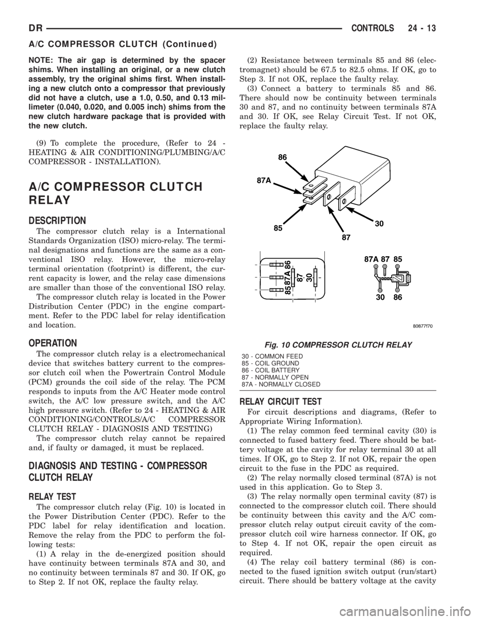
DIAGNOSIS AND TESTING - COMPRESSOR
CLUTCH RELAY
RELAY TEST
The compressor clutch relay (Fig. 10) is located in
the Power Distribution Center (PDC). Refer to the
PDC label for relay identification and location.
Remove the relay from the PDC to perform the fol-
lowing tests:
(1) A relay in the de-energized position should
have continuity between terminals 87A and 30, and
no continuity between terminals 87 and 30. If OK, go
to Step 2. If not OK, replace the faulty relay.(2) Resistance between terminals 85 and 86 (elec-
tromagnet) should be 67.5 to 82.5 ohms. If OK, go to
Step 3. If not OK, replace the faulty relay.
(3) Connect a battery to terminals 85 and 86.
There should now be continuity between terminals
30 and 87, and no continuity between terminals 87A
and 30. If OK, see Relay Circuit Test. If not OK,
replace the faulty relay.
RELAY CIRCUIT TEST
For circuit descriptions and diagrams, (Refer to
Appropriate Wiring Information).
(1) The relay common feed terminal cavity (30) is
connected to fused battery feed. There should be bat-
tery voltage at the cavity for relay terminal 30 at all
times. If OK, go to Step 2. If not OK, repair the open
circuit to the fuse in the PDC as required.
(2) The relay normally closed terminal (87A) is not
used in this application. Go to Step 3.
(3) The relay normally open terminal cavity (87) is
connected to the compressor clutch coil. There should
be continuity between this cavity and the A/C com-
pressor clutch relay output circuit cavity of the com-
pressor clutch coil wire harness connector. If OK, go
to Step 4. If not OK, repair the open circuit as
required.
(4) The relay coil battery terminal (86) is con-
nected to the fused ignition switch output (run/start)
circuit. There should be battery voltage at the cavity
Fig. 10 COMPRESSOR CLUTCH RELAY
30 - COMMON FEED
85 - COIL GROUND
86 - COIL BATTERY
87 - NORMALLY OPEN
87A - NORMALLY CLOSED
DRCONTROLS 24 - 13
A/C COMPRESSOR CLUTCH (Continued)
Page 2789 of 2895
for relay terminal 86 with the ignition switch in the
On position. If OK, go to Step 5. If not OK, repair the
open circuit to the fuse in the junction block as
required.
(5) The coil ground terminal cavity (85) is switched
to ground through the Powertrain Control Module
(PCM). There should be continuity between this cav-
ity and the A/C compressor clutch relay control cir-
cuit cavity of the PCM wire harness connector C
(gray) at all times. If not OK, repair the open circuit
as required.
REMOVAL
(1) Disconnect and isolate the battery negative
cable.
(2) Remove the cover from the Power Distribution
Center (PDC).
(3) Refer to the label on the PDC for compressor
clutch relay identification and location.
(4) Unplug the compressor clutch relay from the
PDC.
INSTALLATION
(1) Install the compressor clutch relay by aligning
the relay terminals with the cavities in the PDC and
pushing the relay firmly into place.
(2) Install the PDC cover.
(3) Connect the battery negative cable.
(4) Test the relay operation.
A/C HEATER CONTROL
DESCRIPTION
The A/C heater system uses a seriers of electrical
controls. These controls provide the vehicle operator
with a number of setting options to help control the
climate and comfort within the vehicle. Refer to the
owner's manual in the vehicle glove box for more
information on the features, use, and suggested oper-
ation of these controls.
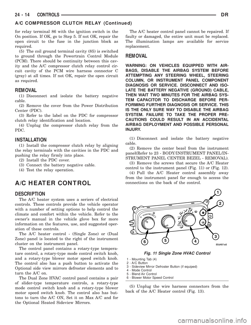
The A/C heater control - (Single Zone) or (Dual
Zone) panel is located to the right of the instrument
cluster on the instrument panel.
The control panel contains a rotary-type tempera-
ture control, a rotary-type mode control switch knob,
and a rotary-type blower motor speed switch knob.
The control also has a push button to activate the
Optional side view mirrors defroster elements and to
turn the A/C on.
The Dual Zone HVAC control panel contains a pair
of slider-type temperature controls, a rotary-type
mode control switch knob and a rotary-type blower
motor speed switch knob. The control also has but-
tons to turn the A/C ON, Set it on Max A/C and for
the Optional Heated Sideview Mirrors.The A/C heater control panel cannot be repaired. If
faulty or damaged, the entire unit must be replaced.
The illumination lamps are available for service
replacement.
REMOVAL
WARNING: ON VEHICLES EQUIPPED WITH AIR-
BAGS, DISABLE THE AIRBAG SYSTEM BEFORE
ATTEMPTING ANY STEERING WHEEL, STEERING
COLUMN, OR INSTRUMENT PANEL COMPONENT
DIAGNOSIS OR SERVICE. DISCONNECT AND ISO-
LATE THE BATTERY NEGATIVE (GROUND) CABLE,
THEN WAIT TWO MINUTES FOR THE AIRBAG SYS-
TEM CAPACITOR TO DISCHARGE BEFORE PER-
FORMING FURTHER DIAGNOSIS OR SERVICE. THIS
IS THE ONLY SURE WAY TO DISABLE THE AIRBAG
SYSTEM. FAILURE TO TAKE THE PROPER PRE-
CAUTIONS COULD RESULT IN AN ACCIDENTAL
AIRBAG DEPLOYMENT AND POSSIBLE PERSONAL
INJURY.
(1) Disconnect and isolate the battery negative
cable.
(2) Remove the center bezel from the instrument
panel(Refer to 23 - BODY/INSTRUMENT PANEL/IN-
STRUMENT PANEL CENTER BEZEL - REMOVAL).
(3) Remove the screws that secure the A/C Heater
control to the instrument panel (Fig. 11) or (Fig. 12).
(4) Pull the A/C Heater control assembly away
from the instrument panel far enough to access the
connections on the back of the control.
(5) Unplug the wire harness connectors from the
back of the A/C Heater control (Fig. 13).
Fig. 11 Single Zone HVAC Control
1 - Mounting Tab (4)
2 - A/C Button
3 - Sideview Mirror Defroster Button (if equiped)
4 - Mode Control
5 - Blend Air Control
6 - Blower Motor Speed Control
24 - 14 CONTROLSDR
A/C COMPRESSOR CLUTCH RELAY (Continued)