2003 DODGE RAM relay
[x] Cancel search: relayPage 2124 of 2895
MANUAL VALVE
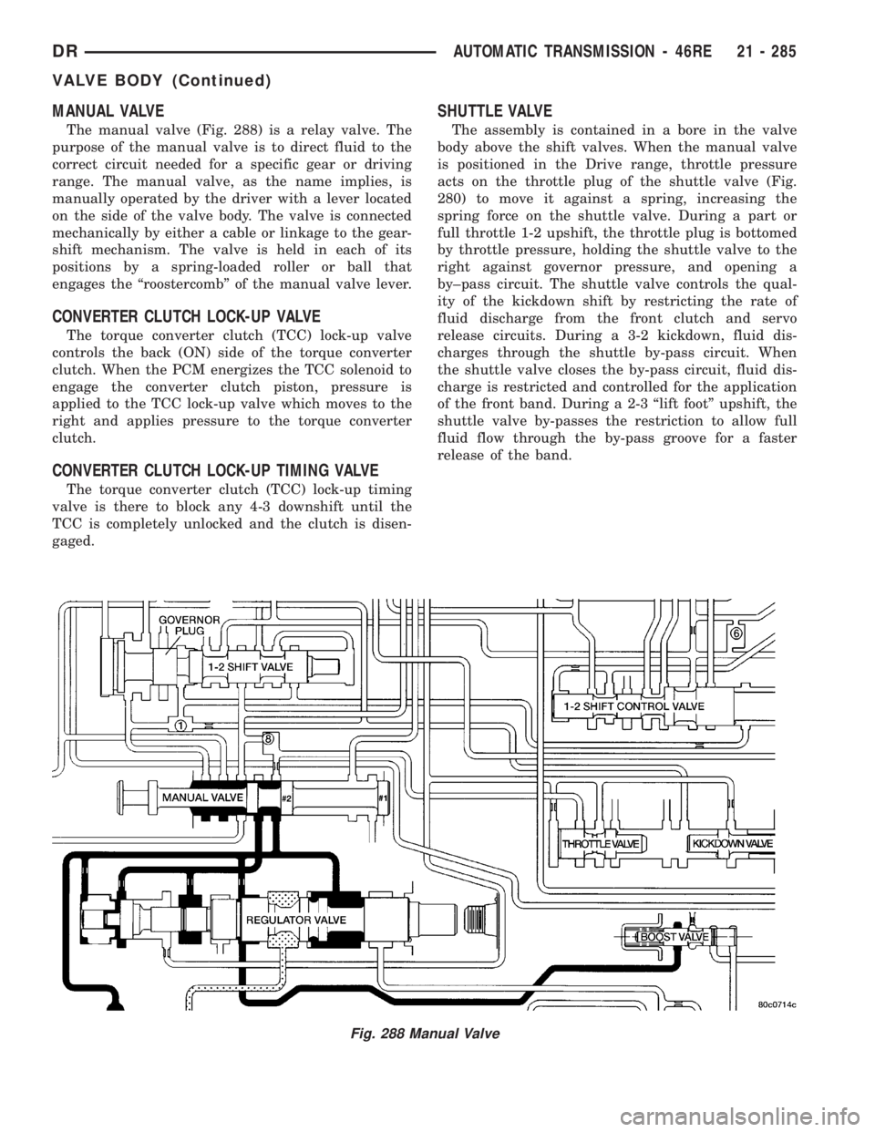
The manual valve (Fig. 288) is a relay valve. The
purpose of the manual valve is to direct fluid to the
correct circuit needed for a specific gear or driving
range. The manual valve, as the name implies, is
manually operated by the driver with a lever located
on the side of the valve body. The valve is connected
mechanically by either a cable or linkage to the gear-
shift mechanism. The valve is held in each of its
positions by a spring-loaded roller or ball that
engages the ªroostercombº of the manual valve lever.
CONVERTER CLUTCH LOCK-UP VALVE
The torque converter clutch (TCC) lock-up valve
controls the back (ON) side of the torque converter
clutch. When the PCM energizes the TCC solenoid to
engage the converter clutch piston, pressure is
applied to the TCC lock-up valve which moves to the
right and applies pressure to the torque converter
clutch.
CONVERTER CLUTCH LOCK-UP TIMING VALVE
The torque converter clutch (TCC) lock-up timing
valve is there to block any 4-3 downshift until the
TCC is completely unlocked and the clutch is disen-
gaged.
SHUTTLE VALVE
The assembly is contained in a bore in the valve
body above the shift valves. When the manual valve
is positioned in the Drive range, throttle pressure
acts on the throttle plug of the shuttle valve (Fig.
280) to move it against a spring, increasing the
spring force on the shuttle valve. During a part or
full throttle 1-2 upshift, the throttle plug is bottomed
by throttle pressure, holding the shuttle valve to the
right against governor pressure, and opening a
by±pass circuit. The shuttle valve controls the qual-
ity of the kickdown shift by restricting the rate of
fluid discharge from the front clutch and servo
release circuits. During a 3-2 kickdown, fluid dis-
charges through the shuttle by-pass circuit. When
the shuttle valve closes the by-pass circuit, fluid dis-
charge is restricted and controlled for the application
of the front band. During a 2-3 ªlift footº upshift, the
shuttle valve by-passes the restriction to allow full
fluid flow through the by-pass groove for a faster
release of the band.
Fig. 288 Manual Valve
DRAUTOMATIC TRANSMISSION - 46RE 21 - 285
VALVE BODY (Continued)
Page 2173 of 2895
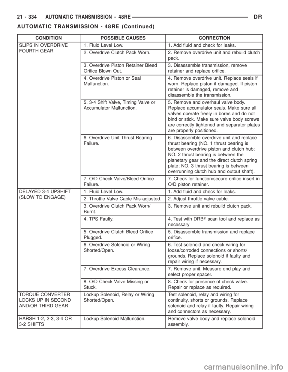
CONDITION POSSIBLE CAUSES CORRECTION
SLIPS IN OVERDRIVE
FOURTH GEAR1. Fluid Level Low. 1. Add fluid and check for leaks.
2. Overdrive Clutch Pack Worn. 2. Remove overdrive unit and rebuild clutch
pack.
3. Overdrive Piston Retainer Bleed
Orifice Blown Out.3. Disassemble transmission, remove
retainer and replace orifice.
4. Overdrive Piston or Seal
Malfunction.4. Remove overdrive unit. Replace seals if
worn. Replace piston if damaged. If piston
retainer is damaged, remove and
disassemble the transmission.
5. 3-4 Shift Valve, Timing Valve or
Accumulator Malfunction.5. Remove and overhaul valve body.
Replace accumulator seals. Make sure all
valves operate freely in bores and do not
bind or stick. Make sure valve body screws
are correctly tightened and separator plates
are properly positioned.
6. Overdrive Unit Thrust Bearing
Failure.6. Disassemble overdrive unit and replace
thrust bearing (NO. 1 thrust bearing is
between overdrive piston and clutch hub;
NO. 2 thrust bearing is between the
planetary gear and the direct clutch spring
plate; NO. 3 thrust bearing is between
overrunning clutch hub and output shaft).
7. O/D Check Valve/Bleed Orifice
Failure.7. Check for function/secure orifice insert in
O/D piston retainer.
DELAYED 3-4 UPSHIFT
(SLOW TO ENGAGE)1. Fluid Level Low. 1. Add fluid and check for leaks.
2. Throttle Valve Cable Mis-adjusted. 2. Adjust throttle valve cable.
3. Overdrive Clutch Pack Worn/
Burnt.3. Remove unit and rebuild clutch pack.
4. TPS Faulty. 4. Test with DRBTscan tool and replace as
necessary
5. Overdrive Clutch Bleed Orifice
Plugged.5. Disassemble transmission and replace
orifice.
6. Overdrive Solenoid or Wiring
Shorted/Open.6. Test solenoid and check wiring for
loose/corroded connections or shorts/
grounds. Replace solenoid if faulty and
repair wiring if necessary.
7. Overdrive Excess Clearance. 7. Remove unit. Measure end play and
select proper spacer.
8. O/D Check Valve Missing or
Stuck.8. Check for presence of check valve.
Repair or replace as required.
TORQUE CONVERTER
LOCKS UP IN SECOND
AND/OR THIRD GEARLockup Solenoid, Relay or Wiring
Shorted/Open.Test solenoid, relay and wiring for
continuity, shorts or grounds. Replace
solenoid and relay if faulty. Repair wiring
and connectors as necessary.
HARSH 1-2, 2-3, 3-4 OR
3-2 SHIFTSLockup Solenoid Malfunction. Remove valve body and replace solenoid
assembly.
21 - 334 AUTOMATIC TRANSMISSION - 48REDR
AUTOMATIC TRANSMISSION - 48RE (Continued)
Page 2216 of 2895
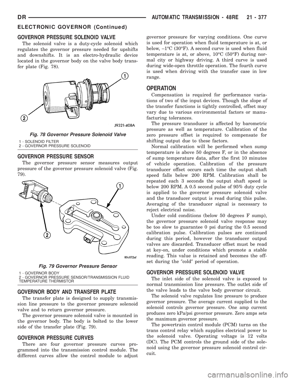
GOVERNOR PRESSURE SOLENOID VALVE
The solenoid valve is a duty-cycle solenoid which
regulates the governor pressure needed for upshifts
and downshifts. It is an electro-hydraulic device
located in the governor body on the valve body trans-
fer plate (Fig. 78).
GOVERNOR PRESSURE SENSOR
The governor pressure sensor measures output
pressure of the governor pressure solenoid valve (Fig.
79).
GOVERNOR BODY AND TRANSFER PLATE
The transfer plate is designed to supply transmis-
sion line pressure to the governor pressure solenoid
valve and to return governor pressure.
The governor pressure solenoid valve is mounted in
the governor body. The body is bolted to the lower
side of the transfer plate (Fig. 79).
GOVERNOR PRESSURE CURVES
There are four governor pressure curves pro-
grammed into the transmission control module. The
different curves allow the control module to adjustgovernor pressure for varying conditions. One curve
is used for operation when fluid temperature is at, or
below, ±1ÉC (30ÉF). A second curve is used when fluid
temperature is at, or above, 10ÉC (50ÉF) during nor-
mal city or highway driving. A third curve is used
during wide-open throttle operation. The fourth curve
is used when driving with the transfer case in low
range.
OPERATION
Compensation is required for performance varia-
tions of two of the input devices. Though the slope of
the transfer functions is tightly controlled, offset may
vary due to various environmental factors or manu-
facturing tolerances.
The pressure transducer is affected by barometric
pressure as well as temperature. Calibration of the
zero pressure offset is required to compensate for
shifting output due to these factors.
Normal calibration will be performed when sump
temperature is above 50 degrees F, or in the absence
of sump temperature data, after the first 10 minutes
of vehicle operation. Calibration of the pressure
transducer offset occurs each time the output shaft
speed falls below 200 RPM. Calibration shall be
repeated each 3 seconds the output shaft speed is
below 200 RPM. A 0.5 second pulse of 95% duty cycle
is applied to the governor pressure solenoid valve
and the transducer output is read during this pulse.
Averaging of the transducer signal is necessary to
reject electrical noise.
Under cold conditions (below 50 degrees F sump),
the governor pressure solenoid valve response may
be too slow to guarantee 0 psi during the 0.5 second
calibration pulse. Calibration pulses are continued
during this period, however the transducer output
valves are discarded. Transducer offset must be read
at key-on, under conditions which promote a stable
reading. This value is retained and becomes the off-
set during the9cold9period of operation.
GOVERNOR PRESSURE SOLENOID VALVE
The inlet side of the solenoid valve is exposed to
normal transmission line pressure. The outlet side of
the valve leads to the valve body governor circuit.
The solenoid valve regulates line pressure to produce
governor pressure. The average current supplied to the
solenoid controls governor pressure. One amp current
produces zero kPa/psi governor pressure. Zero amps sets
the maximum governor pressure.
The powertrain control module (PCM) turns on the
trans control relay which supplies electrical power to
the solenoid valve. Operating voltage is 12 volts
(DC). The PCM controls the ground side of the sole-
noid using the governor pressure solenoid control cir-
cuit.
Fig. 78 Governor Pressure Solenoid Valve
1 - SOLENOID FILTER
2 - GOVERNOR PRESSURE SOLENOID
Fig. 79 Governor Pressure Sensor
1 - GOVERNOR BODY
2 - GOVERNOR PRESSURE SENSOR/TRANSMISSION FLUID
TEMPERATURE THERMISTOR
DRAUTOMATIC TRANSMISSION - 48RE 21 - 377
ELECTRONIC GOVERNOR (Continued)
Page 2280 of 2895
TRANSMISSION RANGE
SENSOR
DESCRIPTION
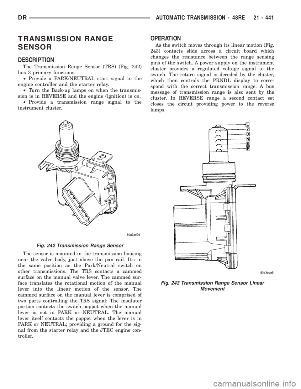
The Transmission Range Sensor (TRS) (Fig. 242)
has 3 primary functions:
²Provide a PARK/NEUTRAL start signal to the
engine controller and the starter relay.
²Turn the Back-up lamps on when the transmis-
sion is in REVERSE and the engine (ignition) is on.
²Provide a transmission range signal to the
instrument cluster.
The sensor is mounted in the transmission housing
near the valve body, just above the pan rail. It's in
the same position as the Park/Neutral switch on
other transmissions. The TRS contacts a cammed
surface on the manual valve lever. The cammed sur-
face translates the rotational motion of the manual
lever into the linear motion of the sensor. The
cammed surface on the manual lever is comprised of
two parts controlling the TRS signal: The insulator
portion contacts the switch poppet when the manual
lever is not in PARK or NEUTRAL. The manual
lever itself contacts the poppet when the lever is in
PARK or NEUTRAL; providing a ground for the sig-
nal from the starter relay and the JTEC engine con-
troller.
OPERATION
As the switch moves through its linear motion (Fig.
243) contacts slide across a circuit board which
changes the resistance between the range sensing
pins of the switch. A power supply on the instrument
cluster provides a regulated voltage signal to the
switch. The return signal is decoded by the cluster,
which then controls the PRNDL display to corre-
spond with the correct transmission range. A bus
message of transmission range is also sent by the
cluster. In REVERSE range a second contact set
closes the circuit providing power to the reverse
lamps.
Fig. 242 Transmission Range Sensor
Fig. 243 Transmission Range Sensor Linear
Movement
DRAUTOMATIC TRANSMISSION - 48RE 21 - 441
Page 2296 of 2895
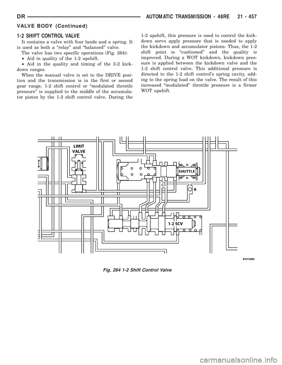
1-2 SHIFT CONTROL VALVE
It contains a valve with four lands and a spring. It
is used as both a ªrelayº and ªbalancedº valve.
The valve has two specific operations (Fig. 264):
²Aid in quality of the 1-2 upshift.
²Aid in the quality and timing of the 3-2 kick-
down ranges.
When the manual valve is set to the DRIVE posi-
tion and the transmission is in the first or second
gear range, 1-2 shift control or ªmodulated throttle
pressureº is supplied to the middle of the accumula-
tor piston by the 1-2 shift control valve. During the1-2 upshift, this pressure is used to control the kick-
down servo apply pressure that is needed to apply
the kickdown and accumulator pistons. Thus, the 1-2
shift point is ªcushionedº and the quality is
improved. During a WOT kickdown, kickdown pres-
sure is applied between the kickdown valve and the
1-2 shift control valve. This additional pressure is
directed to the 1-2 shift control's spring cavity, add-
ing to the spring load on the valve. The result of this
increased ªmodulatedº throttle pressure is a firmer
WOT upshift.
Fig. 264 1-2 Shift Control Valve
DRAUTOMATIC TRANSMISSION - 48RE 21 - 457
VALVE BODY (Continued)
Page 2302 of 2895
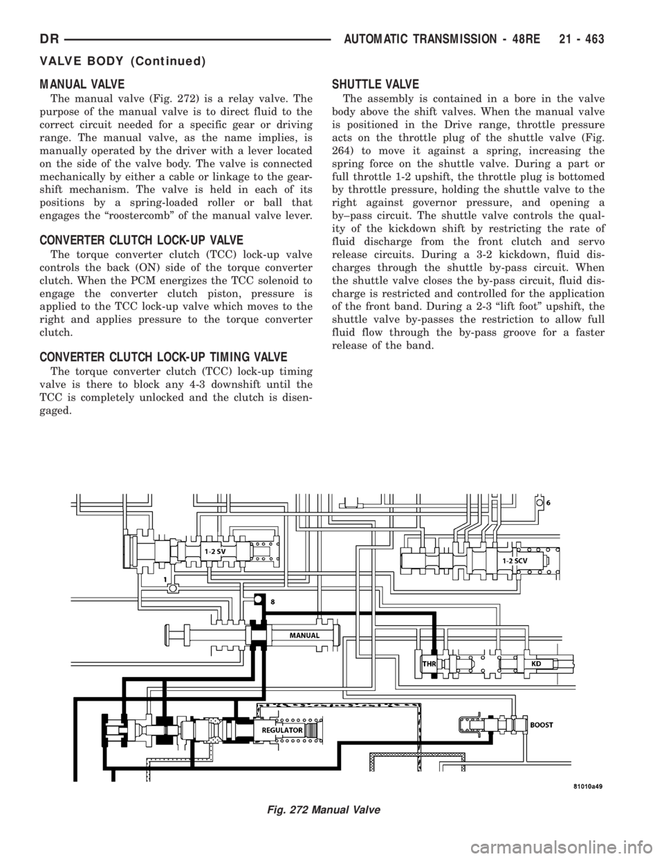
MANUAL VALVE
The manual valve (Fig. 272) is a relay valve. The
purpose of the manual valve is to direct fluid to the
correct circuit needed for a specific gear or driving
range. The manual valve, as the name implies, is
manually operated by the driver with a lever located
on the side of the valve body. The valve is connected
mechanically by either a cable or linkage to the gear-
shift mechanism. The valve is held in each of its
positions by a spring-loaded roller or ball that
engages the ªroostercombº of the manual valve lever.
CONVERTER CLUTCH LOCK-UP VALVE
The torque converter clutch (TCC) lock-up valve
controls the back (ON) side of the torque converter
clutch. When the PCM energizes the TCC solenoid to
engage the converter clutch piston, pressure is
applied to the TCC lock-up valve which moves to the
right and applies pressure to the torque converter
clutch.
CONVERTER CLUTCH LOCK-UP TIMING VALVE
The torque converter clutch (TCC) lock-up timing
valve is there to block any 4-3 downshift until the
TCC is completely unlocked and the clutch is disen-
gaged.
SHUTTLE VALVE
The assembly is contained in a bore in the valve
body above the shift valves. When the manual valve
is positioned in the Drive range, throttle pressure
acts on the throttle plug of the shuttle valve (Fig.
264) to move it against a spring, increasing the
spring force on the shuttle valve. During a part or
full throttle 1-2 upshift, the throttle plug is bottomed
by throttle pressure, holding the shuttle valve to the
right against governor pressure, and opening a
by±pass circuit. The shuttle valve controls the qual-
ity of the kickdown shift by restricting the rate of
fluid discharge from the front clutch and servo
release circuits. During a 3-2 kickdown, fluid dis-
charges through the shuttle by-pass circuit. When
the shuttle valve closes the by-pass circuit, fluid dis-
charge is restricted and controlled for the application
of the front band. During a 2-3 ªlift footº upshift, the
shuttle valve by-passes the restriction to allow full
fluid flow through the by-pass groove for a faster
release of the band.
Fig. 272 Manual Valve
DRAUTOMATIC TRANSMISSION - 48RE 21 - 463
VALVE BODY (Continued)
Page 2328 of 2895
OIL PUMP FRONT SEAL
REMOVAL............................567
INSTALLATION........................567
OUTPUT SPEED SENSOR
DESCRIPTION........................567
OPERATION..........................567
REMOVAL............................567
INSTALLATION........................567
OVERDRIVE SWITCH
DESCRIPTION........................568
OPERATION..........................568
REMOVAL............................568
INSTALLATION........................569
PISTONS
DESCRIPTION........................569
OPERATION..........................569
PLANETARY GEARTRAIN
DESCRIPTION........................571
OPERATION..........................571
DISASSEMBLY........................573
CLEANING...........................573
INSPECTION.........................573
ASSEMBLY...........................573
SHIFT MECHANISM
DESCRIPTION........................574
OPERATION..........................574
SOLENOID SWITCH VALVE
DESCRIPTION........................574
OPERATION..........................574
SOLENOIDS
DESCRIPTION........................574OPERATION..........................575
TORQUE CONVERTER
DESCRIPTION........................575
OPERATION..........................579
REMOVAL............................580
INSTALLATION........................580
TRANSMISSION CONTROL RELAY
DESCRIPTION........................581
OPERATION..........................581
TRANSMISSION RANGE SENSOR
DESCRIPTION........................581
OPERATION..........................581
TRANSMISSION SOLENOID/TRS ASSEMBLY
DESCRIPTION........................582
OPERATION..........................582
REMOVAL............................583
INSTALLATION........................583
TRANSMISSION TEMPERATURE SENSOR
DESCRIPTION........................583
OPERATION..........................583
VALVE BODY
DESCRIPTION........................584
OPERATION..........................585
REMOVAL............................585
DISASSEMBLY........................586
CLEANING...........................588
INSPECTION.........................588
ASSEMBLY...........................590
INSTALLATION........................590
AUTOMATIC TRANSMISSION -
45RFE/545RFE
DESCRIPTION
The 45RFE/545RFE automatic transmissions is a
sophisticated, multi-range, electronically controlled
transmission which combines optimized gear ratios
for responsive performance, state of the art efficiency
features and low NVH. Other features include driver
adaptive shifting and three planetary gear sets to
provide wide ratio capability with precise ratio steps
for optimum driveability. The three planetary gear
sets also make available a unique alternate second
gear ratio. The primary 2nd gear ratio fits between
1st and 3rd gears for normal through-gear accelera-
tions. The alternate second gear ratio (2prime) allows
smoother 4-2 kickdowns at high speeds to provide
2nd gear passing performance over a wider highway
cruising range.
The hydraulic portion of the transmission consists
of the transmission fluid, fluid passages, hydraulic
valves, and various line pressure control components.The primary mechanical components of the trans-
mission consist of the following:
²Three multiple disc input clutches
²Three multiple disc holding clutches
²Five hydraulic accumulators
²Three planetary gear sets
²Dual Stage Hydraulic oil pump
²Valve body
²Solenoid pack
The TCM is the ªheartº or ªbrainº of the electronic
control system and relies on information from vari-
ous direct and indirect inputs (sensors, switches, etc.)
to determine driver demand and vehicle operating
conditions. With this information, the TCM can cal-
culate and perform timely and quality shifts through
various output or control devices (solenoid pack,
transmission control relay, etc.).
TRANSMISSION IDENTIFICATION
Transmission identification numbers are stamped
on the left side of the case just above the oil pan
sealing surface (Fig. 1). Refer to this information
when ordering replacement parts. A label is attached
to the transmission case above the stamped numbers.
DRAUTOMATIC TRANSMISSION - 45RFE/545RFE 21 - 489
Page 2420 of 2895
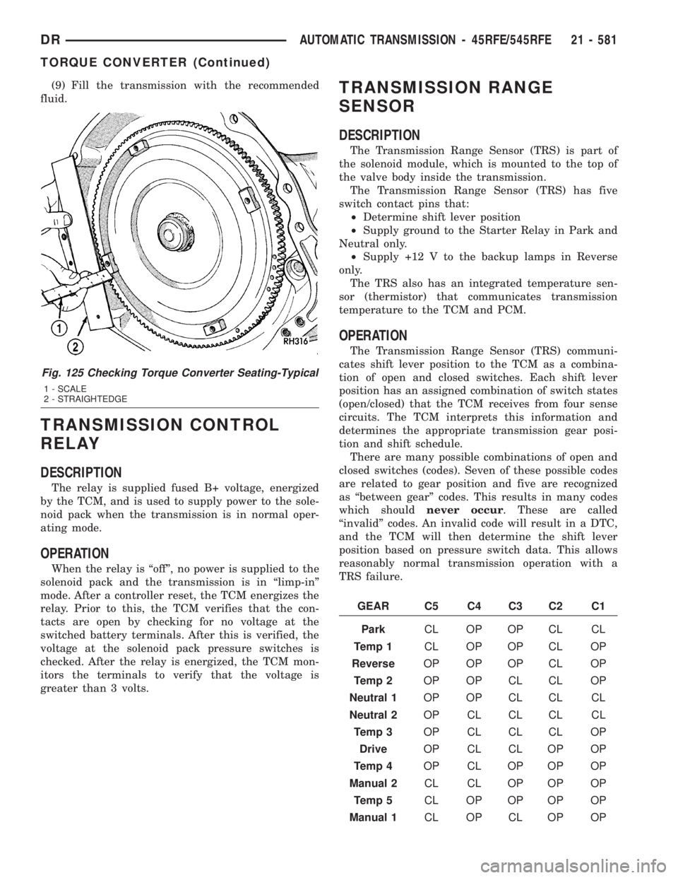
(9) Fill the transmission with the recommended
fluid.
TRANSMISSION CONTROL
RELAY
DESCRIPTION
The relay is supplied fused B+ voltage, energized
by the TCM, and is used to supply power to the sole-
noid pack when the transmission is in normal oper-
ating mode.
OPERATION
When the relay is ªoffº, no power is supplied to the
solenoid pack and the transmission is in ªlimp-inº
mode. After a controller reset, the TCM energizes the
relay. Prior to this, the TCM verifies that the con-
tacts are open by checking for no voltage at the
switched battery terminals. After this is verified, the
voltage at the solenoid pack pressure switches is
checked. After the relay is energized, the TCM mon-
itors the terminals to verify that the voltage is
greater than 3 volts.
TRANSMISSION RANGE
SENSOR
DESCRIPTION
The Transmission Range Sensor (TRS) is part of
the solenoid module, which is mounted to the top of
the valve body inside the transmission.
The Transmission Range Sensor (TRS) has five
switch contact pins that:
²Determine shift lever position
²Supply ground to the Starter Relay in Park and
Neutral only.
²Supply +12 V to the backup lamps in Reverse
only.
The TRS also has an integrated temperature sen-
sor (thermistor) that communicates transmission
temperature to the TCM and PCM.
OPERATION
The Transmission Range Sensor (TRS) communi-
cates shift lever position to the TCM as a combina-
tion of open and closed switches. Each shift lever
position has an assigned combination of switch states
(open/closed) that the TCM receives from four sense
circuits. The TCM interprets this information and
determines the appropriate transmission gear posi-
tion and shift schedule.
There are many possible combinations of open and
closed switches (codes). Seven of these possible codes
are related to gear position and five are recognized
as ªbetween gearº codes. This results in many codes
which shouldnever occur. These are called
ªinvalidº codes. An invalid code will result in a DTC,
and the TCM will then determine the shift lever
position based on pressure switch data. This allows
reasonably normal transmission operation with a
TRS failure.
GEAR C5 C4 C3 C2 C1
ParkCL OP OP CL CL
Temp 1CL OP OP CL OP
ReverseOP OP OP CL OP
Temp 2OP OP CL CL OP
Neutral 1OP OP CL CL CL
Neutral 2OP CL CL CL CL
Temp 3OP CL CL CL OP
DriveOP CL CL OP OP
Temp 4OP CL OP OP OP
Manual 2CL CL OP OP OP
Temp 5CL OP OP OP OP
Manual 1CL OP CL OP OP
Fig. 125 Checking Torque Converter Seating-Typical
1 - SCALE
2 - STRAIGHTEDGE
DRAUTOMATIC TRANSMISSION - 45RFE/545RFE 21 - 581
TORQUE CONVERTER (Continued)