2003 DODGE RAM instrument cluster
[x] Cancel search: instrument clusterPage 1050 of 2895
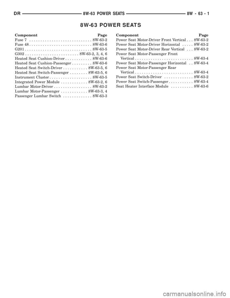
8W-63 POWER SEATS
Component Page
Fuse 7............................ 8W-63-2
Fuse 48............................ 8W-63-6
G201.............................. 8W-63-5
G302........................ 8W-63-2, 3, 4, 6
Heated Seat Cushion-Driver............ 8W-63-6
Heated Seat Cushion-Passenger......... 8W-63-6
Heated Seat Switch-Driver........... 8W-63-5, 6
Heated Seat Switch-Passenger........ 8W-63-5, 6
Instrument Cluster................... 8W-63-5
Integrated Power Module............ 8W-63-2, 6
Lumbar Motor-Driver................. 8W-63-2
Lumbar Motor-Passenger............ 8W-63-3, 4
Passenger Lumbar Switch............. 8W-63-3Component Page
Power Seat Motor-Driver Front Vertical . . . 8W-63-2
Power Seat Motor-Driver Horizontal..... 8W-63-2
Power Seat Motor-Driver Rear Vertical . . . 8W-63-2
Power Seat Motor-Passenger Front
Vertical.......................... 8W-63-4
Power Seat Motor-Passenger Horizontal . . 8W-63-4
Power Seat Motor-Passenger Rear
Vertical.......................... 8W-63-4
Power Seat Switch-Driver............. 8W-63-2
Power Seat Switch-Passenger........... 8W-63-4
Seat Heater Interface Module.......... 8W-63-6
DR8W-63 POWER SEATS 8W - 63 - 1
Page 1070 of 2895
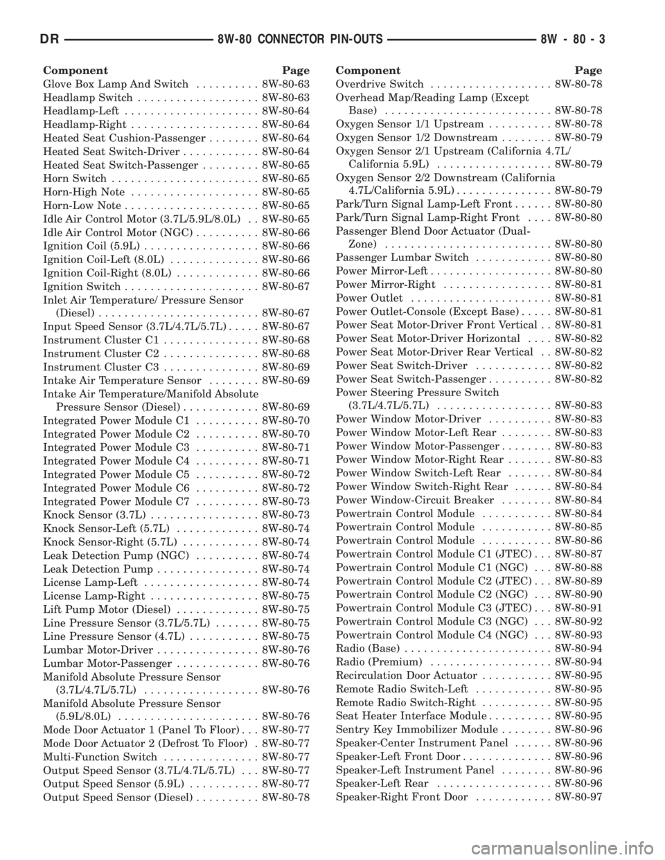
Component Page
Glove Box Lamp And Switch.......... 8W-80-63
Headlamp Switch................... 8W-80-63
Headlamp-Left..................... 8W-80-64
Headlamp-Right.................... 8W-80-64
Heated Seat Cushion-Passenger........ 8W-80-64
Heated Seat Switch-Driver............ 8W-80-64
Heated Seat Switch-Passenger......... 8W-80-65
Horn Switch....................... 8W-80-65
Horn-High Note.................... 8W-80-65
Horn-Low Note..................... 8W-80-65
Idle Air Control Motor (3.7L/5.9L/8.0L) . . 8W-80-65
Idle Air Control Motor (NGC).......... 8W-80-66
Ignition Coil (5.9L).................. 8W-80-66
Ignition Coil-Left (8.0L).............. 8W-80-66
Ignition Coil-Right (8.0L)............. 8W-80-66
Ignition Switch..................... 8W-80-67
Inlet Air Temperature/ Pressure Sensor
(Diesel)......................... 8W-80-67
Input Speed Sensor (3.7L/4.7L/5.7L)..... 8W-80-67
Instrument Cluster C1............... 8W-80-68
Instrument Cluster C2............... 8W-80-68
Instrument Cluster C3............... 8W-80-69
Intake Air Temperature Sensor........ 8W-80-69
Intake Air Temperature/Manifold Absolute
Pressure Sensor (Diesel)............ 8W-80-69
Integrated Power Module C1.......... 8W-80-70
Integrated Power Module C2.......... 8W-80-70
Integrated Power Module C3.......... 8W-80-71
Integrated Power Module C4.......... 8W-80-71
Integrated Power Module C5.......... 8W-80-72
Integrated Power Module C6.......... 8W-80-72
Integrated Power Module C7.......... 8W-80-73
Knock Sensor (3.7L)................. 8W-80-73
Knock Sensor-Left (5.7L)............. 8W-80-74
Knock Sensor-Right (5.7L)............ 8W-80-74
Leak Detection Pump (NGC).......... 8W-80-74
Leak Detection Pump................ 8W-80-74
License Lamp-Left.................. 8W-80-74
License Lamp-Right................. 8W-80-75
Lift Pump Motor (Diesel)............. 8W-80-75
Line Pressure Sensor (3.7L/5.7L)....... 8W-80-75
Line Pressure Sensor (4.7L)........... 8W-80-75
Lumbar Motor-Driver................ 8W-80-76
Lumbar Motor-Passenger............. 8W-80-76
Manifold Absolute Pressure Sensor
(3.7L/4.7L/5.7L).................. 8W-80-76
Manifold Absolute Pressure Sensor
(5.9L/8.0L)...................... 8W-80-76
Mode Door Actuator 1 (Panel To Floor) . . . 8W-80-77
Mode Door Actuator 2 (Defrost To Floor) . 8W-80-77
Multi-Function Switch............... 8W-80-77
Output Speed Sensor (3.7L/4.7L/5.7L) . . . 8W-80-77
Output Speed Sensor (5.9L)........... 8W-80-77
Output Speed Sensor (Diesel).......... 8W-80-78Component Page
Overdrive Switch................... 8W-80-78
Overhead Map/Reading Lamp (Except
Base).......................... 8W-80-78
Oxygen Sensor 1/1 Upstream.......... 8W-80-78
Oxygen Sensor 1/2 Downstream........ 8W-80-79
Oxygen Sensor 2/1 Upstream (California 4.7L/
California 5.9L).................. 8W-80-79
Oxygen Sensor 2/2 Downstream (California
4.7L/California 5.9L)............... 8W-80-79
Park/Turn Signal Lamp-Left Front...... 8W-80-80
Park/Turn Signal Lamp-Right Front.... 8W-80-80
Passenger Blend Door Actuator (Dual-
Zone).......................... 8W-80-80
Passenger Lumbar Switch............ 8W-80-80
Power Mirror-Left................... 8W-80-80
Power Mirror-Right................. 8W-80-81
Power Outlet...................... 8W-80-81
Power Outlet-Console (Except Base)..... 8W-80-81
Power Seat Motor-Driver Front Vertical . . 8W-80-81
Power Seat Motor-Driver Horizontal.... 8W-80-82
Power Seat Motor-Driver Rear Vertical . . 8W-80-82
Power Seat Switch-Driver............ 8W-80-82
Power Seat Switch-Passenger.......... 8W-80-82
Power Steering Pressure Switch
(3.7L/4.7L/5.7L).................. 8W-80-83
Power Window Motor-Driver.......... 8W-80-83
Power Window Motor-Left Rear........ 8W-80-83
Power Window Motor-Passenger........ 8W-80-83
Power Window Motor-Right Rear....... 8W-80-83
Power Window Switch-Left Rear....... 8W-80-84
Power Window Switch-Right Rear...... 8W-80-84
Power Window-Circuit Breaker........ 8W-80-84
Powertrain Control Module........... 8W-80-84
Powertrain Control Module........... 8W-80-85
Powertrain Control Module........... 8W-80-86
Powertrain Control Module C1 (JTEC) . . . 8W-80-87
Powertrain Control Module C1 (NGC) . . . 8W-80-88
Powertrain Control Module C2 (JTEC) . . . 8W-80-89
Powertrain Control Module C2 (NGC) . . . 8W-80-90
Powertrain Control Module C3 (JTEC) . . . 8W-80-91
Powertrain Control Module C3 (NGC) . . . 8W-80-92
Powertrain Control Module C4 (NGC) . . . 8W-80-93
Radio (Base)....................... 8W-80-94
Radio (Premium)................... 8W-80-94
Recirculation Door Actuator........... 8W-80-95
Remote Radio Switch-Left............ 8W-80-95
Remote Radio Switch-Right........... 8W-80-95
Seat Heater Interface Module.......... 8W-80-95
Sentry Key Immobilizer Module........ 8W-80-96
Speaker-Center Instrument Panel...... 8W-80-96
Speaker-Left Front Door.............. 8W-80-96
Speaker-Left Instrument Panel........ 8W-80-96
Speaker-Left Rear.................. 8W-80-96
Speaker-Right Front Door............ 8W-80-97
DR8W-80 CONNECTOR PIN-OUTS 8W - 80 - 3
Page 1135 of 2895
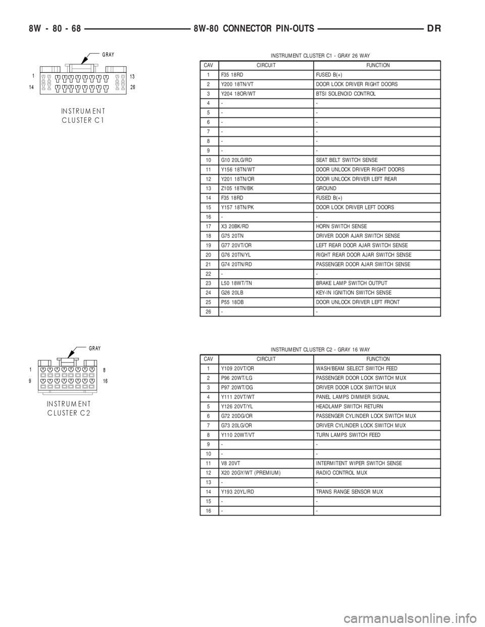
INSTRUMENT CLUSTER C1 - GRAY 26 WAY
CAV CIRCUIT FUNCTION
1 F35 18RD FUSED B(+)
2 Y200 18TN/VT DOOR LOCK DRIVER RIGHT DOORS
3 Y204 18OR/WT BTSI SOLENOID CONTROL
4- -
5- -
6- -
7- -
8- -
9- -
10 G10 20LG/RD SEAT BELT SWITCH SENSE
11 Y156 18TN/WT DOOR UNLOCK DRIVER RIGHT DOORS
12 Y201 18TN/OR DOOR UNLOCK DRIVER LEFT REAR
13 Z105 18TN/BK GROUND
14 F35 18RD FUSED B(+)
15 Y157 18TN/PK DOOR LOCK DRIVER LEFT DOORS
16 - -
17 X3 20BK/RD HORN SWITCH SENSE
18 G75 20TN DRIVER DOOR AJAR SWITCH SENSE
19 G77 20VT/OR LEFT REAR DOOR AJAR SWITCH SENSE
20 G76 20TN/YL RIGHT REAR DOOR AJAR SWITCH SENSE
21 G74 20TN/RD PASSENGER DOOR AJAR SWITCH SENSE
22 - -
23 L50 18WT/TN BRAKE LAMP SWITCH OUTPUT
24 G26 20LB KEY-IN IGNITION SWITCH SENSE
25 P55 18DB DOOR UNLOCK DRIVER LEFT FRONT
26 - -
INSTRUMENT CLUSTER C2 - GRAY 16 WAY
CAV CIRCUIT FUNCTION
1 Y109 20VT/OR WASH/BEAM SELECT SWITCH FEED
2 P96 20WT/LG PASSENGER DOOR LOCK SWITCH MUX
3 P97 20WT/DG DRIVER DOOR LOCK SWITCH MUX
4 Y111 20VT/WT PANEL LAMPS DIMMER SIGNAL
5 Y126 20VT/YL HEADLAMP SWITCH RETURN
6 G72 20DG/OR PASSENGER CYLINDER LOCK SWITCH MUX
7 G73 20LG/OR DRIVER CYLINDER LOCK SWITCH MUX
8 Y110 20WT/VT TURN LAMPS SWITCH FEED
9- -
10 - -
11 V8 20VT INTERMITENT WIPER SWITCH SENSE
12 X20 20GY/WT (PREMIUM) RADIO CONTROL MUX
13 - -
14 Y193 20YL/RD TRANS RANGE SENSOR MUX
15 - -
16 - -
8W - 80 - 68 8W-80 CONNECTOR PIN-OUTSDR
Page 1136 of 2895
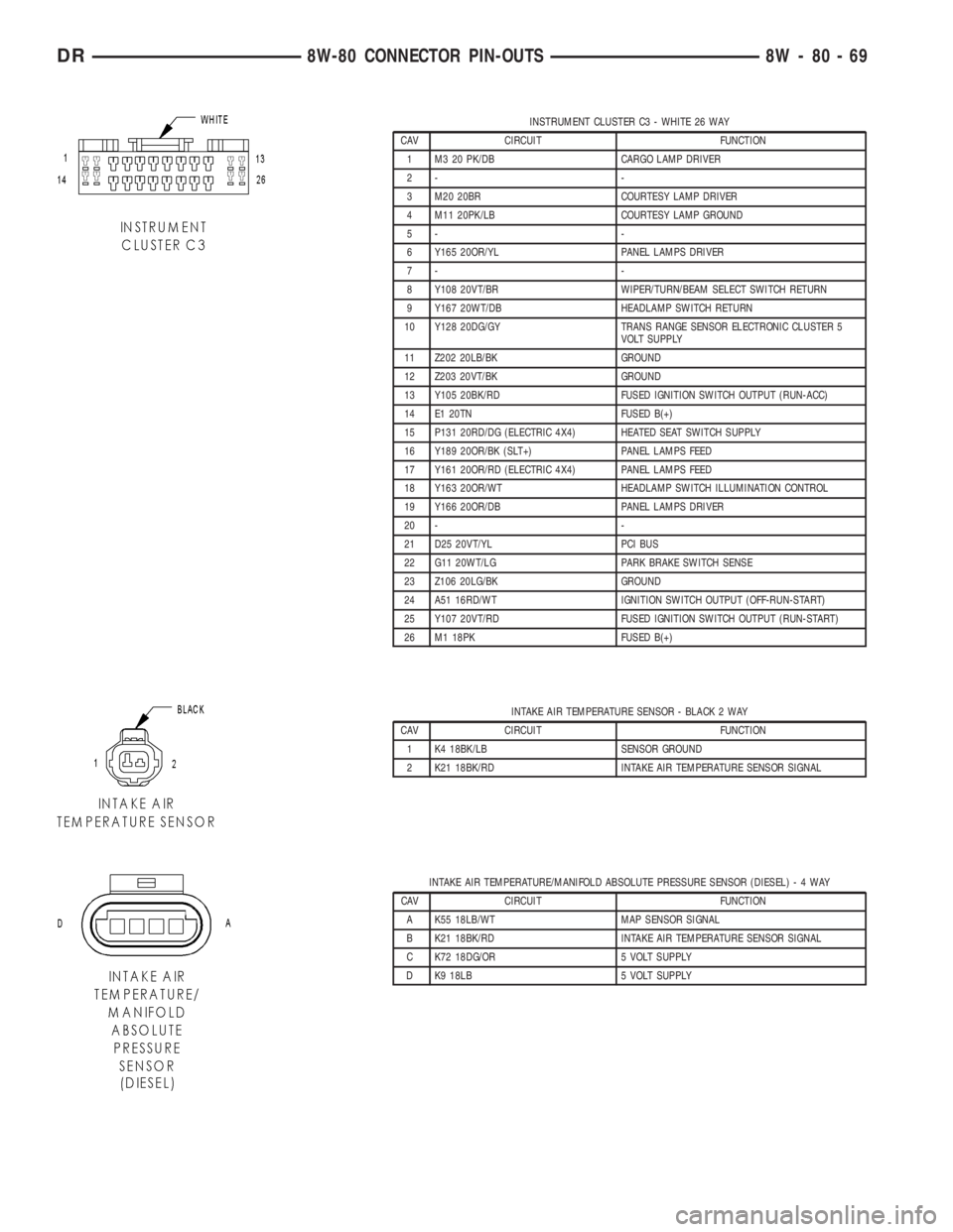
INSTRUMENT CLUSTER C3 - WHITE 26 WAY
CAV CIRCUIT FUNCTION
1 M3 20 PK/DB CARGO LAMP DRIVER
2- -
3 M20 20BR COURTESY LAMP DRIVER
4 M11 20PK/LB COURTESY LAMP GROUND
5- -
6 Y165 20OR/YL PANEL LAMPS DRIVER
7- -
8 Y108 20VT/BR WIPER/TURN/BEAM SELECT SWITCH RETURN
9 Y167 20WT/DB HEADLAMP SWITCH RETURN
10 Y128 20DG/GY TRANS RANGE SENSOR ELECTRONIC CLUSTER 5
VOLT SUPPLY
11 Z202 20LB/BK GROUND
12 Z203 20VT/BK GROUND
13 Y105 20BK/RD FUSED IGNITION SWITCH OUTPUT (RUN-ACC)
14 E1 20TN FUSED B(+)
15 P131 20RD/DG (ELECTRIC 4X4) HEATED SEAT SWITCH SUPPLY
16 Y189 20OR/BK (SLT+) PANEL LAMPS FEED
17 Y161 20OR/RD (ELECTRIC 4X4) PANEL LAMPS FEED
18 Y163 20OR/WT HEADLAMP SWITCH ILLUMINATION CONTROL
19 Y166 20OR/DB PANEL LAMPS DRIVER
20 - -
21 D25 20VT/YL PCI BUS
22 G11 20WT/LG PARK BRAKE SWITCH SENSE
23 Z106 20LG/BK GROUND
24 A51 16RD/WT IGNITION SWITCH OUTPUT (OFF-RUN-START)
25 Y107 20VT/RD FUSED IGNITION SWITCH OUTPUT (RUN-START)
26 M1 18PK FUSED B(+)
INTAKE AIR TEMPERATURE SENSOR - BLACK 2 WAY
CAV CIRCUIT FUNCTION
1 K4 18BK/LB SENSOR GROUND
2 K21 18BK/RD INTAKE AIR TEMPERATURE SENSOR SIGNAL
INTAKE AIR TEMPERATURE/MANIFOLD ABSOLUTE PRESSURE SENSOR (DIESEL)-4WAY
CAV CIRCUIT FUNCTION
A K55 18LB/WT MAP SENSOR SIGNAL
B K21 18BK/RD INTAKE AIR TEMPERATURE SENSOR SIGNAL
C K72 18DG/OR 5 VOLT SUPPLY
D K9 18LB 5 VOLT SUPPLY
DR8W-80 CONNECTOR PIN-OUTS 8W - 80 - 69
Page 1182 of 2895
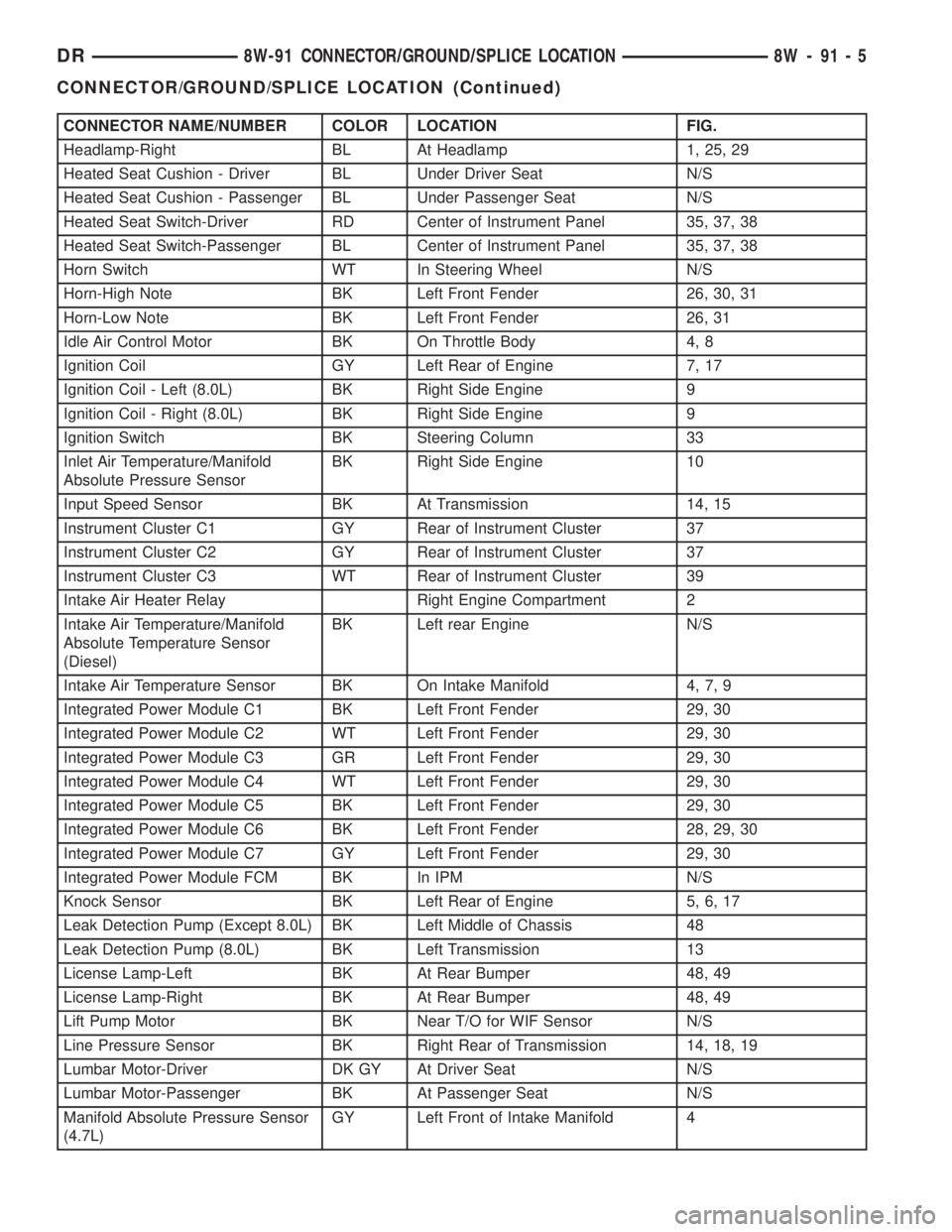
CONNECTOR NAME/NUMBER COLOR LOCATION FIG.
Headlamp-Right BL At Headlamp 1, 25, 29
Heated Seat Cushion - Driver BL Under Driver Seat N/S
Heated Seat Cushion - Passenger BL Under Passenger Seat N/S
Heated Seat Switch-Driver RD Center of Instrument Panel 35, 37, 38
Heated Seat Switch-Passenger BL Center of Instrument Panel 35, 37, 38
Horn Switch WT In Steering Wheel N/S
Horn-High Note BK Left Front Fender 26, 30, 31
Horn-Low Note BK Left Front Fender 26, 31
Idle Air Control Motor BK On Throttle Body 4, 8
Ignition Coil GY Left Rear of Engine 7, 17
Ignition Coil - Left (8.0L) BK Right Side Engine 9
Ignition Coil - Right (8.0L) BK Right Side Engine 9
Ignition Switch BK Steering Column 33
Inlet Air Temperature/Manifold
Absolute Pressure SensorBK Right Side Engine 10
Input Speed Sensor BK At Transmission 14, 15
Instrument Cluster C1 GY Rear of Instrument Cluster 37
Instrument Cluster C2 GY Rear of Instrument Cluster 37
Instrument Cluster C3 WT Rear of Instrument Cluster 39
Intake Air Heater Relay Right Engine Compartment 2
Intake Air Temperature/Manifold
Absolute Temperature Sensor
(Diesel)BK Left rear Engine N/S
Intake Air Temperature Sensor BK On Intake Manifold 4, 7, 9
Integrated Power Module C1 BK Left Front Fender 29, 30
Integrated Power Module C2 WT Left Front Fender 29, 30
Integrated Power Module C3 GR Left Front Fender 29, 30
Integrated Power Module C4 WT Left Front Fender 29, 30
Integrated Power Module C5 BK Left Front Fender 29, 30
Integrated Power Module C6 BK Left Front Fender 28, 29, 30
Integrated Power Module C7 GY Left Front Fender 29, 30
Integrated Power Module FCM BK In IPM N/S
Knock Sensor BK Left Rear of Engine 5, 6, 17
Leak Detection Pump (Except 8.0L) BK Left Middle of Chassis 48
Leak Detection Pump (8.0L) BK Left Transmission 13
License Lamp-Left BK At Rear Bumper 48, 49
License Lamp-Right BK At Rear Bumper 48, 49
Lift Pump Motor BK Near T/O for WIF Sensor N/S
Line Pressure Sensor BK Right Rear of Transmission 14, 18, 19
Lumbar Motor-Driver DK GY At Driver Seat N/S
Lumbar Motor-Passenger BK At Passenger Seat N/S
Manifold Absolute Pressure Sensor
(4.7L)GY Left Front of Intake Manifold 4
DR8W-91 CONNECTOR/GROUND/SPLICE LOCATION 8W - 91 - 5
CONNECTOR/GROUND/SPLICE LOCATION (Continued)
Page 1188 of 2895
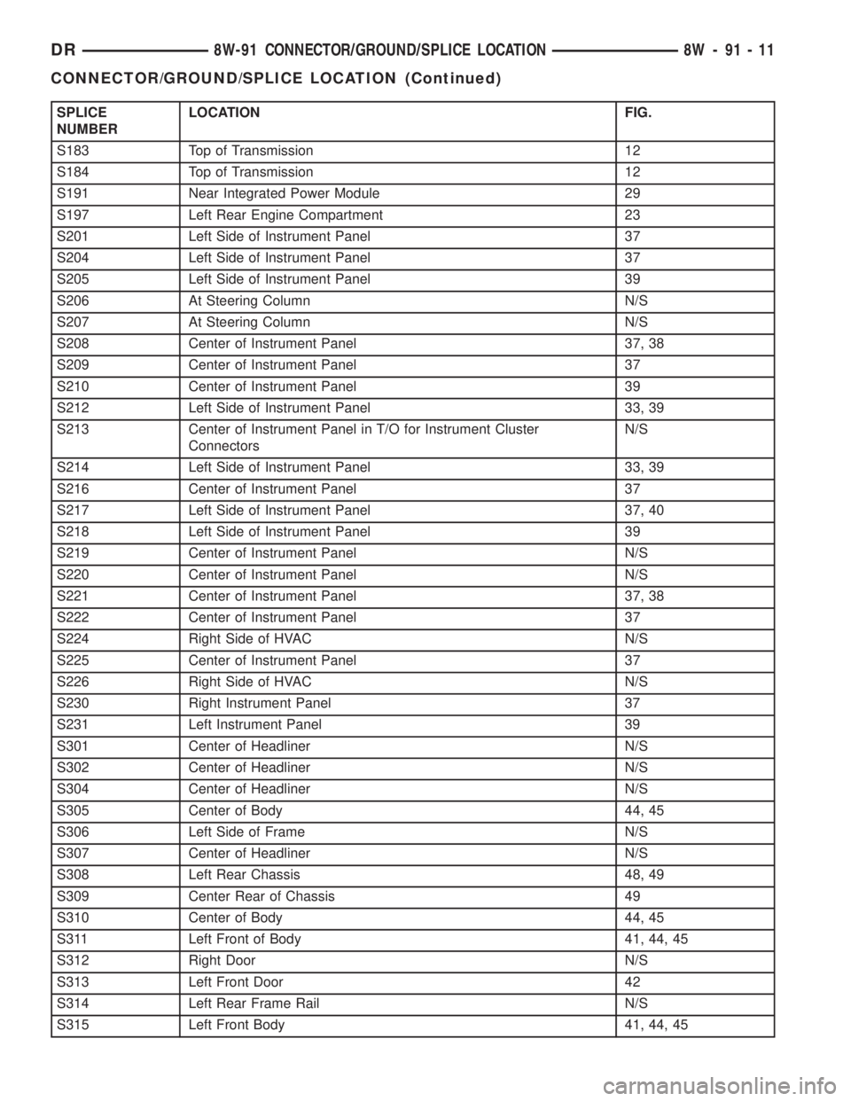
SPLICE
NUMBERLOCATION FIG.
S183 Top of Transmission 12
S184 Top of Transmission 12
S191 Near Integrated Power Module 29
S197 Left Rear Engine Compartment 23
S201 Left Side of Instrument Panel 37
S204 Left Side of Instrument Panel 37
S205 Left Side of Instrument Panel 39
S206 At Steering Column N/S
S207 At Steering Column N/S
S208 Center of Instrument Panel 37, 38
S209 Center of Instrument Panel 37
S210 Center of Instrument Panel 39
S212 Left Side of Instrument Panel 33, 39
S213 Center of Instrument Panel in T/O for Instrument Cluster
ConnectorsN/S
S214 Left Side of Instrument Panel 33, 39
S216 Center of Instrument Panel 37
S217 Left Side of Instrument Panel 37, 40
S218 Left Side of Instrument Panel 39
S219 Center of Instrument Panel N/S
S220 Center of Instrument Panel N/S
S221 Center of Instrument Panel 37, 38
S222 Center of Instrument Panel 37
S224 Right Side of HVAC N/S
S225 Center of Instrument Panel 37
S226 Right Side of HVAC N/S
S230 Right Instrument Panel 37
S231 Left Instrument Panel 39
S301 Center of Headliner N/S
S302 Center of Headliner N/S
S304 Center of Headliner N/S
S305 Center of Body 44, 45
S306 Left Side of Frame N/S
S307 Center of Headliner N/S
S308 Left Rear Chassis 48, 49
S309 Center Rear of Chassis 49
S310 Center of Body 44, 45
S311 Left Front of Body 41, 44, 45
S312 Right Door N/S
S313 Left Front Door 42
S314 Left Rear Frame Rail N/S
S315 Left Front Body 41, 44, 45
DR8W-91 CONNECTOR/GROUND/SPLICE LOCATION 8W - 91 - 11
CONNECTOR/GROUND/SPLICE LOCATION (Continued)
Page 1704 of 2895
pump.Refer to Fuel Pump - Description and
Operation for more information.
If fuel pressure at the pressure regulator exceeds
approximately 49.2 psi, an internal diaphragm opens
and excess fuel pressure is routed back into the tank
through the bottom of pressure regulator.
Both fuel filters (at bottom of fuel pump module
and within fuel pressure regulator) are designed for
extended service. They do not require normal sched-
uled maintenance. Filters should only be replaced if
a diagnostic procedure indicates to do so.
FUEL LEVEL SENDING UNIT /
SENSOR
DESCRIPTION
The fuel gauge sending unit (fuel level sensor) is
attached to the side of the fuel pump module. The
sending unit consists of a float, an arm, and a vari-
able resistor track (card).
OPERATION
The fuel pump module has 4 different circuits
(wires). Two of these circuits are used for the fuel
gauge sending unit for fuel gauge operation, and for
certain OBD II emission requirements. The other 2
wires are used for electric fuel pump operation.
For Fuel Gauge Operation:A constant current
source is supplied to the resistor track on the fuel
gauge sending unit. This is fed directly from the
Powertrain Control Module (PCM).NOTE: For
diagnostic purposes, this 12V power source can
only be verified with the circuit opened (fuel
pump module electrical connector unplugged).
With the connectors plugged, output voltages
will vary from about 0.6 volts at FULL, to about
8.6 volts at EMPTY (about 8.6 volts at EMPTY
for Jeep models, and about 7.0 volts at EMPTY
for Dodge Truck models).The resistor track is
used to vary the voltage (resistance) depending on
fuel tank float level. As fuel level increases, the float
and arm move up, which decreases voltage. As fuel
level decreases, the float and arm move down, which
increases voltage. The varied voltage signal is
returned back to the PCM through the sensor return
circuit.
Both of the electrical circuits between the fuel
gauge sending unit and the PCM are hard-wired (not
multi-plexed). After the voltage signal is sent from
the resistor track, and back to the PCM, the PCM
will interpret the resistance (voltage) data and send
a message across the multi-plex bus circuits to the
instrument panel cluster. Here it is translated into
the appropriate fuel gauge level reading. Refer to
Instrument Panel for additional information.For OBD II Emission Monitor Requirements:
The PCM will monitor the voltage output sent from
the resistor track on the sending unit to indicate fuel
level. The purpose of this feature is to prevent the
OBD II system from recording/setting false misfire
and fuel system monitor diagnostic trouble codes.
The feature is activated if the fuel level in the tank
is less than approximately 15 percent of its rated
capacity. If equipped with a Leak Detection Pump
(EVAP system monitor), this feature will also be acti-
vated if the fuel level in the tank is more than
approximately 85 percent of its rated capacity.
REMOVAL
The fuel level sending unit (fuel level sensor) and
float assembly is located on the side of the fuel pump
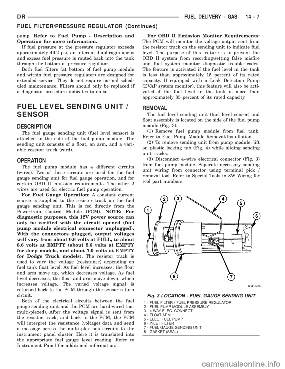
module (Fig. 3).
(1) Remove fuel pump module from fuel tank.
Refer to Fuel Pump Module Removal/Installation.
(2) To remove sending unit from pump module, lift
on plastic locking tab (Fig. 4) while sliding sending
unit tracks.
(3) Disconnect 4±wire electrical connector (Fig. 3)
from fuel pump module. Separate necessary sending
unit wiring from connector using terminal pick /
removal tool. Refer to Special Tools in 8W Wiring for
tool part numbers.
Fig. 3 LOCATION - FUEL GAUGE SENDING UNIT
1 - FUEL FILTER / FUEL PRESSURE REGULATOR
2 - FUEL PUMP MODULE ASSEMBLY
3 - 4-WAY ELEC. CONNECT.
4 - FLOAT ARM
5 - ELEC. FUEL PUMP
6 - INLET FILTER
7 - FUEL GAUGE SENDING UNIT
8 - GASKET (SEAL)
DRFUEL DELIVERY - GAS 14 - 7
FUEL FILTER/PRESSURE REGULATOR (Continued)
Page 1765 of 2895
(4) Apply clean engine oilto injection pump
o-ring only.
The machined tapers on both injection pump
shaft and injection pump gear must be abso-
lutely dry, clean and free of any dirt or oil film.
This will ensure proper gear-to-shaft tighten-
ing.
(5) Clean pump gear and pump shaft at machined
tapers with an evaporative type cleaner such as
brake cleaner.
(6) Position injection pump to mounting flange on
gear cover while aligning injection pump shaft
through back of injection pump gear.
(7) After pump is positioned flat to mounting
flange, install 3 pump mounting nuts and tighten
finger tight only.Do not attempt a final tightening
at this time.Do not attempt to tighten (pull)
pump to gear cover using mounting nuts. Dam-
age to pump or gear cover may occur. The
pump must be positioned flat to its mounting
flange before attempting to tighten 3 mounting
nuts.
(8) To prevent damage or cracking of components,
install and tighten nuts in the following sequence:
(a) Install injection pump shaft washer and nut
to pump shaft. Tighten nutfinger tight only.
(b) Do preliminary (light) tightening of injection
pump shaft nut.
(c) Tighten 3 injection pump mounting nuts to 8
N´m (70.8 in. lbs.).
(d) Do a final tightening of pump shaft nut to
105 N´m (77 ft. lbs.).
(9) Install drive gear access cover (plate) using a
1/2 inch drive ratchet. Plate is threaded to timing
gear cover.
(10) Install Engine Control Module (ECM) to left
side of engine.
(11) Install fuel line (injection pump-to-overflow
valve). Tighten bolts to 24 N´m (17 ft. lbs.) torque.
(12) Install fuel line (injection pump-to-fuel rail).
Tighten to 24 N´m (17 ft. lbs.) torque.
(13) Install fuel line (injection pump-to-fuel filter
housing). Tighten to 24 N´m (17 ft. lbs.) torque.
(14) Connect Fuel Control Actuator (FCA) electri-
cal connector to rear of injection pump.
(15) Install intake manifold air intake tube (above
injection pump). Tighten clamps.
(16) Install accessory drive belt.
(17) Install cooling fan shroud.
(18) Install cooling fan assembly.
(19) Connect both negative battery cables to both
batteries.
(20) Check system for fuel or engine oil leaks.FUEL LEVEL SENDING UNIT /
SENSOR
DESCRIPTION
The fuel gauge sending unit (fuel level sensor) is
attached to the side of the fuel tank module. The
sending unit consists of a float, an arm, and a vari-
able resistor track (card).
OPERATION
The fuel tank module on diesel powered models
has 3 different circuits (wires). Two of these circuits
are used at the fuel gauge sending unit for fuel
gauge operation. The other wire is used for a ground.
The diesel engine does not have a fuel tank module
mounted electric fuel pump. The electric fuel pump
(fuel transfer pump) is mounted to the engine.
For Fuel Gauge Operation:A constant input
voltage source of about 12 volts (battery voltage) is
supplied to the resistor track on the fuel gauge send-
ing unit. This is fed directly from the Powertrain
Control Module (PCM).NOTE: For diagnostic pur-
poses, this 12V power source can only be veri-
fied with the circuit opened (fuel tank module
electrical connector unplugged). With the con-
nectors plugged, output voltages will vary from
about .6 volts at FULL, to about 7.0 volts at
EMPTY.The resistor track is used to vary the volt-
age (resistance) depending on fuel tank float level. As
fuel level increases, the float and arm move up,
which decreases voltage. As fuel level decreases, the
float and arm move down, which increases voltage.
The varied voltage signal is returned back to the
ECM through the sensor return circuit.
Both of the electrical circuits between the fuel
gauge sending unit and the ECM are hard-wired (not
multi-plexed). After the voltage signal is sent from
the resistor track, and back to the ECM, the ECM
will interpret the resistance (voltage) data and send
a message across the multi-plex bus circuits to the
instrument panel cluster. Here it is translated into
the appropriate fuel gauge level reading. Refer to
Instrument Panel for additional information.
REMOVAL
REMOVAL/INSTALLATION
For diesel removal and installation procedures,
refer to the gas section of Fuel System/Fuel Delivery.
See Fuel Level Sending Unit/Sensor Removal/Instal-
lation.
14 - 68 FUEL DELIVERY - DIESELDR
FUEL INJECTION PUMP (Continued)