2003 DODGE RAM instrument cluster
[x] Cancel search: instrument clusterPage 681 of 2895
If the control knob is held depressed for more than
about thirty seconds, the FCM will suspend washer
pump/motor operation until the knob is released for
about two seconds, then cycled back to the Wash
position; however, the wipers will continue to operate
for as long as the Wash switch is held closed. The
FCM monitors the changing state of the wiper motor
park switch through a hard wired wiper park switch
sense circuit input. This input allows the FCM to
count the number of wipe cycles that occur after the
Wash switch is released, and to determine the proper
interval at which to de-energize the wiper on/off
relay to complete the wipe-after-wash mode cycle.
DIAGNOSIS AND TESTING - WIPER &
WASHER SYSTEM
If the wiper motor operates, but the wipers do not
move on the windshield, replace the faulty wiper
module. If the washer pump/motor operates, but no
washer fluid is dispensed on the glass; or, if the wip-
ers operate, but chatter, lift, or do not clear the glass,
clean and inspect the wiper and washer system com-
ponents as required. (Refer to 8 - ELECTRICAL/
WIPERS/WASHERS - CLEANING) and (Refer to 8 -
ELECTRICAL/WIPERS/WASHERS - INSPECTION).
For diagnosis and testing of the multi-function
switch (Refer to 8 - ELECTRICAL/LAMPS/LIGHT-
ING - EXTERIOR/MULTI-FUNCTION SWITCH -
DIAGNOSIS AND TESTING). Refer to the appropri-
ate wiring information. The wiring information
includes wiring diagrams, proper wire and connector
repair procedures, details of wire harness routing
and retention, connector pin-out information and
location views for the various wire harness connec-
tors, splices and grounds.
The hard wired circuits and components of the
wiper and washer system may be diagnosed and
tested using conventional diagnostic tools and proce-
dures. However, conventional diagnostic methods
may not prove conclusive in the diagnosis of the
instrument cluster, the Front Control Module (FCM),
or the electronic message inputs to or outputs from
the instrument cluster and the FCM that control the
various wiper and washer system operating modes.
The most reliable, efficient, and accurate means to
diagnose the instrument cluster, the FCM, or the
electronic message inputs and outputs related to the
various wiper and washer system operating modes
requires the use of a DRBIIItscan tool. Refer to the
appropriate diagnostic information.
WARNING: ON VEHICLES EQUIPPED WITH AIR-
BAGS, DISABLE THE SUPPLEMENTAL RESTRAINT
SYSTEM BEFORE ATTEMPTING ANY STEERING
WHEEL, STEERING COLUMN, DRIVER AIRBAG,
PASSENGER AIRBAG, SEAT BELT TENSIONER,SIDE CURTAIN AIRBAG, OR INSTRUMENT PANEL
COMPONENT DIAGNOSIS OR SERVICE. DISCON-
NECT AND ISOLATE THE BATTERY NEGATIVE
(GROUND) CABLE, THEN WAIT TWO MINUTES FOR
THE SYSTEM CAPACITOR TO DISCHARGE BEFORE
PERFORMING FURTHER DIAGNOSIS OR SERVICE.
THIS IS THE ONLY SURE WAY TO DISABLE THE
SUPPLEMENTAL RESTRAINT SYSTEM. FAILURE TO
TAKE THE PROPER PRECAUTIONS COULD
RESULT IN ACCIDENTAL AIRBAG DEPLOYMENT
AND POSSIBLE PERSONAL INJURY.
CLEANING - WIPER & WASHER SYSTEM
WIPER SYSTEM
The squeegees of wiper blades exposed to the ele-
ments for a long time tend to lose their wiping effec-
tiveness. Periodic cleaning of the squeegees is
suggested to remove any deposits of salt or road film.
The wiper blades, arms, and windshield glass should
only be cleaned using a sponge or soft cloth and
windshield washer fluid, a mild detergent, or a non-
abrasive cleaner. If the wiper blades continue to
leave streaks, smears, hazing, or beading on the
glass after thorough cleaning of the squeegees and
the glass, the entire wiper blade assembly must be
replaced.
CAUTION: Protect the rubber squeegees of the
wiper blades from any petroleum-based cleaners,
solvents, or contaminants. These products can rap-
idly deteriorate the rubber squeegees.
WASHER SYSTEM
If the washer system is contaminated with foreign
material, drain the washer reservoir by removing the
washer pump/motor from the reservoir. Clean foreign
material from the inside of the washer pump/motor
inlet filter screen and the washer reservoir using
clean washer fluid, a mild detergent, or a non-abra-
sive cleaner. Flush foreign material from the washer
system plumbing by first disconnecting the washer
hoses from the washer nozzles, then running the
washer pump/motor to run clean washer fluid or
water through the system. Plugged or restricted
washer nozzles should be carefully back-flushed
using compressed air. If the washer nozzle obstruc-
tion cannot be cleared, replace the washer nozzle.
CAUTION: Never introduce petroleum-based clean-
ers, solvents, or contaminants into the washer sys-
tem. These products can rapidly deteriorate the
rubber seals and hoses of the washer system, as
well as the rubber squeegees of the wiper blades.
8R - 6 WIPERS/WASHERSDR
WIPERS/WASHERS (Continued)
Page 685 of 2895

The washer fluid level switch is connected to the
vehicle electrical system through a dedicated take
out and connector of the right (except V-10 and diesel
engines) or left (V-10 and diesel engines only) head-
lamp and dash wire harness. The switch is connected
in series between a clean ground output of the Front
Control Module (FCM) on a sensor return circuit and
the washer fluid switch sense input to the FCM.
When the switch closes, the FMC senses the ground
on the washer fluid switch sense circuit. The FMC is
programmed to respond to this input by sending an
electronic washer fluid indicator lamp-on message to
the instrument cluster over the Programmable Com-
munications Interface (PCI) data bus. The instru-
ment cluster responds to this message by
illuminating the washer fluid indicator and by sound-
ing an audible chime tone warning.
The washer fluid level switch may be diagnosed
and tested using conventional diagnostic tools and
procedures. However, conventional diagnostic meth-
ods may not prove conclusive in the diagnosis of the
instrument cluster, the Front Control Module (FCM),
or the electronic message inputs to or outputs from
the instrument cluster and the FCM that control the
operation of the washer fluid visual and/or audible
indicators. The most reliable, efficient, and accurate
means to diagnose the washer fluid level indicator,
the instrument cluster, the FCM, or the electronic
message inputs and outputs related to the washer
fluid indicator requires the use of a DRBIIItscan
tool. Refer to the appropriate diagnostic information.
REMOVAL
The washer fluid level switch can be removed from
the washer reservoir without removing the reservoir
from the vehicle.
(1) Unlatch and open the hood.
(2) Disconnect and isolate the battery negative
cable.
(3) Disconnect the washer hose from the barbed
outlet nipple of the washer pump/motor unit and
allow the washer fluid to drain into a clean container
for reuse.
(4) Disconnect the right (except V-10 and diesel
engine) or left (V-10 and diesel engine only) head-
lamp and dash wire harness connector for the washer
fluid level switch from the switch connector recepta-
cle (Fig. 7) or (Fig. 8).
NOTE: The pivoting float of the washer fluid level
switch must be in a horizontal position within the
reservoir in order to be removed. With the reservoir
empty and in an upright position, the pivoting float
will orient itself to the horizontal position when the
switch connector receptacle is pointed straight
upwards.(5) Using a trim stick or another suitable wide
flat-bladed tool, gently pry the barbed nipple of the
washer fluid level switch out of the rubber grommet
seal on the reservoir sump. Care must be taken not
to damage the reservoir.
Fig. 7 Washer Fluid Level Switch Remove/Install -
Except V-10 & Diesel Engine
1 - WASHER HOSE
2 - WASHER RESERVOIR
3 - WASHER FLUID LEVEL SWITCH
4 - WIRE HARNESS
5 - WASHER PUMP/MOTOR
Fig. 8 Washer Fluid Level Switch Remove/Install -
V-10 & Diesel Engine
1 - WIRE HARNESS
2 - WASHER RESERVOIR
3 - WASHER PUMP/MOTOR
4 - WASHER HOSE
5 - WASHER FLUID LEVEL SWITCH
8R - 10 WIPERS/WASHERSDR
WASHER FLUID LEVEL SWITCH (Continued)
Page 688 of 2895
(4) Reinstall the washer hose for the washer noz-
zle into its routing clips on the underside of the cowl
plenum cover/grille panel.
(5) Reinstall the cowl plenum cover/grille panel
over the cowl plenum. (Refer to 23 - BODY/EXTERI-
OR/COWL GRILLE - INSTALLATION).
(6) Close and latch the hood.
(7) Reinstall both wiper arms onto the wiper piv-
ots. (Refer to 8 - ELECTRICAL/WIPERS/WASHERS/
WIPER ARM - INSTALLATION).
WASHER PUMP/MOTOR
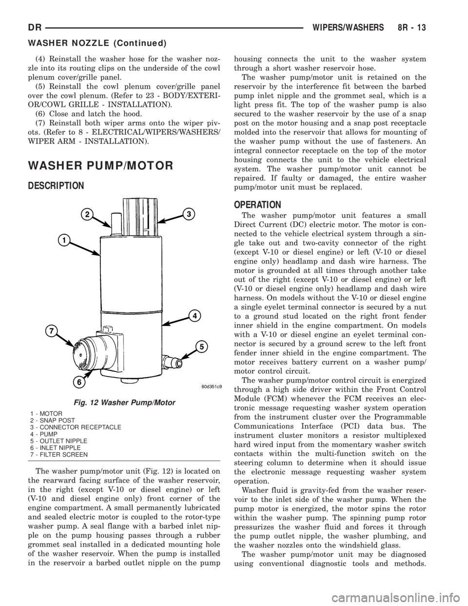
DESCRIPTION
The washer pump/motor unit (Fig. 12) is located on
the rearward facing surface of the washer reservoir,
in the right (except V-10 or diesel engine) or left
(V-10 and diesel engine only) front corner of the
engine compartment. A small permanently lubricated
and sealed electric motor is coupled to the rotor-type
washer pump. A seal flange with a barbed inlet nip-
ple on the pump housing passes through a rubber
grommet seal installed in a dedicated mounting hole
of the washer reservoir. When the pump is installed
in the reservoir a barbed outlet nipple on the pumphousing connects the unit to the washer system
through a short washer reservoir hose.
The washer pump/motor unit is retained on the
reservoir by the interference fit between the barbed
pump inlet nipple and the grommet seal, which is a
light press fit. The top of the washer pump is also
secured to the washer reservoir by the use of a snap
post on the motor housing and a snap post receptacle
molded into the reservoir that allows for mounting of
the washer pump without the use of fasteners. An
integral connector receptacle on the top of the motor
housing connects the unit to the vehicle electrical
system. The washer pump/motor unit cannot be
repaired. If faulty or damaged, the entire washer
pump/motor unit must be replaced.
OPERATION
The washer pump/motor unit features a small
Direct Current (DC) electric motor. The motor is con-
nected to the vehicle electrical system through a sin-
gle take out and two-cavity connector of the right
(except V-10 or diesel engine) or left (V-10 or diesel
engine only) headlamp and dash wire harness. The
motor is grounded at all times through another take
out of the right (except V-10 or diesel engine) or left
(V-10 or diesel engine only) headlamp and dash wire
harness. On models without the V-10 or diesel engine
a single eyelet terminal connector is secured by a nut
to a ground stud located on the right front fender
inner shield in the engine compartment. On models
with a V-10 or diesel engine an eyelet terminal con-
nector is secured by a ground screw to the left front
fender inner shield in the engine compartment. The
motor receives battery current on a washer pump/
motor control circuit.
The washer pump/motor control circuit is energized
through a high side driver within the Front Control
Module (FCM) whenever the FCM receives an elec-
tronic message requesting washer system operation
from the instrument cluster over the Programmable
Communications Interface (PCI) data bus. The
instrument cluster monitors a resistor multiplexed
hard wired input from the momentary washer switch
contacts within the multi-function switch on the
steering column to determine when it should issue
the electronic message requesting washer system
operation.
Washer fluid is gravity-fed from the washer reser-
voir to the inlet side of the washer pump. When the
pump motor is energized, the motor spins the rotor
within the washer pump. The spinning pump rotor
pressurizes the washer fluid and forces it through
the pump outlet nipple, the washer plumbing, and
the washer nozzles onto the windshield glass.
The washer pump/motor unit may be diagnosed
using conventional diagnostic tools and methods.
Fig. 12 Washer Pump/Motor
1 - MOTOR
2 - SNAP POST
3 - CONNECTOR RECEPTACLE
4 - PUMP
5 - OUTLET NIPPLE
6 - INLET NIPPLE
7 - FILTER SCREEN
DRWIPERS/WASHERS 8R - 13
WASHER NOZZLE (Continued)
Page 689 of 2895
However, conventional diagnostic methods may not
prove conclusive in the diagnosis of the instrument
cluster, the Front Control Module (FCM), or the elec-
tronic message inputs to or outputs from the instru-
ment cluster and the FCM that control the operation
of the washer pump/motor unit. The most reliable,
efficient, and accurate means to diagnose the washer
pump/motor unit, the instrument cluster, the FCM,
or the electronic message inputs and outputs related
to the washer pump/motor unit operation requires
the use of a DRBIIItscan tool. Refer to the appro-
priate diagnostic information.
REMOVAL
The washer pump/motor unit can be removed from
the washer reservoir without removing the reservoir
from the vehicle.
(1) Unlatch and open the hood.
(2) Disconnect and isolate the battery negative
cable.
(3) Disconnect the washer hose from the barbed
outlet nipple of the washer pump/motor unit and
allow the washer fluid to drain into a clean container
for reuse.
(4) Disconnect the right (except V-10 or diesel
engine) or left (V-10 or diesel engine only) headlamp
and dash wire harness connector for the washer
pump/motor unit from the motor connector receptacle
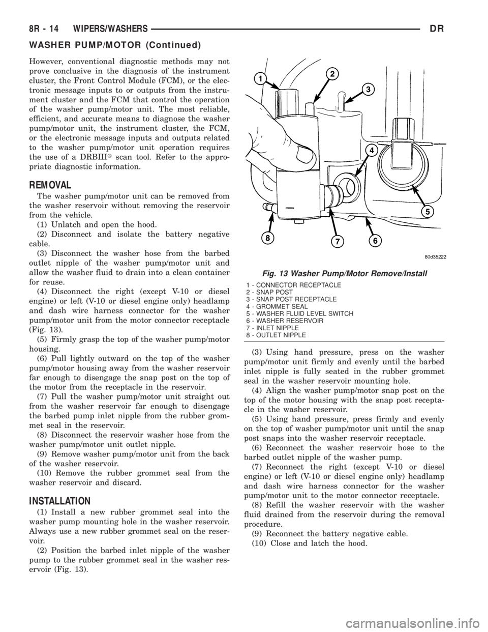
(Fig. 13).
(5) Firmly grasp the top of the washer pump/motor
housing.
(6) Pull lightly outward on the top of the washer
pump/motor housing away from the washer reservoir
far enough to disengage the snap post on the top of
the motor from the receptacle in the reservoir.
(7) Pull the washer pump/motor unit straight out
from the washer reservoir far enough to disengage
the barbed pump inlet nipple from the rubber grom-
met seal in the reservoir.
(8) Disconnect the reservoir washer hose from the
washer pump/motor unit outlet nipple.
(9) Remove washer pump/motor unit from the back
of the washer reservoir.
(10) Remove the rubber grommet seal from the
washer reservoir and discard.
INSTALLATION
(1) Install a new rubber grommet seal into the
washer pump mounting hole in the washer reservoir.
Always use a new rubber grommet seal on the reser-
voir.
(2) Position the barbed inlet nipple of the washer
pump to the rubber grommet seal in the washer res-
ervoir (Fig. 13).(3) Using hand pressure, press on the washer
pump/motor unit firmly and evenly until the barbed
inlet nipple is fully seated in the rubber grommet
seal in the washer reservoir mounting hole.
(4) Align the washer pump/motor snap post on the
top of the motor housing with the snap post recepta-
cle in the washer reservoir.
(5) Using hand pressure, press firmly and evenly
on the top of washer pump/motor unit until the snap
post snaps into the washer reservoir receptacle.
(6) Reconnect the washer reservoir hose to the
barbed outlet nipple of the washer pump.
(7) Reconnect the right (except V-10 or diesel
engine) or left (V-10 or diesel engine only) headlamp
and dash wire harness connector for the washer
pump/motor unit to the motor connector receptacle.
(8) Refill the washer reservoir with the washer
fluid drained from the reservoir during the removal
procedure.
(9) Reconnect the battery negative cable.
(10) Close and latch the hood.
Fig. 13 Washer Pump/Motor Remove/Install
1 - CONNECTOR RECEPTACLE
2 - SNAP POST
3 - SNAP POST RECEPTACLE
4 - GROMMET SEAL
5 - WASHER FLUID LEVEL SWITCH
6 - WASHER RESERVOIR
7 - INLET NIPPLE
8 - OUTLET NIPPLE
8R - 14 WIPERS/WASHERSDR
WASHER PUMP/MOTOR (Continued)
Page 696 of 2895
The wiper high/low relay terminals are connected
to the vehicle electrical system through a connector
receptacle in the Integrated Power Module (IPM).
The inputs and outputs of the wiper high/low relay
include:
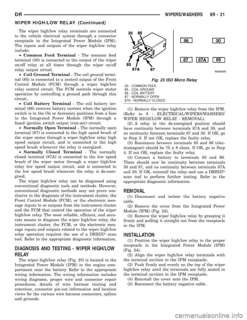
²Common Feed Terminal- The common feed
terminal (30) is connected to the output of the wiper
on/off relay at all times through the wiper on/off
relay output circuit.
²Coil Ground Terminal- The coil ground termi-
nal (85) is connected to a control output of the Front
Control Module (FCM) through a wiper high/low
relay control circuit. The FCM controls wiper motor
operation by controlling a ground path through this
circuit.
²Coil Battery Terminal- The coil battery ter-
minal (86) receives battery current when the ignition
switch is in the On or Accessory positions from a fuse
in the Integrated Power Module (IPM) through a
fused ignition switch output (run-acc) circuit.
²Normally Open Terminal- The normally open
terminal (87) is connected to the high speed brush of
the wiper motor through a wiper high/low relay high
speed output circuit, and is connected to the high
speed brush whenever the relay is energized.
²Normally Closed Terminal- The normally
closed terminal (87A) is connected to the low speed
brush of the wiper motor through a wiper high/low
relay low speed output circuit, and is connected to
the low speed brush whenever the relay is de-ener-
gized.
The wiper high/low relay can be diagnosed using
conventional diagnostic tools and methods. However,
conventional diagnostic methods may not prove con-
clusive in the diagnosis of the instrument cluster, the
Front Control Module (FCM), or the electronic mes-
sage inputs to or outputs from the instrument cluster
and the FCM that control the operation of the wiper
high/low relay. The most reliable, efficient, and accu-
rate means to diagnose the wiper high/low relay, the
instrument cluster, the FCM, or the electronic mes-
sage inputs and outputs related to the wiper high/low
relay operation requires the use of a DRBIIItscan
tool. Refer to the appropriate diagnostic information.
DIAGNOSIS AND TESTING - WIPER HIGH/LOW
RELAY
The wiper high/low relay (Fig. 23) is located in the
Integrated Power Module (IPM) in the engine com-
partment near the battery. Refer to the appropriate
wiring information. The wiring information includes
wiring diagrams, proper wire and connector repair
procedures, details of wire harness routing and
retention, connector pin-out information and location
views for the various wire harness connectors, splices
and grounds.(1) Remove the wiper high/low relay from the IPM.
(Refer to 8 - ELECTRICAL/WIPERS/WASHERS/
WIPER HIGH/LOW RELAY - REMOVAL).
(2) A relay in the de-energized position should
have continuity between terminals 87A and 30, and
no continuity between terminals 87 and 30. If OK, go
to Step 3. If not OK, replace the faulty relay.
(3) Resistance between terminals 85 and 86 (elec-
tromagnet) should be 75 8 ohms. If OK, go to Step
4. If not OK, replace the faulty relay.
(4) Connect a battery to terminals 85 and 86.
There should now be continuity between terminals
30 and 87, and no continuity between terminals 87A
and 30. If OK, reinstall the relay and use a DRBIIIt
scan tool to perform further testing. Refer to the
appropriate diagnostic information.
REMOVAL
(1) Disconnect and isolate the battery negative
cable.
(2) Remove the cover from the Integrated Power
Module (IPM) (Fig. 24).
(3) Remove the wiper high/low relay by grasping it
firmly and pulling it straight out from the receptacle
in the IPM.
INSTALLATION
(1) Position the wiper high/low relay to the proper
receptacle in the Integrated Power Module (IPM)
(Fig. 24).
(2) Align the wiper high/low relay terminals with
the terminal cavities in the IPM receptacle.
(3) Push firmly and evenly on the top of the wiper
high/low relay until the terminals are fully seated in
the terminal cavities in the IPM receptacle.
(4) Reinstall the cover onto the IPM.
(5) Reconnect the battery negative cable.
Fig. 23 ISO Micro Relay
30 - COMMON FEED
85 - COIL GROUND
86 - COIL BATTERY
87 - NORMALLY OPEN
87A - NORMALLY CLOSED
DRWIPERS/WASHERS 8R - 21
WIPER HIGH/LOW RELAY (Continued)
Page 700 of 2895
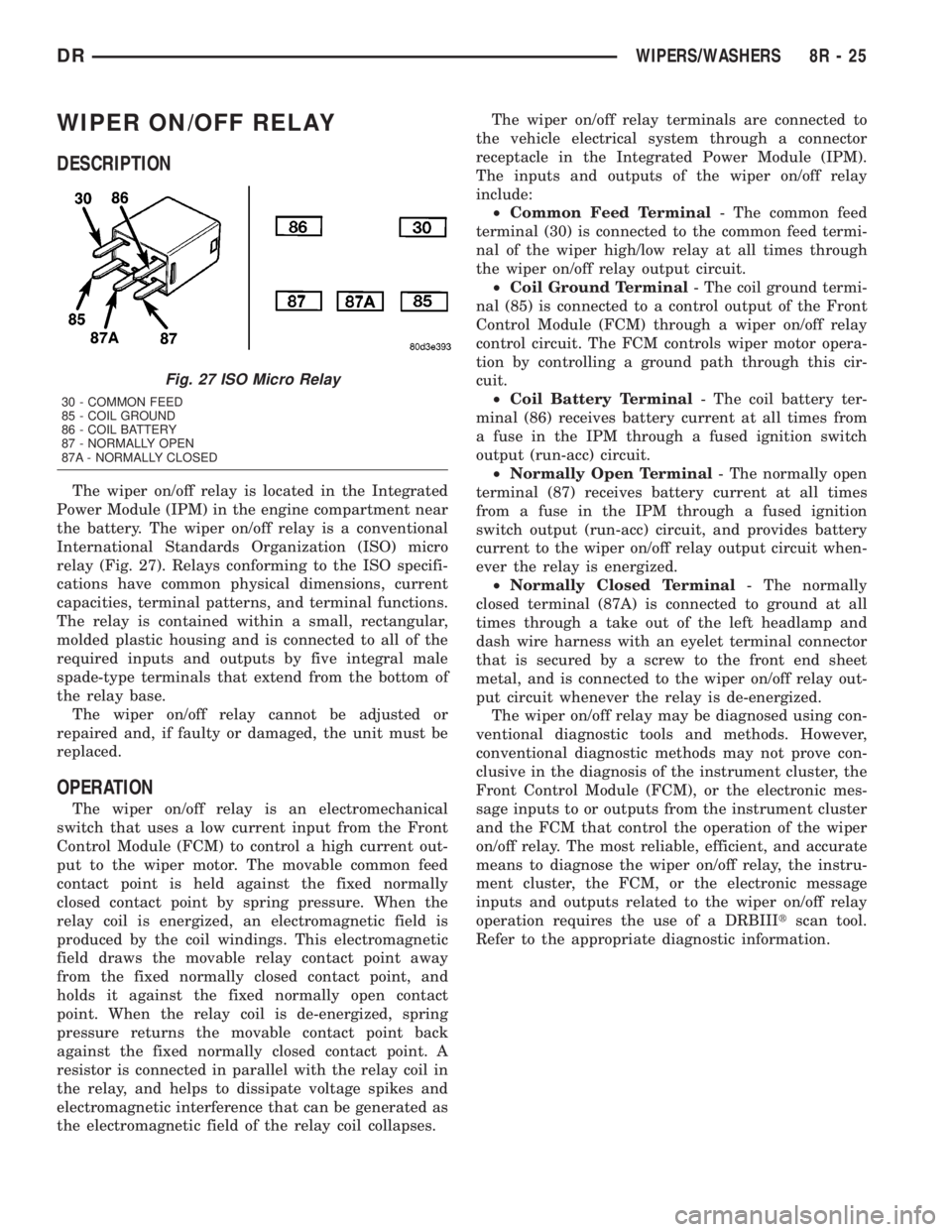
WIPER ON/OFF RELAY
DESCRIPTION
The wiper on/off relay is located in the Integrated
Power Module (IPM) in the engine compartment near
the battery. The wiper on/off relay is a conventional
International Standards Organization (ISO) micro
relay (Fig. 27). Relays conforming to the ISO specifi-
cations have common physical dimensions, current
capacities, terminal patterns, and terminal functions.
The relay is contained within a small, rectangular,
molded plastic housing and is connected to all of the
required inputs and outputs by five integral male
spade-type terminals that extend from the bottom of
the relay base.
The wiper on/off relay cannot be adjusted or
repaired and, if faulty or damaged, the unit must be
replaced.
OPERATION
The wiper on/off relay is an electromechanical
switch that uses a low current input from the Front
Control Module (FCM) to control a high current out-
put to the wiper motor. The movable common feed
contact point is held against the fixed normally
closed contact point by spring pressure. When the
relay coil is energized, an electromagnetic field is
produced by the coil windings. This electromagnetic
field draws the movable relay contact point away
from the fixed normally closed contact point, and
holds it against the fixed normally open contact
point. When the relay coil is de-energized, spring
pressure returns the movable contact point back
against the fixed normally closed contact point. A
resistor is connected in parallel with the relay coil in
the relay, and helps to dissipate voltage spikes and
electromagnetic interference that can be generated as
the electromagnetic field of the relay coil collapses.The wiper on/off relay terminals are connected to
the vehicle electrical system through a connector
receptacle in the Integrated Power Module (IPM).
The inputs and outputs of the wiper on/off relay
include:
²Common Feed Terminal- The common feed
terminal (30) is connected to the common feed termi-
nal of the wiper high/low relay at all times through
the wiper on/off relay output circuit.
²Coil Ground Terminal- The coil ground termi-
nal (85) is connected to a control output of the Front
Control Module (FCM) through a wiper on/off relay
control circuit. The FCM controls wiper motor opera-
tion by controlling a ground path through this cir-
cuit.
²Coil Battery Terminal- The coil battery ter-
minal (86) receives battery current at all times from
a fuse in the IPM through a fused ignition switch
output (run-acc) circuit.
²Normally Open Terminal- The normally open
terminal (87) receives battery current at all times
from a fuse in the IPM through a fused ignition
switch output (run-acc) circuit, and provides battery
current to the wiper on/off relay output circuit when-
ever the relay is energized.
²Normally Closed Terminal- The normally
closed terminal (87A) is connected to ground at all
times through a take out of the left headlamp and
dash wire harness with an eyelet terminal connector
that is secured by a screw to the front end sheet
metal, and is connected to the wiper on/off relay out-
put circuit whenever the relay is de-energized.
The wiper on/off relay may be diagnosed using con-
ventional diagnostic tools and methods. However,
conventional diagnostic methods may not prove con-
clusive in the diagnosis of the instrument cluster, the
Front Control Module (FCM), or the electronic mes-
sage inputs to or outputs from the instrument cluster
and the FCM that control the operation of the wiper
on/off relay. The most reliable, efficient, and accurate
means to diagnose the wiper on/off relay, the instru-
ment cluster, the FCM, or the electronic message
inputs and outputs related to the wiper on/off relay
operation requires the use of a DRBIIItscan tool.
Refer to the appropriate diagnostic information.
Fig. 27 ISO Micro Relay
30 - COMMON FEED
85 - COIL GROUND
86 - COIL BATTERY
87 - NORMALLY OPEN
87A - NORMALLY CLOSED
DRWIPERS/WASHERS 8R - 25
Page 702 of 2895
WIRING
TABLE OF CONTENTS
page page
WIRING DIAGRAM INFORMATION....... 8W-01-1
COMPONENT INDEX.................. 8W-02-1
POWER DISTRIBUTION............... 8W-10-1
GROUND DISTRIBUTION.............. 8W-15-1
BUS COMMUNICATIONS.............. 8W-18-1
CHARGING SYSTEM.................. 8W-20-1
STARTING SYSTEM.................. 8W-21-1
FUEL/IGNITION SYSTEM.............. 8W-30-1
TRANSMISSION CONTROL SYSTEM..... 8W-31-1
VEHICLE SPEED CONTROL............ 8W-33-1
REAR WHEEL ANTILOCK BRAKES....... 8W-34-1
ALL WHEEL ANTILOCK BRAKES........ 8W-35-1
VEHICLE THEFT SECURITY SYSTEM..... 8W-39-1
INSTRUMENT CLUSTER............... 8W-40-1
HORN/CIGAR LIGHTER/POWER OUTLET . . 8W-41-1
AIR CONDITIONING.................. 8W-42-1
AIRBAG SYSTEM.................... 8W-43-1INTERIOR LIGHTING.................. 8W-44-1
AUDIO SYSTEM..................... 8W-47-1
OVERHEAD CONSOLE................. 8W-49-1
FRONT LIGHTING.................... 8W-50-1
REAR LIGHTING..................... 8W-51-1
TURN SIGNALS...................... 8W-52-1
WIPERS............................ 8W-53-1
TRAILER TOW....................... 8W-54-1
POWER WINDOWS................... 8W-60-1
POWER DOOR LOCKS................ 8W-61-1
POWER MIRRORS................... 8W-62-1
POWER SEATS...................... 8W-63-1
SPLICE INFORMATION................ 8W-70-1
CONNECTOR PIN-OUTS............... 8W-80-1
CONNECTOR/GROUND/SPLICE
LOCATION........................ 8W-91-1
POWER DISTRIBUTION............... 8W-97-1 DRWIRING 8W - 1
Page 720 of 2895

8W-02 COMPONENT INDEX
Component Page
4WD Switch......................... 8W-30
A/C Compressor Clutch Relay............ 8W-42
A/C Compressor Clutch................. 8W-42
A/C Pressure Transducer................ 8W-42
A/C-Heater Control.................... 8W-42
Accelerator Pedal Position Sensor......... 8W-30
Adjustable Pedal Motor................. 8W-30
Adjustable Pedal Relay................. 8W-30
Adjustable Pedal Switch................ 8W-30
Airbag Control Modules................ 8W-43
Airbags............................. 8W-43
Ambient Temperature Sensor............ 8W-49
Amplifier Audio....................... 8W-47
Auto Shut Down Relay................. 8W-30
Automatic Day/Night Mirror............. 8W-49
Auxiliary Battery..................... 8W-20
Backup Lamp Switch.................. 8W-51
Battery Temperature Sensor............. 8W-30
Battery............................. 8W-20
Blend Door Actuator................... 8W-42
Blower Motor Resistor Block............. 8W-42
Blower Motor......................... 8W-42
Brake Lamp Switch.................... 8W-33
Brake Transmission Shift Interlock
Solenoid........................... 8W-40
Camshaft Position Sensor............... 8W-30
Capacitor............................ 8W-30
Center High Mounted Stop Lamp/Cargo
Lamp.......................... 8W-44, 51
Center High Mounted Stop Lamp-
Aftermarket..................... 8W-33, 51
Cigar Lighter Outlet................... 8W-41
Circuit Breaker....................... 8W-10
Clearance Lamps...................... 8W-50
Clockspring................. 8W-33, 41, 43, 47
Clutch Interlock Brake Switch........... 8W-21
Coil On Plugs........................ 8W-30
Compass/Mini-Trip Computer............ 8W-49
Condenser Fan Relay.................. 8W-42
Condenser Fan....................... 8W-42
Controller Antilock Brake............ 8W-34, 35
Crankshaft Position Sensor.............. 8W-30
Cylinder Lock Switch-Driver............. 8W-61
Cylinder Lock Switch-Passenger.......... 8W-61
Data Link Connector................... 8W-18
Data Link Connector-Engine............. 8W-18
Dome Lamp.......................... 8W-44
Door Ajar Switches.................... 8W-40
Door Lock Motor/Ajar Switches........ 8W-40, 61
Door Lock Switch-Passenger............. 8W-61
Driver Door Module.............. 8W-60, 61, 62
Electric Brake Provision............. 8W-33, 54Component Page
Electronic Throttle Control Module........ 8W-30
Engine Control Module................. 8W-30
Engine Coolant Temperature Sensor....... 8W-30
Engine Oil Pressure Switch.............. 8W-30
EVAP/Purge Solenoid.................. 8W-30
Evaporator Temperature Sensor.......... 8W-42
Fender Lamps........................ 8W-51
Fog Lamp Relay...................... 8W-50
Fog Lamps.......................... 8W-50
Front Control Module.................. 8W-10
Fuel Heater Relay..................... 8W-30
Fuel Heater.......................... 8W-30
Fuel Injectors........................ 8W-30
Fuel Injector Packs.................... 8W-30
Fuel Pump Module.................... 8W-30
Fuel Pump Motor..................... 8W-30
Fuel Pump Relay...................... 8W-30
Fuel Rail Pressure Sensor............... 8W-30
Fuses............................... 8W-10
Fusible Link......................... 8W-10
Grounds............................ 8W-15
Generator........................... 8W-20
Glove Box Lamp And Switch............. 8W-44
Headlamp Switch.................. 8W-40, 50
Headlamps.......................... 8W-50
Heated Mirror Relay................... 8W-62
Heated Seat Cushions.................. 8W-63
Heated Seat Switches.................. 8W-63
Horn Relay.......................... 8W-41
Horn Switch......................... 8W-41
Horns.............................. 8W-41
Idle Air Control Motor............ 8W-30, 30-36
Ignition Coils......................... 8W-30
Ignition Switch....................... 8W-10
Inlet Air Temperature/Pressure Sensor..... 8W-30
Input Speed Sensor.................... 8W-31
Instrument Cluster.................... 8W-40
Intake Air Heater Relays............... 8W-30
Intake Air Temperature Sensor........... 8W-30
Intake Air Temperature/Manifold Absolute
Pressure Sensor..................... 8W-30
Integrated Power Module............... 8W-10
Knock Sensors........................ 8W-30
Leak Detection Pump.................. 8W-30
License Lamps....................... 8W-51
Lift Pump Motor...................... 8W-30
Line Pressure Sensor................ 8W-30, 31
Lumbar Motors....................... 8W-63
Manifold Absolute Pressure Sensor........ 8W-30
Mode Door Actuators................... 8W-42
Multi-Function Switch............ 8W-40, 52, 53
Output Speed Sensor................... 8W-31
DR8W-02 COMPONENT INDEX 8W - 02 - 1