2003 DODGE RAM Speed sensor
[x] Cancel search: Speed sensorPage 1779 of 2895
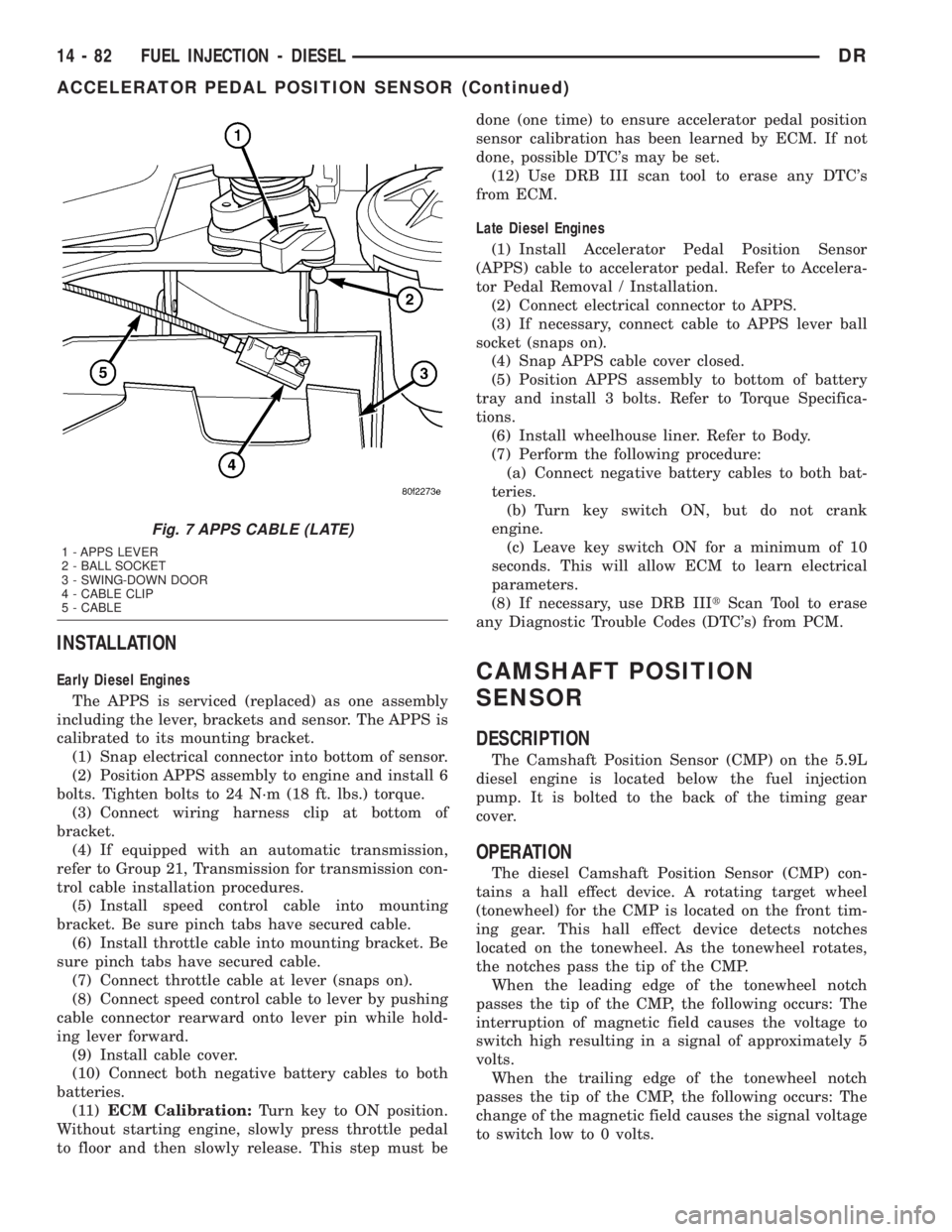
INSTALLATION
Early Diesel Engines
The APPS is serviced (replaced) as one assembly
including the lever, brackets and sensor. The APPS is
calibrated to its mounting bracket.
(1) Snap electrical connector into bottom of sensor.
(2) Position APPS assembly to engine and install 6
bolts. Tighten bolts to 24 N´m (18 ft. lbs.) torque.
(3) Connect wiring harness clip at bottom of
bracket.
(4) If equipped with an automatic transmission,
refer to Group 21, Transmission for transmission con-
trol cable installation procedures.
(5) Install speed control cable into mounting
bracket. Be sure pinch tabs have secured cable.
(6) Install throttle cable into mounting bracket. Be
sure pinch tabs have secured cable.
(7) Connect throttle cable at lever (snaps on).
(8) Connect speed control cable to lever by pushing
cable connector rearward onto lever pin while hold-
ing lever forward.
(9) Install cable cover.
(10) Connect both negative battery cables to both
batteries.
(11)ECM Calibration:Turn key to ON position.
Without starting engine, slowly press throttle pedal
to floor and then slowly release. This step must bedone (one time) to ensure accelerator pedal position
sensor calibration has been learned by ECM. If not
done, possible DTC's may be set.
(12) Use DRB III scan tool to erase any DTC's
from ECM.
Late Diesel Engines
(1) Install Accelerator Pedal Position Sensor
(APPS) cable to accelerator pedal. Refer to Accelera-
tor Pedal Removal / Installation.
(2) Connect electrical connector to APPS.
(3) If necessary, connect cable to APPS lever ball
socket (snaps on).
(4) Snap APPS cable cover closed.
(5) Position APPS assembly to bottom of battery
tray and install 3 bolts. Refer to Torque Specifica-
tions.
(6) Install wheelhouse liner. Refer to Body.
(7) Perform the following procedure:
(a) Connect negative battery cables to both bat-
teries.
(b) Turn key switch ON, but do not crank
engine.
(c) Leave key switch ON for a minimum of 10
seconds. This will allow ECM to learn electrical
parameters.
(8) If necessary, use DRB IIItScan Tool to erase
any Diagnostic Trouble Codes (DTC's) from PCM.CAMSHAFT POSITION
SENSOR
DESCRIPTION
The Camshaft Position Sensor (CMP) on the 5.9L
diesel engine is located below the fuel injection
pump. It is bolted to the back of the timing gear
cover.
OPERATION
The diesel Camshaft Position Sensor (CMP) con-
tains a hall effect device. A rotating target wheel
(tonewheel) for the CMP is located on the front tim-
ing gear. This hall effect device detects notches
located on the tonewheel. As the tonewheel rotates,
the notches pass the tip of the CMP.
When the leading edge of the tonewheel notch
passes the tip of the CMP, the following occurs: The
interruption of magnetic field causes the voltage to
switch high resulting in a signal of approximately 5
volts.
When the trailing edge of the tonewheel notch
passes the tip of the CMP, the following occurs: The
change of the magnetic field causes the signal voltage
to switch low to 0 volts.
Fig. 7 APPS CABLE (LATE)
1 - APPS LEVER
2 - BALL SOCKET
3 - SWING-DOWN DOOR
4 - CABLE CLIP
5 - CABLE
14 - 82 FUEL INJECTION - DIESELDR
ACCELERATOR PEDAL POSITION SENSOR (Continued)
Page 1780 of 2895
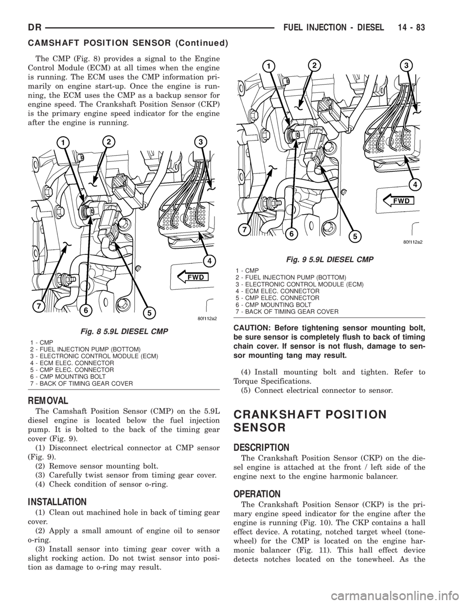
The CMP (Fig. 8) provides a signal to the Engine
Control Module (ECM) at all times when the engine
is running. The ECM uses the CMP information pri-
marily on engine start-up. Once the engine is run-
ning, the ECM uses the CMP as a backup sensor for
engine speed. The Crankshaft Position Sensor (CKP)
is the primary engine speed indicator for the engine
after the engine is running.
REMOVAL
The Camshaft Position Sensor (CMP) on the 5.9L
diesel engine is located below the fuel injection
pump. It is bolted to the back of the timing gear
cover (Fig. 9).
(1) Disconnect electrical connector at CMP sensor
(Fig. 9).
(2) Remove sensor mounting bolt.
(3) Carefully twist sensor from timing gear cover.
(4) Check condition of sensor o-ring.
INSTALLATION
(1) Clean out machined hole in back of timing gear
cover.
(2) Apply a small amount of engine oil to sensor
o-ring.
(3) Install sensor into timing gear cover with a
slight rocking action. Do not twist sensor into posi-
tion as damage to o-ring may result.CAUTION: Before tightening sensor mounting bolt,
be sure sensor is completely flush to back of timing
chain cover. If sensor is not flush, damage to sen-
sor mounting tang may result.
(4) Install mounting bolt and tighten. Refer to
Torque Specifications.
(5) Connect electrical connector to sensor.
CRANKSHAFT POSITION
SENSOR
DESCRIPTION
The Crankshaft Position Sensor (CKP) on the die-
sel engine is attached at the front / left side of the
engine next to the engine harmonic balancer.
OPERATION
The Crankshaft Position Sensor (CKP) is the pri-
mary engine speed indicator for the engine after the
engine is running (Fig. 10). The CKP contains a hall
effect device. A rotating, notched target wheel (tone-
wheel) for the CMP is located on the engine har-
monic balancer (Fig. 11). This hall effect device
detects notches located on the tonewheel. As the
Fig. 8 5.9L DIESEL CMP
1 - CMP
2 - FUEL INJECTION PUMP (BOTTOM)
3 - ELECTRONIC CONTROL MODULE (ECM)
4 - ECM ELEC. CONNECTOR
5 - CMP ELEC. CONNECTOR
6 - CMP MOUNTING BOLT
7 - BACK OF TIMING GEAR COVER
Fig. 9 5.9L DIESEL CMP
1 - CMP
2 - FUEL INJECTION PUMP (BOTTOM)
3 - ELECTRONIC CONTROL MODULE (ECM)
4 - ECM ELEC. CONNECTOR
5 - CMP ELEC. CONNECTOR
6 - CMP MOUNTING BOLT
7 - BACK OF TIMING GEAR COVER
DRFUEL INJECTION - DIESEL 14 - 83
CAMSHAFT POSITION SENSOR (Continued)
Page 1781 of 2895
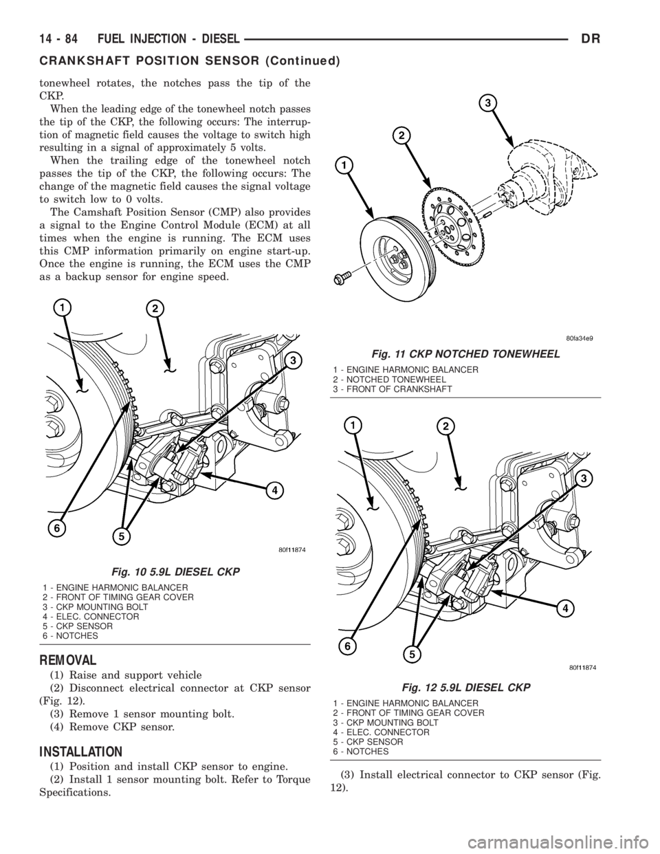
tonewheel rotates, the notches pass the tip of the
CKP.
When the leading edge of the tonewheel notch passes
the tip of the CKP, the following occurs: The interrup-
tion of magnetic field causes the voltage to switch high
resulting in a signal of approximately 5 volts.
When the trailing edge of the tonewheel notch
passes the tip of the CKP, the following occurs: The
change of the magnetic field causes the signal voltage
to switch low to 0 volts.
The Camshaft Position Sensor (CMP) also provides
a signal to the Engine Control Module (ECM) at all
times when the engine is running. The ECM uses
this CMP information primarily on engine start-up.
Once the engine is running, the ECM uses the CMP
as a backup sensor for engine speed.
REMOVAL
(1) Raise and support vehicle
(2) Disconnect electrical connector at CKP sensor
(Fig. 12).
(3) Remove 1 sensor mounting bolt.
(4) Remove CKP sensor.
INSTALLATION
(1) Position and install CKP sensor to engine.
(2) Install 1 sensor mounting bolt. Refer to Torque
Specifications.(3) Install electrical connector to CKP sensor (Fig.
12).
Fig. 10 5.9L DIESEL CKP
1 - ENGINE HARMONIC BALANCER
2 - FRONT OF TIMING GEAR COVER
3 - CKP MOUNTING BOLT
4 - ELEC. CONNECTOR
5 - CKP SENSOR
6 - NOTCHES
Fig. 11 CKP NOTCHED TONEWHEEL
1 - ENGINE HARMONIC BALANCER
2 - NOTCHED TONEWHEEL
3 - FRONT OF CRANKSHAFT
Fig. 12 5.9L DIESEL CKP
1 - ENGINE HARMONIC BALANCER
2 - FRONT OF TIMING GEAR COVER
3 - CKP MOUNTING BOLT
4 - ELEC. CONNECTOR
5 - CKP SENSOR
6 - NOTCHES
14 - 84 FUEL INJECTION - DIESELDR
CRANKSHAFT POSITION SENSOR (Continued)
Page 1792 of 2895
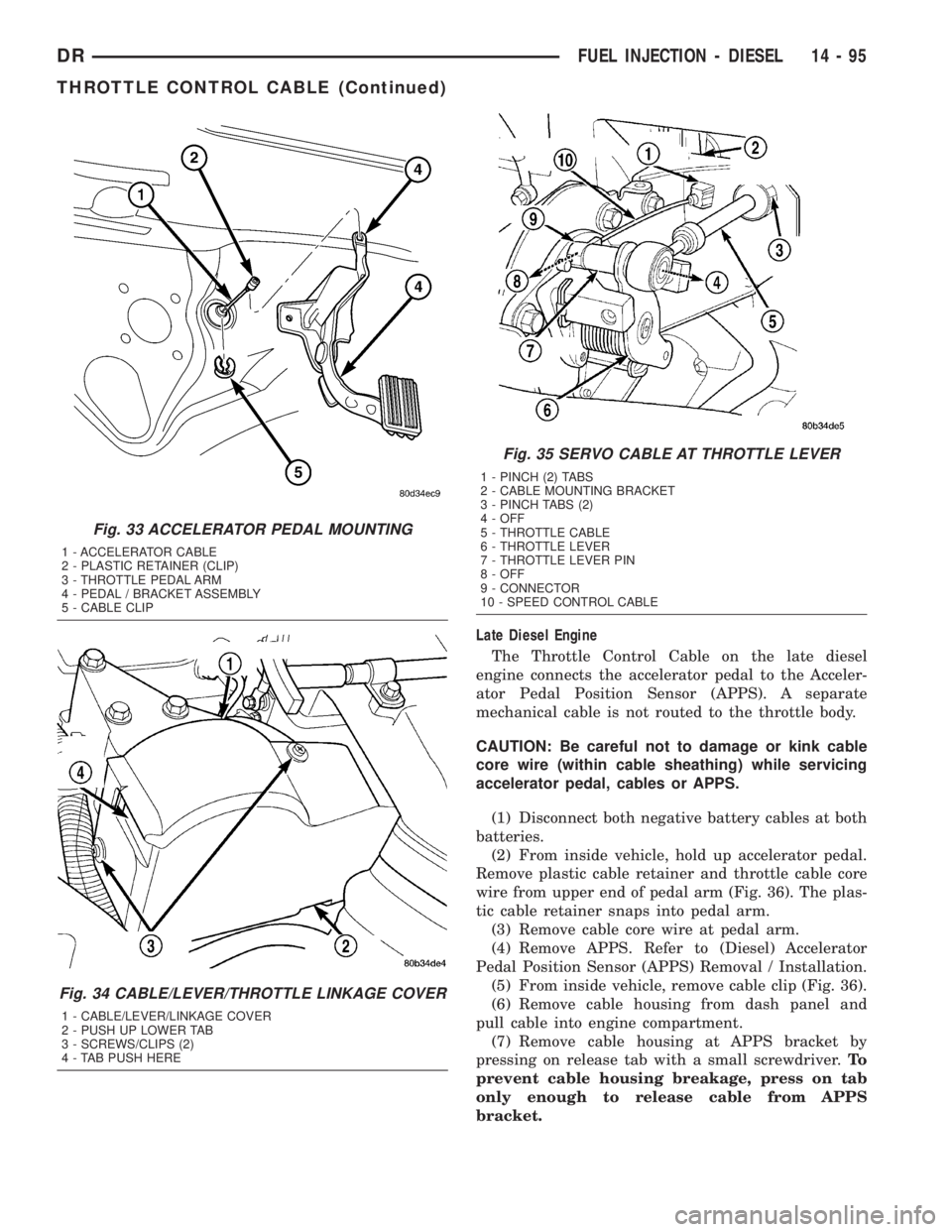
Late Diesel Engine
The Throttle Control Cable on the late diesel
engine connects the accelerator pedal to the Acceler-
ator Pedal Position Sensor (APPS). A separate
mechanical cable is not routed to the throttle body.
CAUTION: Be careful not to damage or kink cable
core wire (within cable sheathing) while servicing
accelerator pedal, cables or APPS.
(1) Disconnect both negative battery cables at both
batteries.
(2) From inside vehicle, hold up accelerator pedal.
Remove plastic cable retainer and throttle cable core
wire from upper end of pedal arm (Fig. 36). The plas-
tic cable retainer snaps into pedal arm.
(3) Remove cable core wire at pedal arm.
(4) Remove APPS. Refer to (Diesel) Accelerator
Pedal Position Sensor (APPS) Removal / Installation.
(5) From inside vehicle, remove cable clip (Fig. 36).
(6) Remove cable housing from dash panel and
pull cable into engine compartment.
(7) Remove cable housing at APPS bracket by
pressing on release tab with a small screwdriver.To
prevent cable housing breakage, press on tab
only enough to release cable from APPS
bracket.
Fig. 33 ACCELERATOR PEDAL MOUNTING
1 - ACCELERATOR CABLE
2 - PLASTIC RETAINER (CLIP)
3 - THROTTLE PEDAL ARM
4 - PEDAL / BRACKET ASSEMBLY
5 - CABLE CLIP
Fig. 34 CABLE/LEVER/THROTTLE LINKAGE COVER
1 - CABLE/LEVER/LINKAGE COVER
2 - PUSH UP LOWER TAB
3 - SCREWS/CLIPS (2)
4 - TAB PUSH HERE
Fig. 35 SERVO CABLE AT THROTTLE LEVER
1 - PINCH (2) TABS
2 - CABLE MOUNTING BRACKET
3 - PINCH TABS (2)
4 - OFF
5 - THROTTLE CABLE
6 - THROTTLE LEVER
7 - THROTTLE LEVER PIN
8 - OFF
9 - CONNECTOR
10 - SPEED CONTROL CABLE
DRFUEL INJECTION - DIESEL 14 - 95
THROTTLE CONTROL CABLE (Continued)
Page 1883 of 2895
(5) Remove shift tower and isolator plate from
transmission shift cover.
(6) Raise and support vehicle.
(7) Remove skid plate, if equipped.
(8) Mark propeller shaft and axle yokes for instal-
lation reference and remove shaft/shafts.
(9) Remove exhaust system Y-pipe.
(10) Disconnect speed sensor and backup light
switch connectors.
(11) Support engine with safety stand and a wood
block.
(12) If transmission is to be disassembled, remove
drain bolt at bottom of PTO cover and drain lubri-
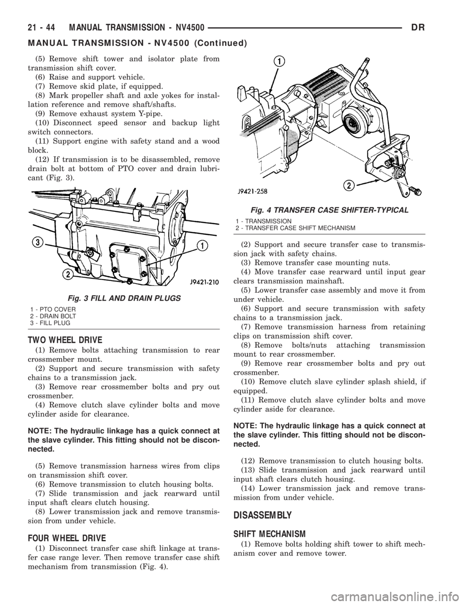
cant (Fig. 3).
TWO WHEEL DRIVE
(1) Remove bolts attaching transmission to rear
crossmember mount.
(2) Support and secure transmission with safety
chains to a transmission jack.
(3) Remove rear crossmember bolts and pry out
crossmenber.
(4) Remove clutch slave cylinder bolts and move
cylinder aside for clearance.
NOTE: The hydraulic linkage has a quick connect at
the slave cylinder. This fitting should not be discon-
nected.
(5) Remove transmission harness wires from clips
on transmission shift cover.
(6) Remove transmission to clutch housing bolts.
(7) Slide transmission and jack rearward until
input shaft clears clutch housing.
(8) Lower transmission jack and remove transmis-
sion from under vehicle.
FOUR WHEEL DRIVE
(1) Disconnect transfer case shift linkage at trans-
fer case range lever. Then remove transfer case shift
mechanism from transmission (Fig. 4).(2) Support and secure transfer case to transmis-
sion jack with safety chains.
(3) Remove transfer case mounting nuts.
(4) Move transfer case rearward until input gear
clears transmission mainshaft.
(5) Lower transfer case assembly and move it from
under vehicle.
(6) Support and secure transmission with safety
chains to a transmission jack.
(7) Remove transmission harness from retaining
clips on transmission shift cover.
(8) Remove bolts/nuts attaching transmission
mount to rear crossmember.
(9) Remove rear crossmember bolts and pry out
crossmenber.
(10) Remove clutch slave cylinder splash shield, if
equipped.
(11) Remove clutch slave cylinder bolts and move
cylinder aside for clearance.
NOTE: The hydraulic linkage has a quick connect at
the slave cylinder. This fitting should not be discon-
nected.
(12) Remove transmission to clutch housing bolts.
(13) Slide transmission and jack rearward until
input shaft clears clutch housing.
(14) Lower transmission jack and remove trans-
mission from under vehicle.
DISASSEMBLY
SHIFT MECHANISM
(1) Remove bolts holding shift tower to shift mech-
anism cover and remove tower.
Fig. 3 FILL AND DRAIN PLUGS
1 - PTO COVER
2 - DRAIN BOLT
3 - FILL PLUG
Fig. 4 TRANSFER CASE SHIFTER-TYPICAL
1 - TRANSMISSION
2 - TRANSFER CASE SHIFT MECHANISM
21 - 44 MANUAL TRANSMISSION - NV4500DR
MANUAL TRANSMISSION - NV4500 (Continued)
Page 1917 of 2895
²release fork ball stud.
²propeller shaft slip yoke.
(2) Apply sealer to threads of bottom PTO cover
bolt and install bolt in case.
(3) Mount transmission on jack and position trans-
mission under vehicle.
(4) Raise transmission until input shaft is centered
in release bearing and clutch disc hub.
(5) Move transmission forward and start input
shaft in release bearing, clutch disc and pilot bush-
ing.
(6) Work transmission forward until seated against
clutch housing. Do not allow transmission to remain
unsupported after input shaft has entered clutch
disc.
(7) Install transmission bolts and tighten to 108
N´m (80 ft. lbs.).
(8) Install transmission mount on transmission or
rear crossmember.
(9) Install rear crossmember.
(10) Remove transmission jack and engine support
fixture.
(11) Position transmission harness wires in clips
on shift cover.
(12) Install clutch slave cylinder and install slave
cylinder shield, if equipped.
(13) Connect speed sensor and backup light switch
wires.
TWO WHEEL DRIVE
(1) Fill transmission with recommended lubricant.
Correct fill level is bottom edge of fill plug hole.
(2) Align and install propeller shaft.
(3) Lower vehicle.
(4) Clean the mating surfaces of shift tower, isola-
tor plate and shift cover with suitable wax and
grease remover.
(5) Apply Mopar Gasket Maker or equivalent to
the sealing surface of the shift cover. Do not over
apply sealant.
(6) Install the isolator plate onto the shift cover,
metal side down.
(7) Install the shift tower onto the isolator plate.
No sealant is necessary between the shift tower and
the isolator plate.
(8) Verify that the shift tower, isolator plate and
the shift tower bushings are properly aligned.
(9) Install the bolts to hold the shift tower to the
isolator plate and the shift cover. Tighten the shift
tower bolts to 10.2-11.25 N´m (7.5-8.3 ft. lbs.).
(10) Install the shift lever extension onto the shift
tower and lever assembly.
(11) Install shift boot and bezel.
(12) Connect battery negative cable.
FOUR WHEEL DRIVE
(1) Install transfer case shift mechanism on trans-
mission.
(2) Install transfer case on transmission jack.
Secure transfer case to jack with safety chains.
(3) Raise jack and align transfer case input gear
with transmission mainshaft.
(4) Move transfer case forward and seat it on
adapter.
(5) Install transfer case nuts and tighten to:
²If 3/8 studs 41-47 N´m (30-35 ft. lbs.).
²If 5/16 studs 30-41 N´m (22-30 ft. lbs.).
(6) Install transfer case shift mechanism to side of
transfer case.
(7) Connect transfer case shift lever to range lever
on transfer case.
(8) Align and connect propeller shafts.
(9) Fill transmission with required lubricant.
Check lubricant level in transfer case and add lubri-
cant if necessary.
(10) Install transfer case skid plate, if equipped
and crossmember. Tighten attaching bolts/nuts to 41
N´m (30 ft. lbs.).
(11) Install exhaust system components.
(12) Lower vehicle.
(13) Clean the mating surfaces of shift tower, iso-
lator plate and shift cover with suitable wax and
grease remover.
(14) Apply Mopar Gasket Maker or equivalent to
the sealing surface of the shift cover. Do not over
apply sealant.
(15) Install the isolator plate onto the shift cover,
metal side down.
(16) Install the shift tower onto the isolator plate.
No sealant is necessary between the shift tower and
the isolator plate.
(17) Verify that the shift tower, isolator plate and
the shift tower bushings are properly aligned.
(18) Install the bolts to hold the shift tower to the
isolator plate and the shift cover. Tighten the shift
tower bolts to 10.2-11.25 N´m (7.5-8.3 ft. lbs.).
(19) Install the shift lever extension onto the shift
tower and lever assembly.
(20) Install shift lever boot and bezel.
(21) Connect battery negative cable.
21 - 78 MANUAL TRANSMISSION - NV4500DR
MANUAL TRANSMISSION - NV4500 (Continued)
Page 1969 of 2895
CLEANING...........................214
INSPECTION.........................214
ASSEMBLY...........................215
OUTPUT SHAFT FRONT BEARING
REMOVAL............................217
INSTALLATION........................217
OUTPUT SHAFT REAR BEARING
REMOVAL............................217
INSTALLATION........................217
OVERDRIVE CLUTCH
DESCRIPTION........................218
OPERATION..........................218
OVERDRIVE SWITCH
DESCRIPTION........................218
OPERATION..........................218
DIAGNOSIS AND TESTING - OVERDRIVE
ELECTRICAL CONTROLS..............219
REMOVAL............................219
INSTALLATION........................219
OVERDRIVE UNIT
REMOVAL............................220
DISASSEMBLY........................220
CLEANING...........................227
INSPECTION.........................227
ASSEMBLY...........................228
INSTALLATION........................236
OVERRUNNING CLUTCH CAM/OVERDRIVE
PISTON RETAINER
DESCRIPTION........................237
OPERATION..........................237
DISASSEMBLY........................238
CLEANING...........................238
INSPECTION.........................238
ASSEMBLY...........................239
PISTONS
DESCRIPTION........................241
OPERATION..........................241
PLANETARY GEARTRAIN/OUTPUT SHAFT
DESCRIPTION........................242
OPERATION..........................243
DISASSEMBLY........................243
INSPECTION.........................245
ASSEMBLY...........................245
REAR CLUTCH
DESCRIPTION........................248
OPERATION..........................249
DISASSEMBLY........................249
CLEANING...........................250
INSPECTION.........................250
ASSEMBLY...........................250REAR SERVO
DESCRIPTION........................252
OPERATION..........................252
DISASSEMBLY........................252
CLEANING...........................252
ASSEMBLY...........................253
SHIFT MECHANISM
DESCRIPTION........................253
OPERATION..........................253
SOLENOID
DESCRIPTION........................253
OPERATION..........................254
SPEED SENSOR
DESCRIPTION........................254
OPERATION..........................254
THROTTLE VALVE CABLE
DESCRIPTION........................254
ADJUSTMENTS - THROTTLE VALVE
CABLE.............................255
TORQUE CONVERTER
DESCRIPTION........................257
OPERATION..........................261
REMOVAL............................262
INSTALLATION........................262
TORQUE CONVERTER DRAINBACK VALVE
DESCRIPTION........................262
OPERATION..........................262
STANDARD PROCEDURE - TORQUE
CONVERTER DRAINBACK VALVE........262
TRANSMISSION RANGE SENSOR
DESCRIPTION........................263
OPERATION..........................263
DIAGNOSIS AND TESTING - TRANSMISSION
RANGE SENSOR (TRS)................264
REMOVAL............................265
INSTALLATION........................266
TRANSMISSION TEMPERATURE SENSOR
DESCRIPTION........................267
OPERATION..........................267
VALVE BODY
DESCRIPTION........................267
OPERATION..........................272
REMOVAL............................286
DISASSEMBLY........................287
CLEANING...........................298
INSPECTION.........................298
ASSEMBLY...........................299
INSTALLATION........................307
ADJUSTMENTS - VALVE BODY...........308
21 - 130 AUTOMATIC TRANSMISSION - 46REDR
Page 1981 of 2895
Test Four - Transmission In Reverse
This test checks pump output, pressure regulation
and the front clutch and rear servo circuits. Use 300
psi Test Gauge C-3293-SP for this test.
(1) Leave vehicle on hoist and leave gauge C-3292
in place at accumulator port.
(2) Move 300 psi Gauge C-3293-SP back to rear
servo port.
(3) Have helper start and run engine at 1600 rpm
for test.
(4) Move transmission shift lever four detents
rearward from full forward position. This is Reverse
range.
(5) Move transmission throttle lever fully forward
then fully rearward and note reading at Gauge
C-3293-SP.
(6) Pressure should be 145 - 175 psi (1000-1207
kPa) with throttle lever forward and increase to 230 -
280 psi (1586-1931 kPa) as lever is gradually moved
rearward.
Test Five - Governor Pressure
This test checks governor operation by measuring
governor pressure response to changes in vehicle
speed. It is usually not necessary to check governor
operation unless shift speeds are incorrect or if the
transmission will not downshift. The test should be
performed on the road or on a hoist that will allow
the rear wheels to rotate freely.
(1) Move 100 psi Test Gauge C-3292 to governor
pressure port.
(2) Move transmission shift lever two detents rear-
ward from full forward position. This is D range.
(3) Have helper start and run engine at curb idle
speed. Then firmly apply service brakes so wheels
will not rotate.
(4) Note governor pressure:
²Governor pressure should be no more than 20.6
kPa (3 psi) at curb idle speed and wheels not rotat-
ing.
²If pressure exceeds 20.6 kPa (3 psi), a fault
exists in governor pressure control system.
(5) Release brakes, slowly increase engine speed,
and observe speedometer and pressure test gauge (do
not exceed 30 mph on speedometer). Governor pres-
sure should increase in proportion to vehicle speed.
Or approximately 6.89 kPa (1 psi) for every 1 mph.
(6) Governor pressure rise should be smooth and
drop back to no more than 20.6 kPa (3 psi), after
engine returns to curb idle and brakes are applied to
prevent wheels from rotating.
(7) Compare results of pressure test with analysis
chart.Test Six - Transmission In Overdrive Fourth Gear
This test checks line pressure at the overdrive
clutch in fourth gear range. Use 300 psi Test Gauge
C-3293-SP for this test. The test should be performed
on the road or on a chassis dyno.
(1) Remove tachometer; it is not needed for this
test.
(2) Move 300 psi Gauge to overdrive clutch pres-
sure test port. Then remove other gauge and reinstall
test port plug.
(3) Lower vehicle.
(4) Turn OD switch on.
(5) Secure test gauge so it can be viewed from
drivers seat.
(6) Start engine and shift into D range.
(7) Increase vehicle speed gradually until 3-4 shift
occurs and note gauge pressure.
(8) Pressure should be 469-496 kPa (68-72 psi)
with closed throttle and increase to 620-827 kPa (90-
120 psi) at 1/2 to 3/4 throttle. Note that pressure can
increase to around 896 kPa (130 psi) at full throttle.
(9) Return to shop or move vehicle off chassis
dyno.
PRESSURE TEST ANALYSIS CHART
TEST CONDITION INDICATION
Line pressure OK during any
one testPump and regulator valve
OK
Line pressure OK in R but
low in D, 2, 1Leakage in rear clutch area
(seal rings, clutch seals)
Pressure low in D Fourth
Gear RangeOverdrive clutch piston
seal, or check ball problem
Pressure OK in 1, 2 but low
in D3 and RLeakage in front clutch area
Pressure OK in 2 but low in
R and 1Leakage in rear servo
Front servo pressure in 2 Leakage in servo; broken
servo ring or cracked servo
piston
Pressure low in all positions Clogged filter, stuck
regulator valve, worn or
faulty pump, low oil level
Governor pressure too high
at idle speedGovernor pressure solenoid
valve system fault. Refer to
diagnostic book.
Governor pressure low at all
mph figuresFaulty governor pressure
solenoid, transmission
control module, or governor
pressure sensor
Lubrication pressure low at
all throttle positionsClogged fluid cooler or
lines, seal rings leaking,
worn pump bushings,
pump, clutch retainer, or
clogged filter.
Line pressure high Output shaft plugged, sticky
regulator valve
Line pressure low Sticky regulator valve,
clogged filter, worn pump
21 - 142 AUTOMATIC TRANSMISSION - 46REDR
AUTOMATIC TRANSMISSION - 46RE (Continued)