2003 DODGE RAM Speed sensor
[x] Cancel search: Speed sensorPage 2336 of 2895
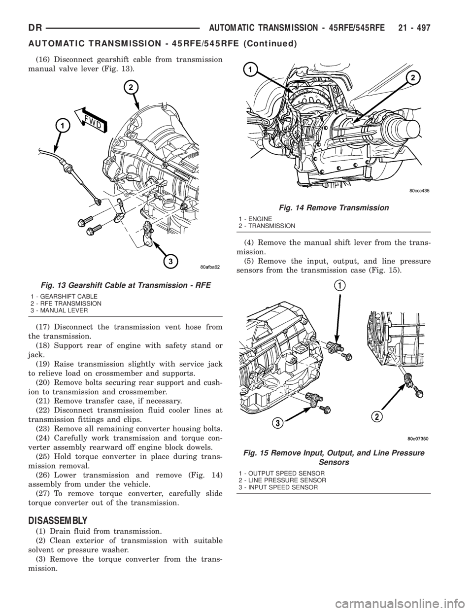
(16) Disconnect gearshift cable from transmission
manual valve lever (Fig. 13).
(17) Disconnect the transmission vent hose from
the transmission.
(18) Support rear of engine with safety stand or
jack.
(19) Raise transmission slightly with service jack
to relieve load on crossmember and supports.
(20) Remove bolts securing rear support and cush-
ion to transmission and crossmember.
(21) Remove transfer case, if necessary.
(22) Disconnect transmission fluid cooler lines at
transmission fittings and clips.
(23) Remove all remaining converter housing bolts.
(24) Carefully work transmission and torque con-
verter assembly rearward off engine block dowels.
(25) Hold torque converter in place during trans-
mission removal.
(26) Lower transmission and remove (Fig. 14)
assembly from under the vehicle.
(27) To remove torque converter, carefully slide
torque converter out of the transmission.
DISASSEMBLY
(1) Drain fluid from transmission.
(2) Clean exterior of transmission with suitable
solvent or pressure washer.
(3) Remove the torque converter from the trans-
mission.(4) Remove the manual shift lever from the trans-
mission.
(5) Remove the input, output, and line pressure
sensors from the transmission case (Fig. 15).
Fig. 13 Gearshift Cable at Transmission - RFE
1 - GEARSHIFT CABLE
2 - RFE TRANSMISSION
3 - MANUAL LEVER
Fig. 14 Remove Transmission
1 - ENGINE
2 - TRANSMISSION
Fig. 15 Remove Input, Output, and Line Pressure
Sensors
1 - OUTPUT SPEED SENSOR
2 - LINE PRESSURE SENSOR
3 - INPUT SPEED SENSOR
DRAUTOMATIC TRANSMISSION - 45RFE/545RFE 21 - 497
AUTOMATIC TRANSMISSION - 45RFE/545RFE (Continued)
Page 2346 of 2895
(34) Install the 4C retainer/bulkhead into the
transmission case. Make sure that the oil feed holes
are pointing toward the valve body area. Rotate the
reaction annulus during the installation of the 4C
retainer/bulkhead to ease installation.
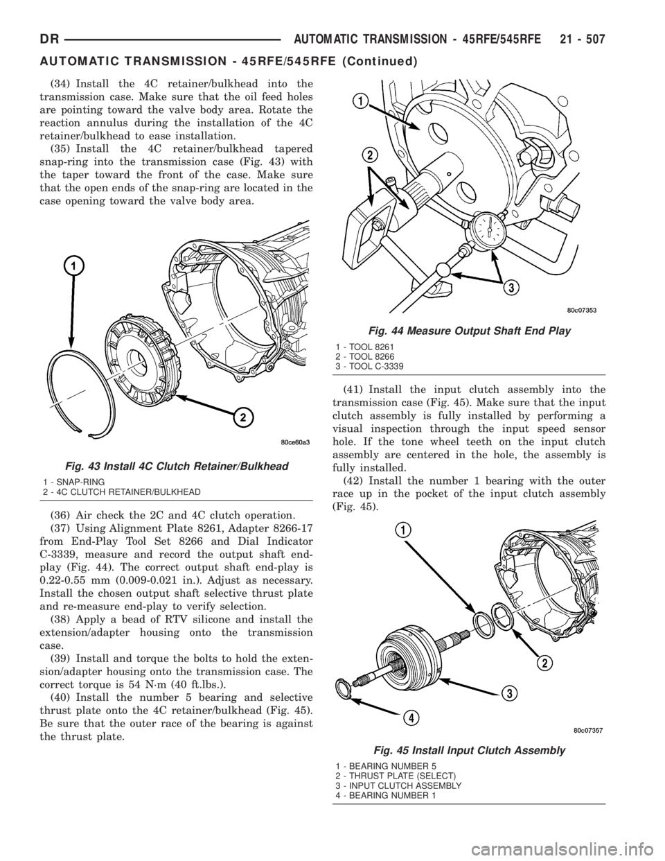
(35) Install the 4C retainer/bulkhead tapered
snap-ring into the transmission case (Fig. 43) with
the taper toward the front of the case. Make sure
that the open ends of the snap-ring are located in the
case opening toward the valve body area.
(36) Air check the 2C and 4C clutch operation.
(37) Using Alignment Plate 8261, Adapter 8266-17
from End-Play Tool Set 8266 and Dial Indicator
C-3339, measure and record the output shaft end-
play (Fig. 44). The correct output shaft end-play is
0.22-0.55 mm (0.009-0.021 in.). Adjust as necessary.
Install the chosen output shaft selective thrust plate
and re-measure end-play to verify selection.
(38) Apply a bead of RTV silicone and install the
extension/adapter housing onto the transmission
case.
(39) Install and torque the bolts to hold the exten-
sion/adapter housing onto the transmission case. The
correct torque is 54 N´m (40 ft.lbs.).
(40) Install the number 5 bearing and selective
thrust plate onto the 4C retainer/bulkhead (Fig. 45).
Be sure that the outer race of the bearing is against
the thrust plate.(41) Install the input clutch assembly into the
transmission case (Fig. 45). Make sure that the input
clutch assembly is fully installed by performing a
visual inspection through the input speed sensor
hole. If the tone wheel teeth on the input clutch
assembly are centered in the hole, the assembly is
fully installed.
(42) Install the number 1 bearing with the outer
race up in the pocket of the input clutch assembly
(Fig. 45).
Fig. 43 Install 4C Clutch Retainer/Bulkhead
1 - SNAP-RING
2 - 4C CLUTCH RETAINER/BULKHEAD
Fig. 44 Measure Output Shaft End Play
1 - TOOL 8261
2 - TOOL 8266
3 - TOOL C-3339
Fig. 45 Install Input Clutch Assembly
1 - BEARING NUMBER 5
2 - THRUST PLATE (SELECT)
3 - INPUT CLUTCH ASSEMBLY
4 - BEARING NUMBER 1
DRAUTOMATIC TRANSMISSION - 45RFE/545RFE 21 - 507
AUTOMATIC TRANSMISSION - 45RFE/545RFE (Continued)
Page 2348 of 2895
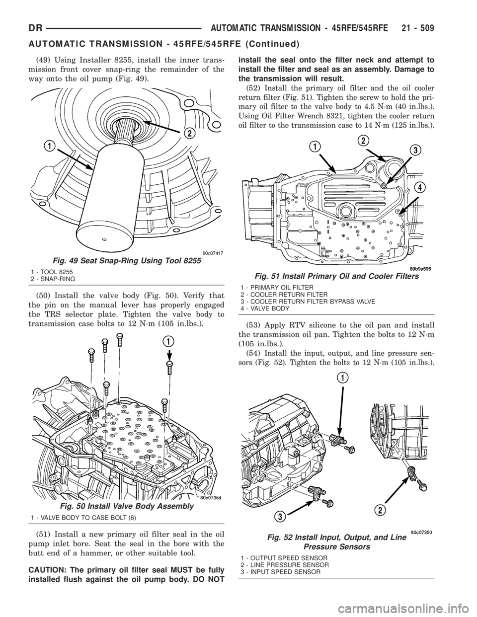
(49) Using Installer 8255, install the inner trans-
mission front cover snap-ring the remainder of the
way onto the oil pump (Fig. 49).
(50) Install the valve body (Fig. 50). Verify that
the pin on the manual lever has properly engaged
the TRS selector plate. Tighten the valve body to
transmission case bolts to 12 N´m (105 in.lbs.).
(51) Install a new primary oil filter seal in the oil
pump inlet bore. Seat the seal in the bore with the
butt end of a hammer, or other suitable tool.
CAUTION: The primary oil filter seal MUST be fully
installed flush against the oil pump body. DO NOTinstall the seal onto the filter neck and attempt to
install the filter and seal as an assembly. Damage to
the transmission will result.
(52)
Install the primary oil filter and the oil cooler
return filter (Fig. 51). Tighten the screw to hold the pri-
mary oil filter to the valve body to 4.5 N´m (40 in.lbs.).
Using Oil Filter Wrench 8321, tighten the cooler return
oil filter to the transmission case to 14 N´m (125 in.lbs.).
(53) Apply RTV silicone to the oil pan and install
the transmission oil pan. Tighten the bolts to 12 N´m
(105 in.lbs.).
(54)
Install the input, output, and line pressure sen-
sors (Fig. 52). Tighten the bolts to 12 N´m (105 in.lbs.).
Fig. 49 Seat Snap-Ring Using Tool 8255
1 - TOOL 8255
2 - SNAP-RING
Fig. 50 Install Valve Body Assembly
1 - VALVE BODY TO CASE BOLT (6)
Fig. 51 Install Primary Oil and Cooler Filters
1 - PRIMARY OIL FILTER
2 - COOLER RETURN FILTER
3 - COOLER RETURN FILTER BYPASS VALVE
4 - VALVE BODY
Fig. 52 Install Input, Output, and Line
Pressure Sensors
1 - OUTPUT SPEED SENSOR
2 - LINE PRESSURE SENSOR
3 - INPUT SPEED SENSOR
DRAUTOMATIC TRANSMISSION - 45RFE/545RFE 21 - 509
AUTOMATIC TRANSMISSION - 45RFE/545RFE (Continued)
Page 2350 of 2895
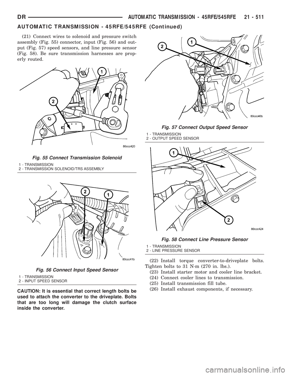
(21) Connect wires to solenoid and pressure switch
assembly (Fig. 55) connector, input (Fig. 56) and out-
put (Fig. 57) speed sensors, and line pressure sensor
(Fig. 58). Be sure transmission harnesses are prop-
erly routed.
CAUTION: It is essential that correct length bolts be
used to attach the converter to the driveplate. Bolts
that are too long will damage the clutch surface
inside the converter.(22) Install torque converter-to-driveplate bolts.
Tighten bolts to 31 N´m (270 in. lbs.).
(23) Install starter motor and cooler line bracket.
(24) Connect cooler lines to transmission.
(25) Install transmission fill tube.
(26) Install exhaust components, if necessary.
Fig. 55 Connect Transmission Solenoid
1 - TRANSMISSION
2 - TRANSMISSION SOLENOID/TRS ASSEMBLY
Fig. 56 Connect Input Speed Sensor
1 - TRANSMISSION
2 - INPUT SPEED SENSOR
Fig. 57 Connect Output Speed Sensor
1 - TRANSMISSION
2 - OUTPUT SPEED SENSOR
Fig. 58 Connect Line Pressure Sensor
1 - TRANSMISSION
2 - LINE PRESSURE SENSOR
DRAUTOMATIC TRANSMISSION - 45RFE/545RFE 21 - 511
AUTOMATIC TRANSMISSION - 45RFE/545RFE (Continued)
Page 2373 of 2895
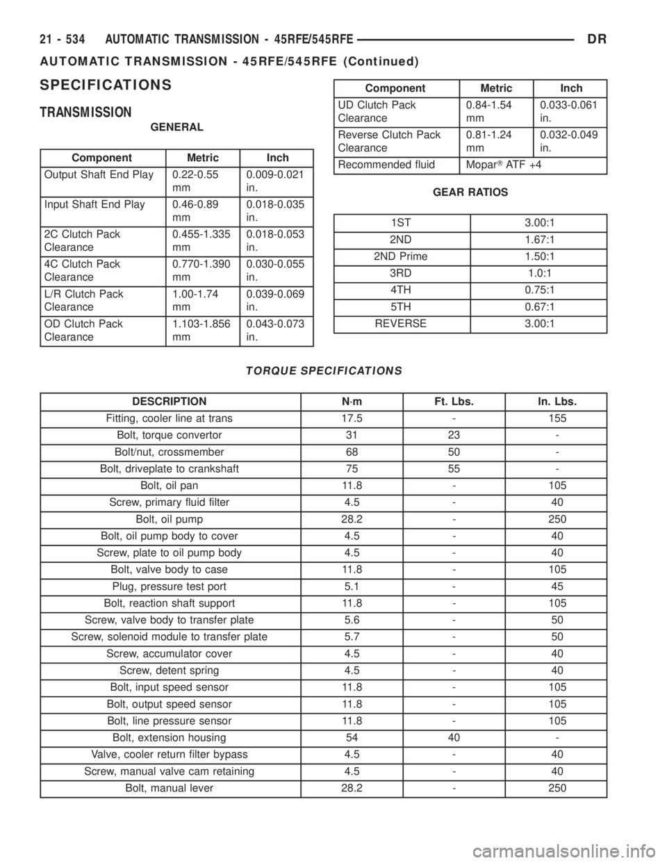
SPECIFICATIONS
TRANSMISSION
GENERAL
Component Metric Inch
Output Shaft End Play 0.22-0.55
mm0.009-0.021
in.
Input Shaft End Play 0.46-0.89
mm0.018-0.035
in.
2C Clutch Pack
Clearance0.455-1.335
mm0.018-0.053
in.
4C Clutch Pack
Clearance0.770-1.390
mm0.030-0.055
in.
L/R Clutch Pack
Clearance1.00-1.74
mm0.039-0.069
in.
OD Clutch Pack
Clearance1.103-1.856
mm0.043-0.073
in.
Component Metric Inch
UD Clutch Pack
Clearance0.84-1.54
mm0.033-0.061
in.
Reverse Clutch Pack
Clearance0.81-1.24
mm0.032-0.049
in.
Recommended fluid MoparTAT F + 4
GEAR RATIOS
1ST 3.00:1
2ND 1.67:1
2ND Prime 1.50:1
3RD 1.0:1
4TH 0.75:1
5TH 0.67:1
REVERSE 3.00:1
TORQUE SPECIFICATIONS
DESCRIPTION N´m Ft. Lbs. In. Lbs.
Fitting, cooler line at trans 17.5 - 155
Bolt, torque convertor 31 23 -
Bolt/nut, crossmember 68 50 -
Bolt, driveplate to crankshaft 75 55 -
Bolt, oil pan 11.8 - 105
Screw, primary fluid filter 4.5 - 40
Bolt, oil pump 28.2 - 250
Bolt, oil pump body to cover 4.5 - 40
Screw, plate to oil pump body 4.5 - 40
Bolt, valve body to case 11.8 - 105
Plug, pressure test port 5.1 - 45
Bolt, reaction shaft support 11.8 - 105
Screw, valve body to transfer plate 5.6 - 50
Screw, solenoid module to transfer plate 5.7 - 50
Screw, accumulator cover 4.5 - 40
Screw, detent spring 4.5 - 40
Bolt, input speed sensor 11.8 - 105
Bolt, output speed sensor 11.8 - 105
Bolt, line pressure sensor 11.8 - 105
Bolt, extension housing 54 40 -
Valve, cooler return filter bypass 4.5 - 40
Screw, manual valve cam retaining 4.5 - 40
Bolt, manual lever 28.2 - 250
21 - 534 AUTOMATIC TRANSMISSION - 45RFE/545RFEDR
AUTOMATIC TRANSMISSION - 45RFE/545RFE (Continued)
Page 2381 of 2895
²internal failure that generates debris
²overheat that generates sludge (fluid break-
down)
²failure to replace contaminated converter after
repair
The use of non-recommended fluids can result in
transmission failure. The usual results are erratic
shifts, slippage, abnormal wear and eventual failure
due to fluid breakdown and sludge formation. Avoid
this condition by using recommended fluids only.
The dipstick cap and fill tube should be wiped
clean before checking fluid level. Dirt, grease and
other foreign material on the cap and tube could fall
into the tube if not removed beforehand. Take the
time to wipe the cap and tube clean before withdraw-
ing the dipstick.
Engine coolant in the transmission fluid is gener-
ally caused by a cooler malfunction. The only remedy
is to replace the radiator as the cooler in the radiator
is not a serviceable part. If coolant has circulated
through the transmission, an overhaul is necessary.
The torque converter should be replaced whenever
a failure generates sludge and debris. This is neces-
sary because normal converter flushing procedures
will not remove all contaminants.
STANDARD PROCEDURE
STANDARD PROCEDURE - FLUID LEVEL
CHECK
Low fluid level can cause a variety of conditions
because it allows the pump to take in air along with
the fluid. As in any hydraulic system, air bubbles
make the fluid spongy, therefore, pressures will be
low and build up slowly.
Improper filling can also raise the fluid level too
high. When the transmssion has too much fluid, the
geartrain churns up foam and cause the same condi-
tions which occur with a low fluid level.
In either case, air bubbles can cause overheating
and/or fluid oxidation, and varnishing. This can
interfere with normal valve, clutch, and accumulator
operation. Foaming can also result in fluid escaping
from the transmission vent where it may be mis-
taken for a leak.
After the fluid has been checked, seat the dipstick
fully to seal out water and dirt.
The transmission has a dipstick to check oil level.
It is located on the right side of the engine. Be sure
to wipe all dirt from dipstick handle before removing.
The torque converter fills in both the P (PARK)
and N (NEUTRAL) positions. Place the selector lever
in P (PARK) to be sure that the fluid level check is
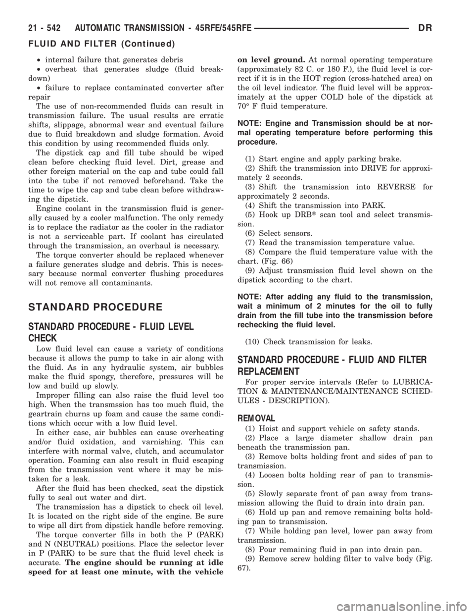
accurate.The engine should be running at idle
speed for at least one minute, with the vehicleon level ground.At normal operating temperature
(approximately 82 C. or 180 F.), the fluid level is cor-
rect if it is in the HOT region (cross-hatched area) on
the oil level indicator. The fluid level will be approx-
imately at the upper COLD hole of the dipstick at
70É F fluid temperature.
NOTE: Engine and Transmission should be at nor-
mal operating temperature before performing this
procedure.
(1) Start engine and apply parking brake.
(2) Shift the transmission into DRIVE for approxi-
mately 2 seconds.
(3) Shift the transmission into REVERSE for
approximately 2 seconds.
(4) Shift the transmission into PARK.
(5) Hook up DRBtscan tool and select transmis-
sion.
(6) Select sensors.
(7) Read the transmission temperature value.
(8) Compare the fluid temperature value with the
chart. (Fig. 66)
(9) Adjust transmission fluid level shown on the
dipstick according to the chart.
NOTE: After adding any fluid to the transmission,
wait a minimum of 2 minutes for the oil to fully
drain from the fill tube into the transmission before
rechecking the fluid level.
(10) Check transmission for leaks.
STANDARD PROCEDURE - FLUID AND FILTER
REPLACEMENT
For proper service intervals (Refer to LUBRICA-
TION & MAINTENANCE/MAINTENANCE SCHED-
ULES - DESCRIPTION).
REMOVAL
(1) Hoist and support vehicle on safety stands.
(2) Place a large diameter shallow drain pan
beneath the transmission pan.
(3) Remove bolts holding front and sides of pan to
transmission.
(4) Loosen bolts holding rear of pan to transmis-
sion.
(5) Slowly separate front of pan away from trans-
mission allowing the fluid to drain into drain pan.
(6) Hold up pan and remove remaining bolts hold-
ing pan to transmission.
(7) While holding pan level, lower pan away from
transmission.
(8) Pour remaining fluid in pan into drain pan.
(9) Remove screw holding filter to valve body (Fig.
67).
21 - 542 AUTOMATIC TRANSMISSION - 45RFE/545RFEDR
FLUID AND FILTER (Continued)
Page 2397 of 2895
(24) Install the reverse reaction plate into the
input clutch retainer.
(25) Install the reverse reaction plate selective
snap-ring into the input clutch retainer.
(26) Mount a dial indicator to the assembly, push
down on the clutch discs, pull up on the reaction
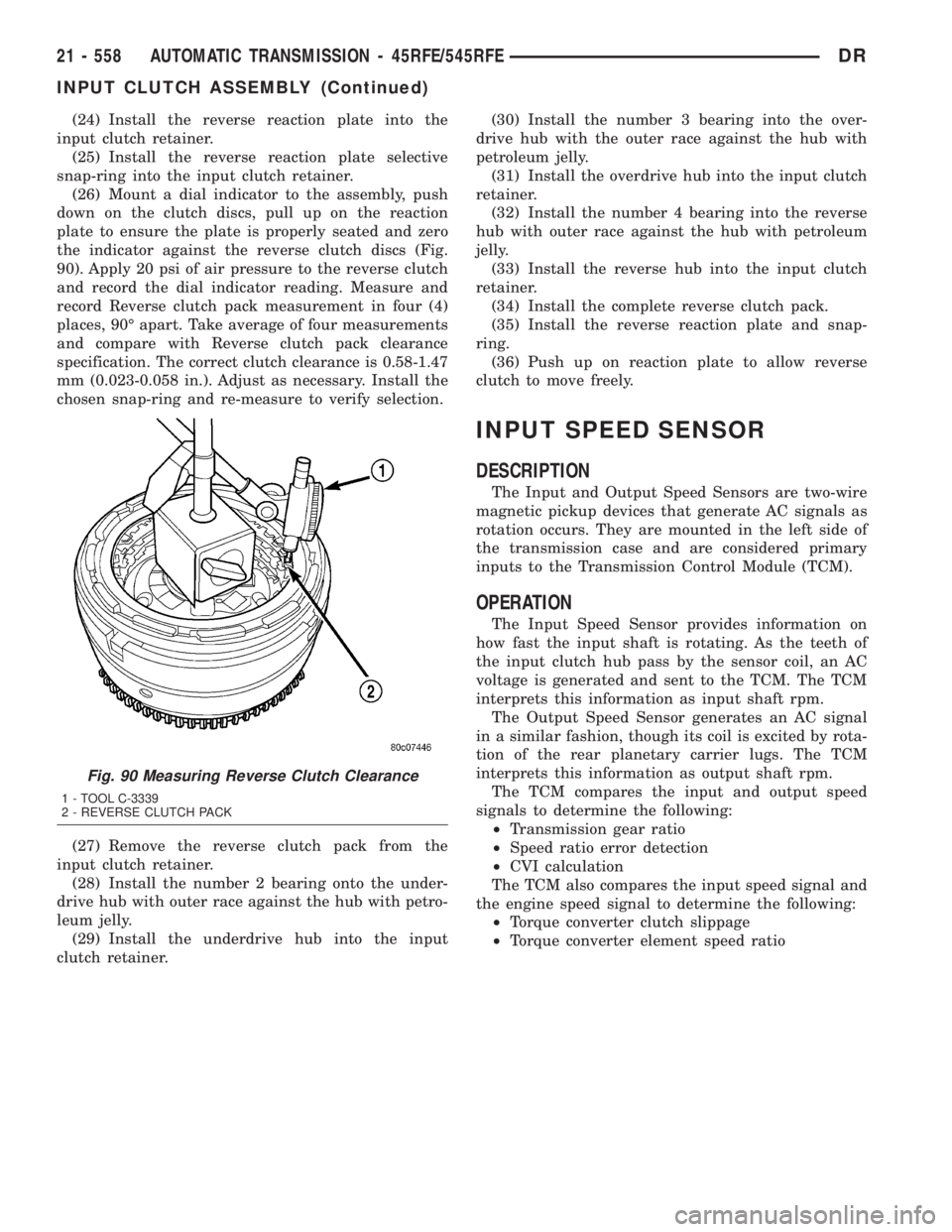
plate to ensure the plate is properly seated and zero
the indicator against the reverse clutch discs (Fig.
90). Apply 20 psi of air pressure to the reverse clutch
and record the dial indicator reading. Measure and
record Reverse clutch pack measurement in four (4)
places, 90É apart. Take average of four measurements
and compare with Reverse clutch pack clearance
specification. The correct clutch clearance is 0.58-1.47
mm (0.023-0.058 in.). Adjust as necessary. Install the
chosen snap-ring and re-measure to verify selection.
(27) Remove the reverse clutch pack from the
input clutch retainer.
(28) Install the number 2 bearing onto the under-
drive hub with outer race against the hub with petro-
leum jelly.
(29) Install the underdrive hub into the input
clutch retainer.(30) Install the number 3 bearing into the over-
drive hub with the outer race against the hub with
petroleum jelly.
(31) Install the overdrive hub into the input clutch
retainer.
(32) Install the number 4 bearing into the reverse
hub with outer race against the hub with petroleum
jelly.
(33) Install the reverse hub into the input clutch
retainer.
(34) Install the complete reverse clutch pack.
(35) Install the reverse reaction plate and snap-
ring.
(36) Push up on reaction plate to allow reverse
clutch to move freely.
INPUT SPEED SENSOR
DESCRIPTION
The Input and Output Speed Sensors are two-wire
magnetic pickup devices that generate AC signals as
rotation occurs. They are mounted in the left side of
the transmission case and are considered primary
inputs to the Transmission Control Module (TCM).
OPERATION
The Input Speed Sensor provides information on
how fast the input shaft is rotating. As the teeth of
the input clutch hub pass by the sensor coil, an AC
voltage is generated and sent to the TCM. The TCM
interprets this information as input shaft rpm.
The Output Speed Sensor generates an AC signal
in a similar fashion, though its coil is excited by rota-
tion of the rear planetary carrier lugs. The TCM
interprets this information as output shaft rpm.
The TCM compares the input and output speed
signals to determine the following:
²Transmission gear ratio
²Speed ratio error detection
²CVI calculation
The TCM also compares the input speed signal and
the engine speed signal to determine the following:
²Torque converter clutch slippage
²Torque converter element speed ratio
Fig. 90 Measuring Reverse Clutch Clearance
1 - TOOL C-3339
2 - REVERSE CLUTCH PACK
21 - 558 AUTOMATIC TRANSMISSION - 45RFE/545RFEDR
INPUT CLUTCH ASSEMBLY (Continued)
Page 2398 of 2895
REMOVAL
(1) Raise vehicle.
(2) Place a suitable fluid catch pan under the
transmission.
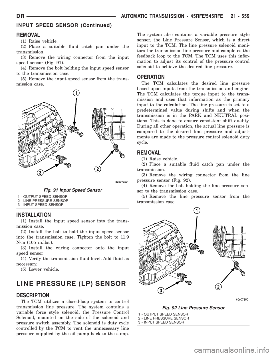
(3) Remove the wiring connector from the input
speed sensor (Fig. 91).
(4) Remove the bolt holding the input speed sensor
to the transmission case.
(5) Remove the input speed sensor from the trans-
mission case.
INSTALLATION
(1) Install the input speed sensor into the trans-
mission case.
(2) Install the bolt to hold the input speed sensor
into the transmission case. Tighten the bolt to 11.9
N´m (105 in.lbs.).
(3) Install the wiring connector onto the input
speed sensor
(4) Verify the transmission fluid level. Add fluid as
necessary.
(5) Lower vehicle.
LINE PRESSURE (LP) SENSOR
DESCRIPTION
The TCM utilizes a closed-loop system to control
transmission line pressure. The system contains a
variable force style solenoid, the Pressure Control
Solenoid, mounted on the side of the solenoid and
pressure switch assembly. The solenoid is duty cycle
controlled by the TCM to vent the unnecessary line
pressure supplied by the oil pump back to the sump.The system also contains a variable pressure style
sensor, the Line Pressure Sensor, which is a direct
input to the TCM. The line pressure solenoid moni-
tors the transmission line pressure and completes the
feedback loop to the TCM. The TCM uses this infor-
mation to adjust its control of the pressure control
solenoid to achieve the desired line pressure.
OPERATION
The TCM calculates the desired line pressure
based upon inputs from the transmission and engine.
The TCM calculates the torque input to the trans-
mission and uses that information as the primary
input to the calculation. The line pressure is set to a
predetermined value during shifts and when the
transmission is in the PARK and NEUTRAL posi-
tions. This is done to ensure consistent shift quality.
During all other operation, the actual line pressure is
compared to the desired line pressure and adjust-
ments are made to the pressure control solenoid duty
cycle.
REMOVAL
(1) Raise vehicle.
(2) Place a suitable fluid catch pan under the
transmission.
(3) Remove the wiring connector from the line
pressure sensor (Fig. 92).
(4) Remove the bolt holding the line pressure sen-
sor to the transmission case.
(5) Remove the line pressure sensor from the
transmission case.
Fig. 91 Input Speed Sensor
1 - OUTPUT SPEED SENSOR
2 - LINE PRESSURE SENSOR
3 - INPUT SPEED SENSOR
Fig. 92 Line Pressure Sensor
1 - OUTPUT SPEED SENSOR
2 - LINE PRESSURE SENSOR
3 - INPUT SPEED SENSOR
DRAUTOMATIC TRANSMISSION - 45RFE/545RFE 21 - 559
INPUT SPEED SENSOR (Continued)