2003 DODGE RAM Speed sensor
[x] Cancel search: Speed sensorPage 1174 of 2895
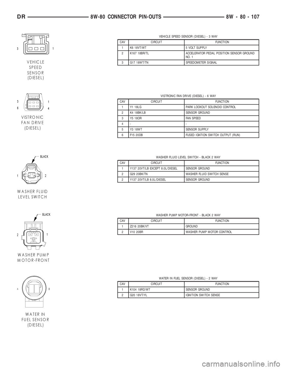
VEHICLE SPEED SENSOR (DIESEL)-3WAY
CAV CIRCUIT FUNCTION
1 K6 18VT/WT 5 VOLT SUPPLY
2 K167 18BR/TL ACCELERATOR PEDAL POSITION SENSOR GROUND
NO. 1
3 G17 18WT/TN SPEEDOMETER SIGNAL
VISTRONIC FAN DRIVE (DIESEL)-6WAY
CAV CIRCUIT FUNCTION
1 Y1 18LG PARK LOCKOUT SOLENOID CONTROL
2 K4 18BK/LB SENSOR GROUND
3 Y5 18OR FAN SPEED
4- -
5 Y3 18WT SENSOR SUPPLY
6 F15 20DB FUSED IGNTION SWITCH OUTPUT (RUN)
WASHER FLUID LEVEL SWITCH - BLACK 2 WAY
CAV CIRCUIT FUNCTION
1 Y137 20VT/LB EXCEPT 8.0L/DIESEL SENSOR GROUND
2 G29 20BK/TN WASHER FLUID SWITCH SENSE
2 Y137 20VT/LB 8.0L/DIESEL SENSOR GROUND
WASHER PUMP MOTOR-FRONT - BLACK 2 WAY
CAV CIRCUIT FUNCTION
1 Z216 20BK/VT GROUND
2 V10 20BR WASHER PUMP MOTOR CONTROL
WATER IN FUEL SENSOR (DIESEL)-2WAY
CAV CIRCUIT FUNCTION
1 K104 18RD/WT SENSOR GROUND
2 G20 18VT/YL IGNITION SWITCH SENSE
DR8W-80 CONNECTOR PIN-OUTS 8W - 80 - 107
Page 1175 of 2895
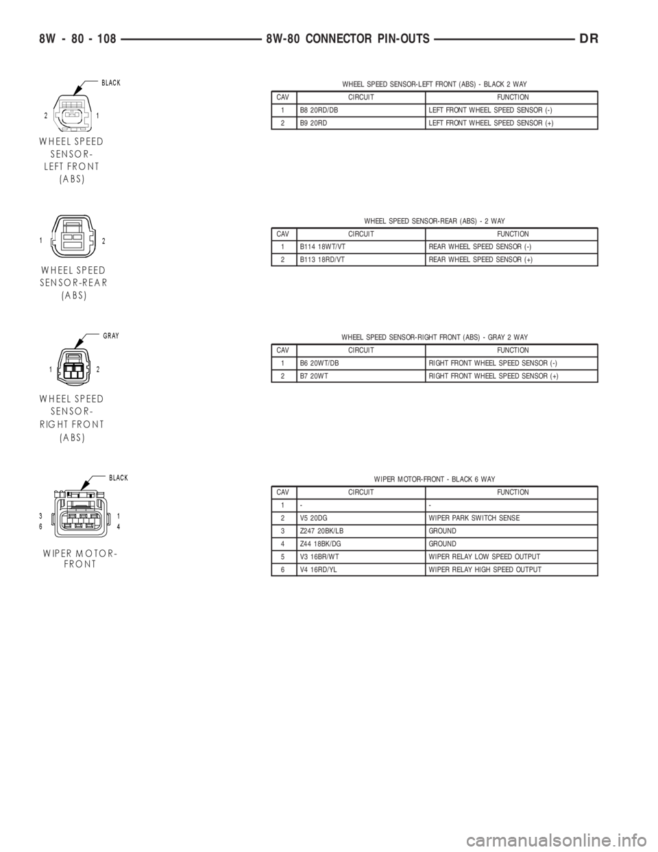
WHEEL SPEED SENSOR-LEFT FRONT (ABS) - BLACK 2 WAY
CAV CIRCUIT FUNCTION
1 B8 20RD/DB LEFT FRONT WHEEL SPEED SENSOR (-)
2 B9 20RD LEFT FRONT WHEEL SPEED SENSOR (+)
WHEEL SPEED SENSOR-REAR (ABS)-2WAY
CAV CIRCUIT FUNCTION
1 B114 18WT/VT REAR WHEEL SPEED SENSOR (-)
2 B113 18RD/VT REAR WHEEL SPEED SENSOR (+)
WHEEL SPEED SENSOR-RIGHT FRONT (ABS) - GRAY 2 WAY
CAV CIRCUIT FUNCTION
1 B6 20WT/DB RIGHT FRONT WHEEL SPEED SENSOR (-)
2 B7 20WT RIGHT FRONT WHEEL SPEED SENSOR (+)
WIPER MOTOR-FRONT - BLACK 6 WAY
CAV CIRCUIT FUNCTION
1- -
2 V5 20DG WIPER PARK SWITCH SENSE
3 Z247 20BK/LB GROUND
4 Z44 18BK/DG GROUND
5 V3 16BR/WT WIPER RELAY LOW SPEED OUTPUT
6 V4 16RD/YL WIPER RELAY HIGH SPEED OUTPUT
8W - 80 - 108 8W-80 CONNECTOR PIN-OUTSDR
Page 1176 of 2895
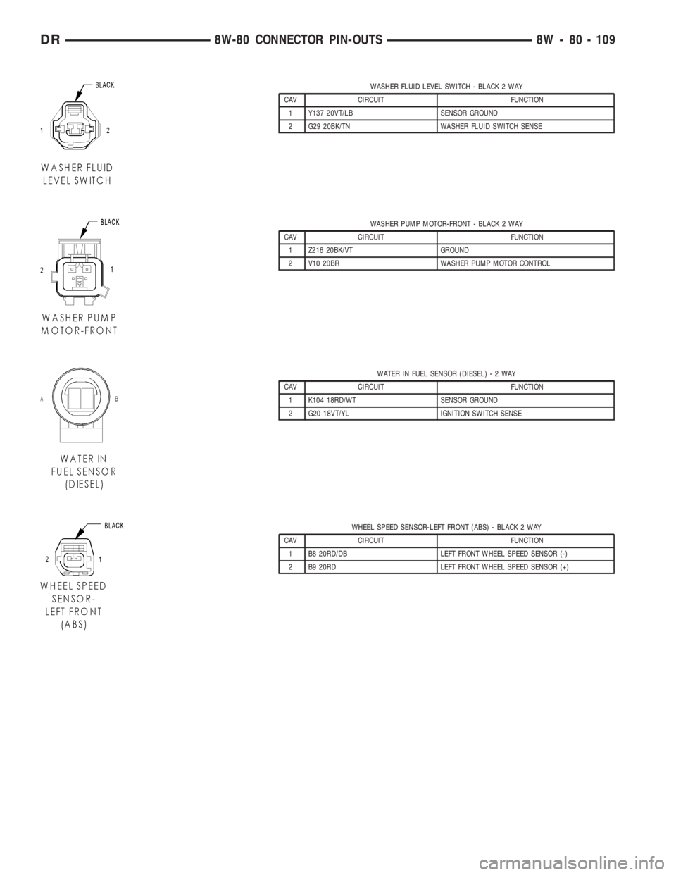
WASHER FLUID LEVEL SWITCH - BLACK 2 WAY
CAV CIRCUIT FUNCTION
1 Y137 20VT/LB SENSOR GROUND
2 G29 20BK/TN WASHER FLUID SWITCH SENSE
WASHER PUMP MOTOR-FRONT - BLACK 2 WAY
CAV CIRCUIT FUNCTION
1 Z216 20BK/VT GROUND
2 V10 20BR WASHER PUMP MOTOR CONTROL
WATER IN FUEL SENSOR (DIESEL)-2WAY
CAV CIRCUIT FUNCTION
1 K104 18RD/WT SENSOR GROUND
2 G20 18VT/YL IGNITION SWITCH SENSE
WHEEL SPEED SENSOR-LEFT FRONT (ABS) - BLACK 2 WAY
CAV CIRCUIT FUNCTION
1 B8 20RD/DB LEFT FRONT WHEEL SPEED SENSOR (-)
2 B9 20RD LEFT FRONT WHEEL SPEED SENSOR (+)
DR8W-80 CONNECTOR PIN-OUTS 8W - 80 - 109
Page 1177 of 2895
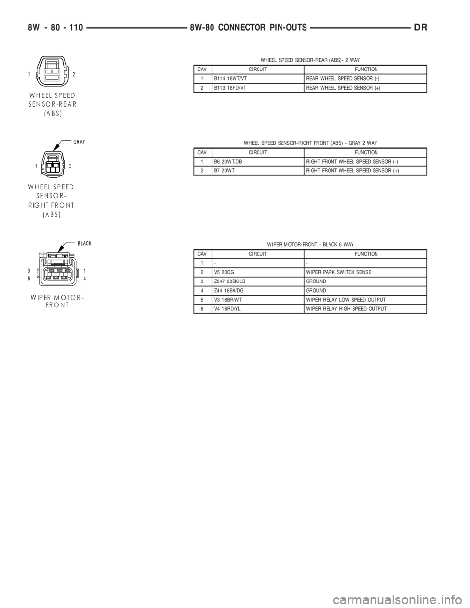
WHEEL SPEED SENSOR-REAR (ABS)- 2 WAY
CAV CIRCUIT FUNCTION
1 B114 18WT/VT REAR WHEEL SPEED SENSOR (-)
2 B113 18RD/VT REAR WHEEL SPEED SENSOR (+)
WHEEL SPEED SENSOR-RIGHT FRONT (ABS) - GRAY 2 WAY
CAV CIRCUIT FUNCTION
1 B6 20WT/DB RIGHT FRONT WHEEL SPEED SENSOR (-)
2 B7 20WT RIGHT FRONT WHEEL SPEED SENSOR (+)
WIPER MOTOR-FRONT - BLACK 6 WAY
CAV CIRCUIT FUNCTION
1- -
2 V5 20DG WIPER PARK SWITCH SENSE
3 Z247 20BK/LB GROUND
4 Z44 18BK/DG GROUND
5 V3 16BR/WT WIPER RELAY LOW SPEED OUTPUT
6 V4 16RD/YL WIPER RELAY HIGH SPEED OUTPUT
8W - 80 - 110 8W-80 CONNECTOR PIN-OUTSDR
Page 1182 of 2895
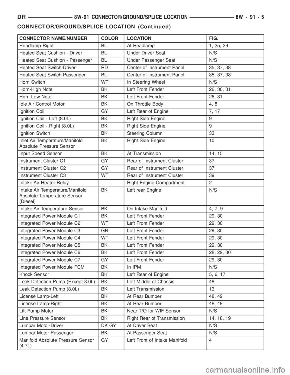
CONNECTOR NAME/NUMBER COLOR LOCATION FIG.
Headlamp-Right BL At Headlamp 1, 25, 29
Heated Seat Cushion - Driver BL Under Driver Seat N/S
Heated Seat Cushion - Passenger BL Under Passenger Seat N/S
Heated Seat Switch-Driver RD Center of Instrument Panel 35, 37, 38
Heated Seat Switch-Passenger BL Center of Instrument Panel 35, 37, 38
Horn Switch WT In Steering Wheel N/S
Horn-High Note BK Left Front Fender 26, 30, 31
Horn-Low Note BK Left Front Fender 26, 31
Idle Air Control Motor BK On Throttle Body 4, 8
Ignition Coil GY Left Rear of Engine 7, 17
Ignition Coil - Left (8.0L) BK Right Side Engine 9
Ignition Coil - Right (8.0L) BK Right Side Engine 9
Ignition Switch BK Steering Column 33
Inlet Air Temperature/Manifold
Absolute Pressure SensorBK Right Side Engine 10
Input Speed Sensor BK At Transmission 14, 15
Instrument Cluster C1 GY Rear of Instrument Cluster 37
Instrument Cluster C2 GY Rear of Instrument Cluster 37
Instrument Cluster C3 WT Rear of Instrument Cluster 39
Intake Air Heater Relay Right Engine Compartment 2
Intake Air Temperature/Manifold
Absolute Temperature Sensor
(Diesel)BK Left rear Engine N/S
Intake Air Temperature Sensor BK On Intake Manifold 4, 7, 9
Integrated Power Module C1 BK Left Front Fender 29, 30
Integrated Power Module C2 WT Left Front Fender 29, 30
Integrated Power Module C3 GR Left Front Fender 29, 30
Integrated Power Module C4 WT Left Front Fender 29, 30
Integrated Power Module C5 BK Left Front Fender 29, 30
Integrated Power Module C6 BK Left Front Fender 28, 29, 30
Integrated Power Module C7 GY Left Front Fender 29, 30
Integrated Power Module FCM BK In IPM N/S
Knock Sensor BK Left Rear of Engine 5, 6, 17
Leak Detection Pump (Except 8.0L) BK Left Middle of Chassis 48
Leak Detection Pump (8.0L) BK Left Transmission 13
License Lamp-Left BK At Rear Bumper 48, 49
License Lamp-Right BK At Rear Bumper 48, 49
Lift Pump Motor BK Near T/O for WIF Sensor N/S
Line Pressure Sensor BK Right Rear of Transmission 14, 18, 19
Lumbar Motor-Driver DK GY At Driver Seat N/S
Lumbar Motor-Passenger BK At Passenger Seat N/S
Manifold Absolute Pressure Sensor
(4.7L)GY Left Front of Intake Manifold 4
DR8W-91 CONNECTOR/GROUND/SPLICE LOCATION 8W - 91 - 5
CONNECTOR/GROUND/SPLICE LOCATION (Continued)
Page 1183 of 2895
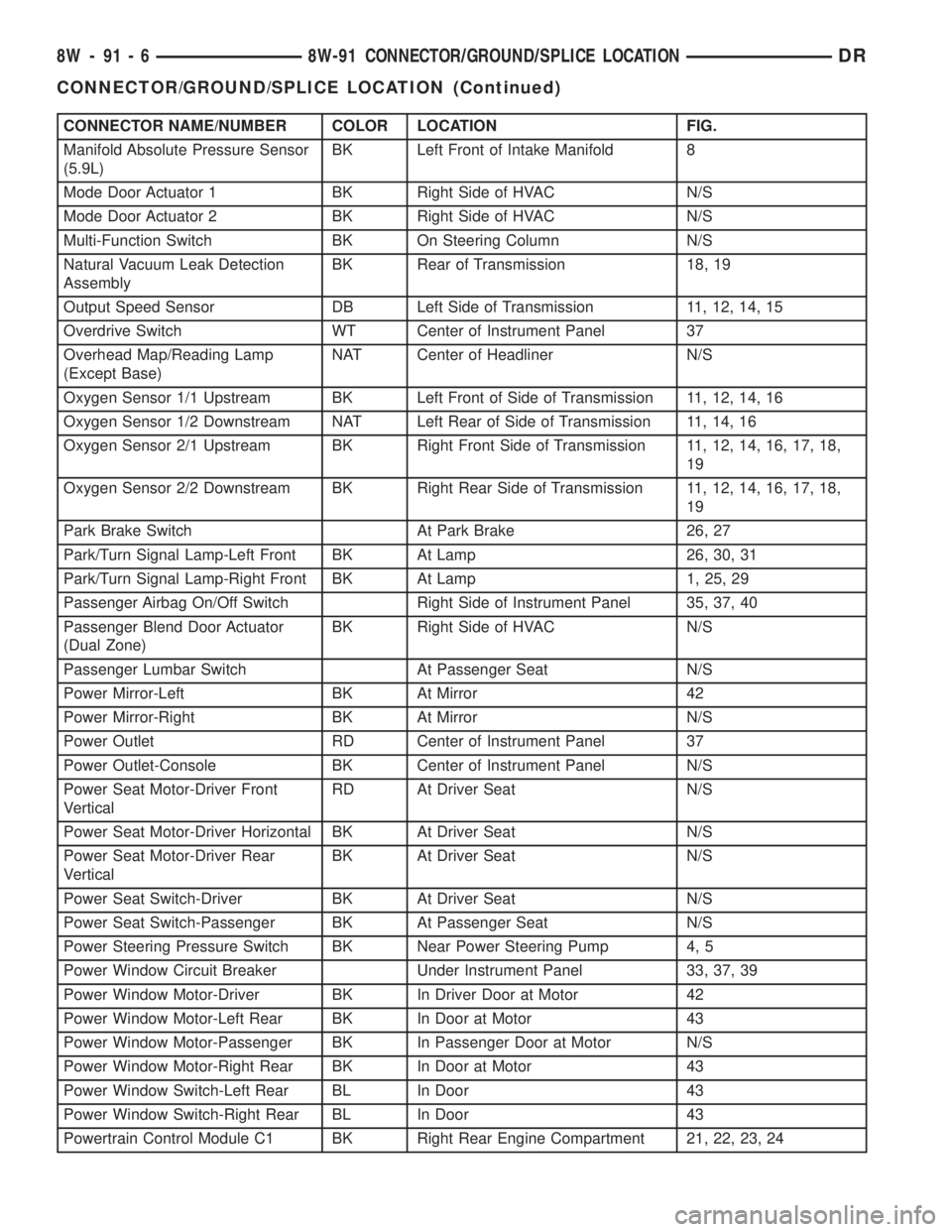
CONNECTOR NAME/NUMBER COLOR LOCATION FIG.
Manifold Absolute Pressure Sensor
(5.9L)BK Left Front of Intake Manifold 8
Mode Door Actuator 1 BK Right Side of HVAC N/S
Mode Door Actuator 2 BK Right Side of HVAC N/S
Multi-Function Switch BK On Steering Column N/S
Natural Vacuum Leak Detection
AssemblyBK Rear of Transmission 18, 19
Output Speed Sensor DB Left Side of Transmission 11, 12, 14, 15
Overdrive Switch WT Center of Instrument Panel 37
Overhead Map/Reading Lamp
(Except Base)NAT Center of Headliner N/S
Oxygen Sensor 1/1 Upstream BK Left Front of Side of Transmission 11, 12, 14, 16
Oxygen Sensor 1/2 Downstream NAT Left Rear of Side of Transmission 11, 14, 16
Oxygen Sensor 2/1 Upstream BK Right Front Side of Transmission 11, 12, 14, 16, 17, 18,
19
Oxygen Sensor 2/2 Downstream BK Right Rear Side of Transmission 11, 12, 14, 16, 17, 18,
19
Park Brake Switch At Park Brake 26, 27
Park/Turn Signal Lamp-Left Front BK At Lamp 26, 30, 31
Park/Turn Signal Lamp-Right Front BK At Lamp 1, 25, 29
Passenger Airbag On/Off Switch Right Side of Instrument Panel 35, 37, 40
Passenger Blend Door Actuator
(Dual Zone)BK Right Side of HVAC N/S
Passenger Lumbar Switch At Passenger Seat N/S
Power Mirror-Left BK At Mirror 42
Power Mirror-Right BK At Mirror N/S
Power Outlet RD Center of Instrument Panel 37
Power Outlet-Console BK Center of Instrument Panel N/S
Power Seat Motor-Driver Front
VerticalRD At Driver Seat N/S
Power Seat Motor-Driver Horizontal BK At Driver Seat N/S
Power Seat Motor-Driver Rear
VerticalBK At Driver Seat N/S
Power Seat Switch-Driver BK At Driver Seat N/S
Power Seat Switch-Passenger BK At Passenger Seat N/S
Power Steering Pressure Switch BK Near Power Steering Pump 4, 5
Power Window Circuit Breaker Under Instrument Panel 33, 37, 39
Power Window Motor-Driver BK In Driver Door at Motor 42
Power Window Motor-Left Rear BK In Door at Motor 43
Power Window Motor-Passenger BK In Passenger Door at Motor N/S
Power Window Motor-Right Rear BK In Door at Motor 43
Power Window Switch-Left Rear BL In Door 43
Power Window Switch-Right Rear BL In Door 43
Powertrain Control Module C1 BK Right Rear Engine Compartment 21, 22, 23, 24
8W - 91 - 6 8W-91 CONNECTOR/GROUND/SPLICE LOCATIONDR
CONNECTOR/GROUND/SPLICE LOCATION (Continued)
Page 1185 of 2895
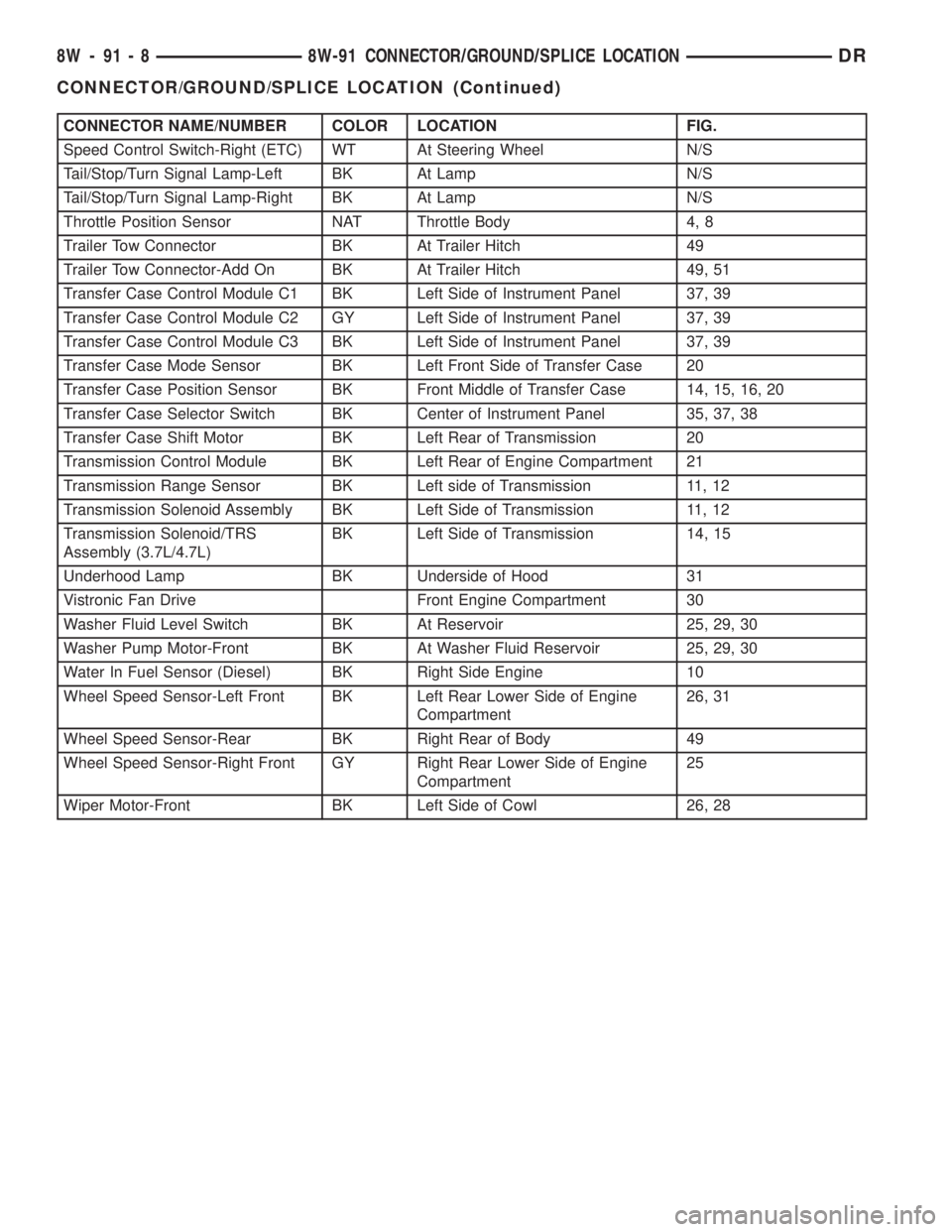
CONNECTOR NAME/NUMBER COLOR LOCATION FIG.
Speed Control Switch-Right (ETC) WT At Steering Wheel N/S
Tail/Stop/Turn Signal Lamp-Left BK At Lamp N/S
Tail/Stop/Turn Signal Lamp-Right BK At Lamp N/S
Throttle Position Sensor NAT Throttle Body 4, 8
Trailer Tow Connector BK At Trailer Hitch 49
Trailer Tow Connector-Add On BK At Trailer Hitch 49, 51
Transfer Case Control Module C1 BK Left Side of Instrument Panel 37, 39
Transfer Case Control Module C2 GY Left Side of Instrument Panel 37, 39
Transfer Case Control Module C3 BK Left Side of Instrument Panel 37, 39
Transfer Case Mode Sensor BK Left Front Side of Transfer Case 20
Transfer Case Position Sensor BK Front Middle of Transfer Case 14, 15, 16, 20
Transfer Case Selector Switch BK Center of Instrument Panel 35, 37, 38
Transfer Case Shift Motor BK Left Rear of Transmission 20
Transmission Control Module BK Left Rear of Engine Compartment 21
Transmission Range Sensor BK Left side of Transmission 11, 12
Transmission Solenoid Assembly BK Left Side of Transmission 11, 12
Transmission Solenoid/TRS
Assembly (3.7L/4.7L)BK Left Side of Transmission 14, 15
Underhood Lamp BK Underside of Hood 31
Vistronic Fan Drive Front Engine Compartment 30
Washer Fluid Level Switch BK At Reservoir 25, 29, 30
Washer Pump Motor-Front BK At Washer Fluid Reservoir 25, 29, 30
Water In Fuel Sensor (Diesel) BK Right Side Engine 10
Wheel Speed Sensor-Left Front BK Left Rear Lower Side of Engine
Compartment26, 31
Wheel Speed Sensor-Rear BK Right Rear of Body 49
Wheel Speed Sensor-Right Front GY Right Rear Lower Side of Engine
Compartment25
Wiper Motor-Front BK Left Side of Cowl 26, 28
8W - 91 - 8 8W-91 CONNECTOR/GROUND/SPLICE LOCATIONDR
CONNECTOR/GROUND/SPLICE LOCATION (Continued)
Page 1260 of 2895
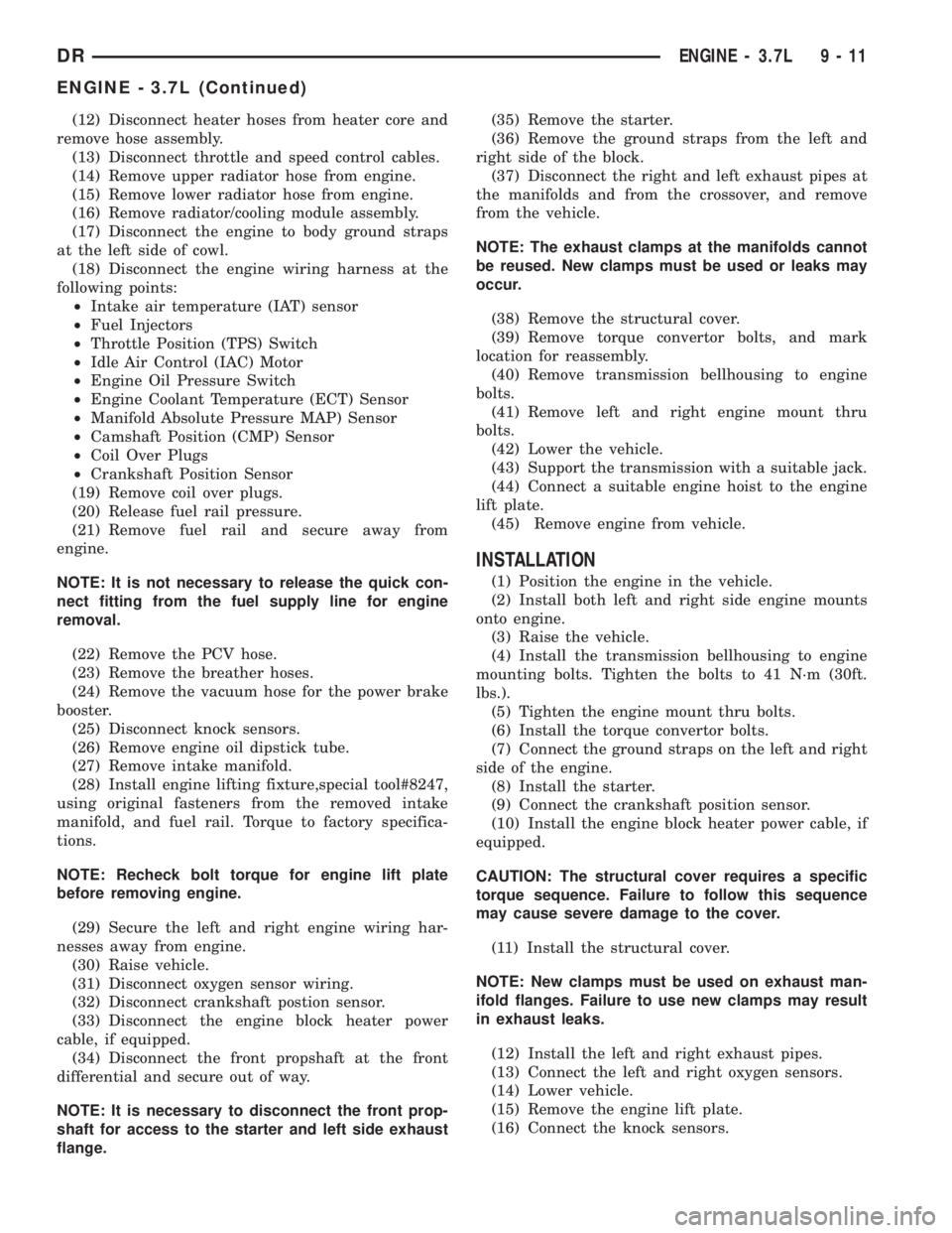
(12) Disconnect heater hoses from heater core and
remove hose assembly.
(13) Disconnect throttle and speed control cables.
(14) Remove upper radiator hose from engine.
(15) Remove lower radiator hose from engine.
(16) Remove radiator/cooling module assembly.
(17) Disconnect the engine to body ground straps
at the left side of cowl.
(18) Disconnect the engine wiring harness at the
following points:
²Intake air temperature (IAT) sensor
²Fuel Injectors
²Throttle Position (TPS) Switch
²Idle Air Control (IAC) Motor
²Engine Oil Pressure Switch
²Engine Coolant Temperature (ECT) Sensor
²Manifold Absolute Pressure MAP) Sensor
²Camshaft Position (CMP) Sensor
²Coil Over Plugs
²Crankshaft Position Sensor
(19) Remove coil over plugs.
(20) Release fuel rail pressure.
(21) Remove fuel rail and secure away from
engine.
NOTE: It is not necessary to release the quick con-
nect fitting from the fuel supply line for engine
removal.
(22) Remove the PCV hose.
(23) Remove the breather hoses.
(24) Remove the vacuum hose for the power brake
booster.
(25) Disconnect knock sensors.
(26) Remove engine oil dipstick tube.
(27) Remove intake manifold.
(28) Install engine lifting fixture,special tool#8247,
using original fasteners from the removed intake
manifold, and fuel rail. Torque to factory specifica-
tions.
NOTE: Recheck bolt torque for engine lift plate
before removing engine.
(29) Secure the left and right engine wiring har-
nesses away from engine.
(30) Raise vehicle.
(31) Disconnect oxygen sensor wiring.
(32) Disconnect crankshaft postion sensor.
(33) Disconnect the engine block heater power
cable, if equipped.
(34) Disconnect the front propshaft at the front
differential and secure out of way.
NOTE: It is necessary to disconnect the front prop-
shaft for access to the starter and left side exhaust
flange.(35) Remove the starter.
(36) Remove the ground straps from the left and
right side of the block.
(37) Disconnect the right and left exhaust pipes at
the manifolds and from the crossover, and remove
from the vehicle.
NOTE: The exhaust clamps at the manifolds cannot
be reused. New clamps must be used or leaks may
occur.
(38) Remove the structural cover.
(39) Remove torque convertor bolts, and mark
location for reassembly.
(40) Remove transmission bellhousing to engine
bolts.
(41) Remove left and right engine mount thru
bolts.
(42) Lower the vehicle.
(43) Support the transmission with a suitable jack.
(44) Connect a suitable engine hoist to the engine
lift plate.
(45) Remove engine from vehicle.
INSTALLATION
(1) Position the engine in the vehicle.
(2) Install both left and right side engine mounts
onto engine.
(3) Raise the vehicle.
(4) Install the transmission bellhousing to engine
mounting bolts. Tighten the bolts to 41 N´m (30ft.
lbs.).
(5) Tighten the engine mount thru bolts.
(6) Install the torque convertor bolts.
(7) Connect the ground straps on the left and right
side of the engine.
(8) Install the starter.
(9) Connect the crankshaft position sensor.
(10) Install the engine block heater power cable, if
equipped.
CAUTION: The structural cover requires a specific
torque sequence. Failure to follow this sequence
may cause severe damage to the cover.
(11) Install the structural cover.
NOTE: New clamps must be used on exhaust man-
ifold flanges. Failure to use new clamps may result
in exhaust leaks.
(12) Install the left and right exhaust pipes.
(13) Connect the left and right oxygen sensors.
(14) Lower vehicle.
(15) Remove the engine lift plate.
(16) Connect the knock sensors.
DRENGINE - 3.7L 9 - 11
ENGINE - 3.7L (Continued)