2003 DODGE RAM seats
[x] Cancel search: seatsPage 1600 of 2895
ENGINE 8.0L
TABLE OF CONTENTS
page page
ENGINE 8.0L
DESCRIPTION........................353
DIAGNOSIS AND TESTING
DIAGNOSIS AND TESTING - ENGINE
DIAGNOSIS - INTRODUCTION..........353
DIAGNOSIS AND TESTINGÐENGINE
DIAGNOSIS - PERFORMANCE..........354
DIAGNOSIS AND TESTING - ENGINE
DIAGNOSIS - MECHANICAL............356
DIAGNOSIS AND TESTINGÐENGINE
DIAGNOSIS - LUBRICATION............358
DIAGNOSIS AND TESTINGÐCYLINDER
COMPRESSION PRESSURE............359
DIAGNOSIS AND TESTING - CYLINDER
COMBUSTION PRESSURE LEAKAGE.....359
STANDARD PROCEDURE
STANDARD PROCEDUREÐCYLINDER
BORE HONING......................360
STANDARD PROCEDURE - FORM-IN-
PLACE GASKETS AND SEALERS........360
STANDARD PROCEDURE - REPAIR
DAMAGED OR WORN THREADS........361
STANDARD PROCEDUREÐHYDROSTATIC
LOCK..............................361
REMOVAL............................361
INSTALLATION........................362
SPECIFICATIONS
TORQUE...........................363
8.OL ENGINE.......................364
SPECIAL TOOLS
8.0L ENGINE........................367
AIR CLEANER ELEMENT
REMOVAL............................370
INSTALLATION........................370
CYLINDER HEAD
DESCRIPTION........................370
DIAGNOSIS AND TESTINGÐCYLINDER HEAD
GASKET FAILURE....................370
REMOVAL............................371
CLEANING...........................372
INSPECTION.........................372
INSTALLATION........................372
CYLINDER HEAD COVER(S)
DESCRIPTION........................373
REMOVAL............................373
CLEANING...........................374
INSPECTION.........................374
INSTALLATION........................374INTAKE/EXHAUST VALVES & SEATS
DESCRIPTION........................375
STANDARD PROCEDURE
VALVE SERVICE.....................375
REMOVAL
REMOVALÐVALVE STEM SEALS........377
REMOVALÐVALVES AND VALVE SPRINGS . 377
CLEANING...........................378
INSPECTION.........................378
INSTALLATION
INSTALLATIONÐVALVE STEM SEAL......378
INSTALLATIONÐVALVES AND VALVE
SPRINGS...........................379
ROCKER ARM / ADJUSTER ASSY
REMOVAL............................379
INSTALLATION........................379
ENGINE BLOCK
CLEANING...........................380
INSPECTION.........................380
CAMSHAFT & BEARINGS (IN BLOCK)
REMOVAL
REMOVALÐCAMSHAFT BEARINGS......380
REMOVALÐCAMSHAFT...............380
INSTALLATION
INSTALLATIONÐCAMSHAFT BEARINGS . . 381
INSTALLATIONÐCAMSHAFT............381
CONNECTING ROD BEARINGS
STANDARD PROCEDURE - CONNECTING
ROD BEARING FITTING...............382
CRANKSHAFT
REMOVAL............................382
INSTALLATION........................383
CRANKSHAFT MAIN BEARINGS
STANDARD PROCEDUREÐFITTING
CRANKSHAFT MAIN BEARINGS.........383
REMOVAL............................383
INSTALLATION........................383
CRANKSHAFT OIL SEAL - FRONT
REMOVAL
REMOVALÐFRONT OIL SEAL - FRONT
COVER INSTALLED...................384
REMOVALÐFRONT OIL SEAL - FRONT
COVER REMOVED...................384
INSTALLATION
INSTALLATIONÐFRONT OIL SEAL ± FRONT
COVER INSTALLED...................384
INSTALLATIONÐFRONT OIL SEAL - FRONT
COVER REMOVED...................384
DRENGINE 8.0L 9 - 351
Page 1605 of 2895
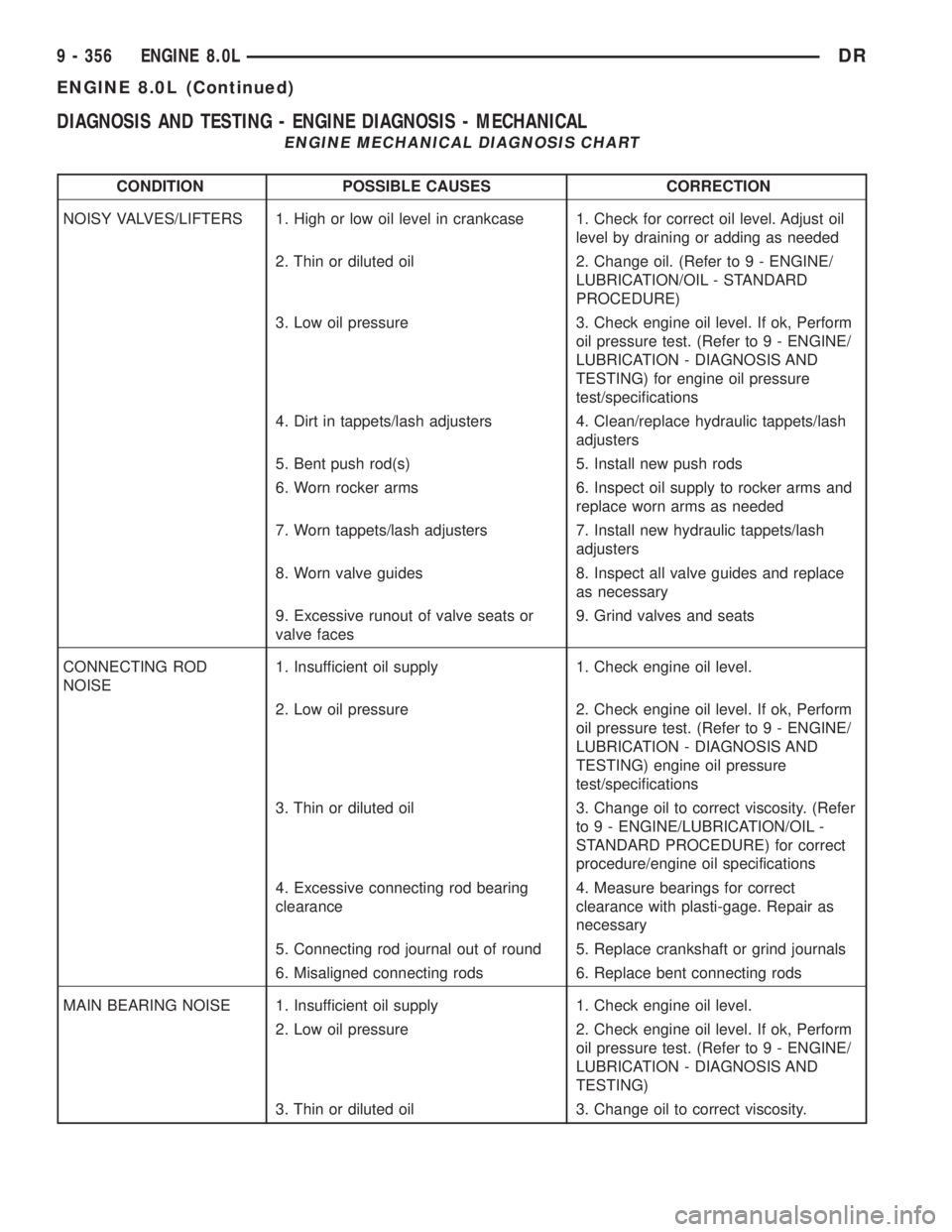
DIAGNOSIS AND TESTING - ENGINE DIAGNOSIS - MECHANICAL
ENGINE MECHANICAL DIAGNOSIS CHART
CONDITION POSSIBLE CAUSES CORRECTION
NOISY VALVES/LIFTERS 1. High or low oil level in crankcase 1. Check for correct oil level. Adjust oil
level by draining or adding as needed
2. Thin or diluted oil 2. Change oil. (Refer to 9 - ENGINE/
LUBRICATION/OIL - STANDARD
PROCEDURE)
3. Low oil pressure 3. Check engine oil level. If ok, Perform
oil pressure test. (Refer to 9 - ENGINE/
LUBRICATION - DIAGNOSIS AND
TESTING) for engine oil pressure
test/specifications
4. Dirt in tappets/lash adjusters 4. Clean/replace hydraulic tappets/lash
adjusters
5. Bent push rod(s) 5. Install new push rods
6. Worn rocker arms 6. Inspect oil supply to rocker arms and
replace worn arms as needed
7. Worn tappets/lash adjusters 7. Install new hydraulic tappets/lash
adjusters
8. Worn valve guides 8. Inspect all valve guides and replace
as necessary
9. Excessive runout of valve seats or
valve faces9. Grind valves and seats
CONNECTING ROD
NOISE1. Insufficient oil supply 1. Check engine oil level.
2. Low oil pressure 2. Check engine oil level. If ok, Perform
oil pressure test. (Refer to 9 - ENGINE/
LUBRICATION - DIAGNOSIS AND
TESTING) engine oil pressure
test/specifications
3. Thin or diluted oil 3. Change oil to correct viscosity. (Refer
to 9 - ENGINE/LUBRICATION/OIL -
STANDARD PROCEDURE) for correct
procedure/engine oil specifications
4. Excessive connecting rod bearing
clearance4. Measure bearings for correct
clearance with plasti-gage. Repair as
necessary
5. Connecting rod journal out of round 5. Replace crankshaft or grind journals
6. Misaligned connecting rods 6. Replace bent connecting rods
MAIN BEARING NOISE 1. Insufficient oil supply 1. Check engine oil level.
2. Low oil pressure 2. Check engine oil level. If ok, Perform
oil pressure test. (Refer to 9 - ENGINE/
LUBRICATION - DIAGNOSIS AND
TESTING)
3. Thin or diluted oil 3. Change oil to correct viscosity.
9 - 356 ENGINE 8.0LDR
ENGINE 8.0L (Continued)
Page 1624 of 2895
INTAKE/EXHAUST VALVES &
SEATS
DESCRIPTION
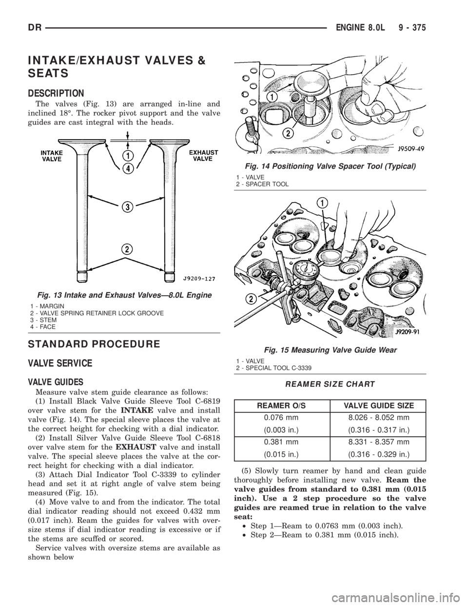
The valves (Fig. 13) are arranged in-line and
inclined 18É. The rocker pivot support and the valve
guides are cast integral with the heads.
STANDARD PROCEDURE
VALVE SERVICE
VALVE GUIDES
Measure valve stem guide clearance as follows:
(1) Install Black Valve Guide Sleeve Tool C-6819
over valve stem for theINTAKEvalve and install
valve (Fig. 14). The special sleeve places the valve at
the correct height for checking with a dial indicator.
(2) Install Silver Valve Guide Sleeve Tool C-6818
over valve stem for theEXHAUSTvalve and install
valve. The special sleeve places the valve at the cor-
rect height for checking with a dial indicator.
(3) Attach Dial Indicator Tool C-3339 to cylinder
head and set it at right angle of valve stem being
measured (Fig. 15).
(4) Move valve to and from the indicator. The total
dial indicator reading should not exceed 0.432 mm
(0.017 inch). Ream the guides for valves with over-
size stems if dial indicator reading is excessive or if
the stems are scuffed or scored.
Service valves with oversize stems are available as
shown below
REAMER SIZE CHART
REAMER O/S VALVE GUIDE SIZE
0.076 mm 8.026 - 8.052 mm
(0.003 in.) (0.316 - 0.317 in.)
0.381 mm 8.331 - 8.357 mm
(0.015 in.) (0.316 - 0.329 in.)
(5) Slowly turn reamer by hand and clean guide
thoroughly before installing new valve.Ream the
valve guides from standard to 0.381 mm (0.015
inch). Use a 2 step procedure so the valve
guides are reamed true in relation to the valve
seat:
²Step 1ÐReam to 0.0763 mm (0.003 inch).
²Step 2ÐReam to 0.381 mm (0.015 inch).
Fig. 13 Intake and Exhaust ValvesÐ8.0L Engine
1 - MARGIN
2 - VALVE SPRING RETAINER LOCK GROOVE
3 - STEM
4-FACE
Fig. 14 Positioning Valve Spacer Tool (Typical)
1 - VALVE
2 - SPACER TOOL
Fig. 15 Measuring Valve Guide Wear
1 - VALVE
2 - SPECIAL TOOL C-3339
DRENGINE 8.0L 9 - 375
Page 1625 of 2895
REFACING VALVES AND VALVE SEATS
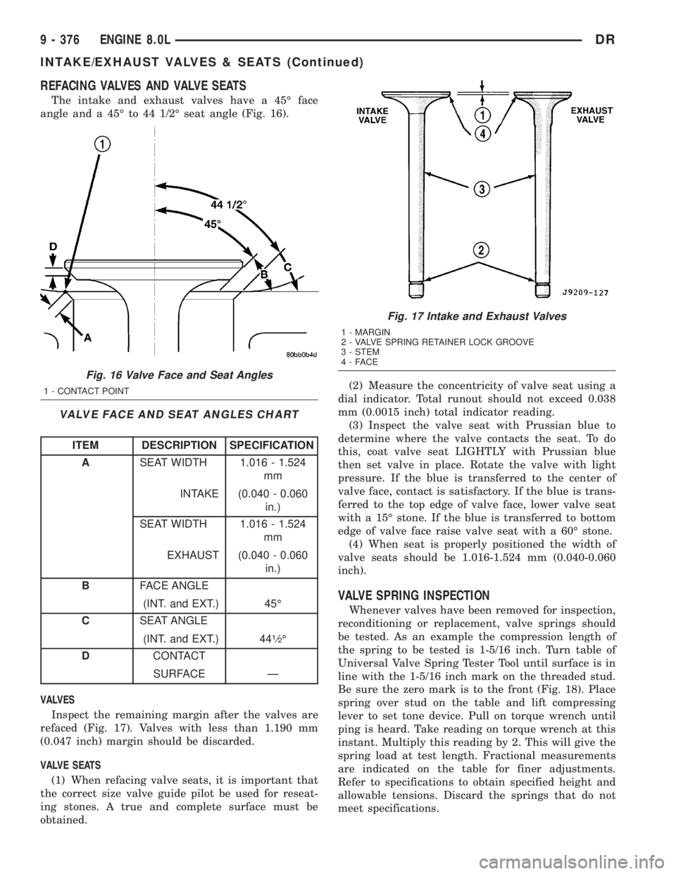
The intake and exhaust valves have a 45É face
angle and a 45É to 44 1/2É seat angle (Fig. 16).
VALVE FACE AND SEAT ANGLES CHART
ITEM DESCRIPTION SPECIFICATION
ASEAT WIDTH 1.016 - 1.524
mm
INTAKE (0.040 - 0.060
in.)
SEAT WIDTH 1.016 - 1.524
mm
EXHAUST (0.040 - 0.060
in.)
BFACE ANGLE
(INT. and EXT.) 45É
CSEAT ANGLE
(INT. and EXT.) 44
1¤2É
DCONTACT
SURFACE Ð
VALVES
Inspect the remaining margin after the valves are
refaced (Fig. 17). Valves with less than 1.190 mm
(0.047 inch) margin should be discarded.
VALVE SEATS
(1) When refacing valve seats, it is important that
the correct size valve guide pilot be used for reseat-
ing stones. A true and complete surface must be
obtained.(2) Measure the concentricity of valve seat using a
dial indicator. Total runout should not exceed 0.038
mm (0.0015 inch) total indicator reading.
(3) Inspect the valve seat with Prussian blue to
determine where the valve contacts the seat. To do
this, coat valve seat LIGHTLY with Prussian blue
then set valve in place. Rotate the valve with light
pressure. If the blue is transferred to the center of
valve face, contact is satisfactory. If the blue is trans-
ferred to the top edge of valve face, lower valve seat
with a 15É stone. If the blue is transferred to bottom
edge of valve face raise valve seat with a 60É stone.
(4) When seat is properly positioned the width of
valve seats should be 1.016-1.524 mm (0.040-0.060
inch).
VALVE SPRING INSPECTION
Whenever valves have been removed for inspection,
reconditioning or replacement, valve springs should
be tested. As an example the compression length of
the spring to be tested is 1-5/16 inch. Turn table of
Universal Valve Spring Tester Tool until surface is in
line with the 1-5/16 inch mark on the threaded stud.
Be sure the zero mark is to the front (Fig. 18). Place
spring over stud on the table and lift compressing
lever to set tone device. Pull on torque wrench until
ping is heard. Take reading on torque wrench at this
instant. Multiply this reading by 2. This will give the
spring load at test length. Fractional measurements
are indicated on the table for finer adjustments.
Refer to specifications to obtain specified height and
allowable tensions. Discard the springs that do not
meet specifications.
Fig. 16 Valve Face and Seat Angles
1 - CONTACT POINT
Fig. 17 Intake and Exhaust Valves
1 - MARGIN
2 - VALVE SPRING RETAINER LOCK GROOVE
3 - STEM
4-FACE
9 - 376 ENGINE 8.0LDR
INTAKE/EXHAUST VALVES & SEATS (Continued)
Page 1626 of 2895
REMOVAL
REMOVALÐVALVE STEM SEALS
NOTE: This procedure is done with the cylinder
head installed.
(1) Disconnect the negative cable from the battery.
(2) Set engine basic timing to Top Dead Center
(TDC) and remove air cleaner.
(3) Remove cylinder head covers (Refer to 9 -
ENGINE/CYLINDER HEAD/CYLINDER HEAD
COVER(S) - REMOVAL) and spark plugs (Refer to 8
- ELECTRICAL/IGNITION CONTROL/SPARK
PLUG - REMOVAL).
(4) Using suitable socket and flex handle at crank-
shaft retaining bolt, turn engine so that the piston of
the cylinder to be worked on, is at TDC on the com-
pression stroke.
(5) Remove rocker arms (Refer to 9 - ENGINE/
CYLINDER HEAD/ROCKER ARM / ADJUSTER
ASSY - REMOVAL).
(6) With air hose attached to an adapter installed
in the spark plug hole, apply 620-689 kPa (90-100
psi) air pressure.
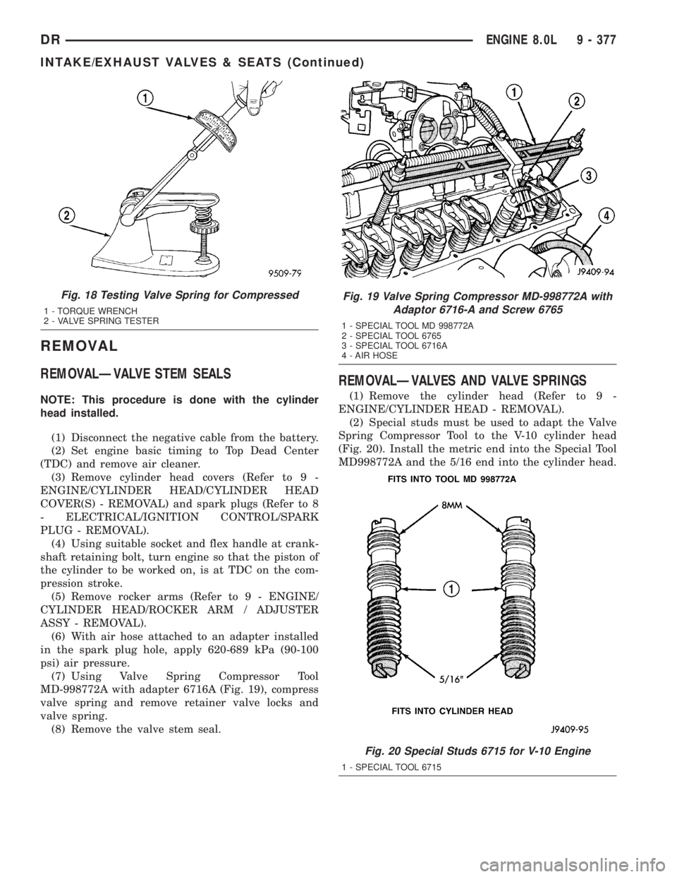
(7) Using Valve Spring Compressor Tool
MD-998772A with adapter 6716A (Fig. 19), compress
valve spring and remove retainer valve locks and
valve spring.
(8) Remove the valve stem seal.
REMOVALÐVALVES AND VALVE SPRINGS
(1) Remove the cylinder head (Refer to 9 -
ENGINE/CYLINDER HEAD - REMOVAL).
(2) Special studs must be used to adapt the Valve
Spring Compressor Tool to the V-10 cylinder head
(Fig. 20). Install the metric end into the Special Tool
MD998772A and the 5/16 end into the cylinder head.
Fig. 18 Testing Valve Spring for Compressed
1 - TORQUE WRENCH
2 - VALVE SPRING TESTER
Fig. 19 Valve Spring Compressor MD-998772A with
Adaptor 6716-A and Screw 6765
1 - SPECIAL TOOL MD 998772A
2 - SPECIAL TOOL 6765
3 - SPECIAL TOOL 6716A
4 - AIR HOSE
Fig. 20 Special Studs 6715 for V-10 Engine
1 - SPECIAL TOOL 6715
DRENGINE 8.0L 9 - 377
INTAKE/EXHAUST VALVES & SEATS (Continued)
Page 1627 of 2895
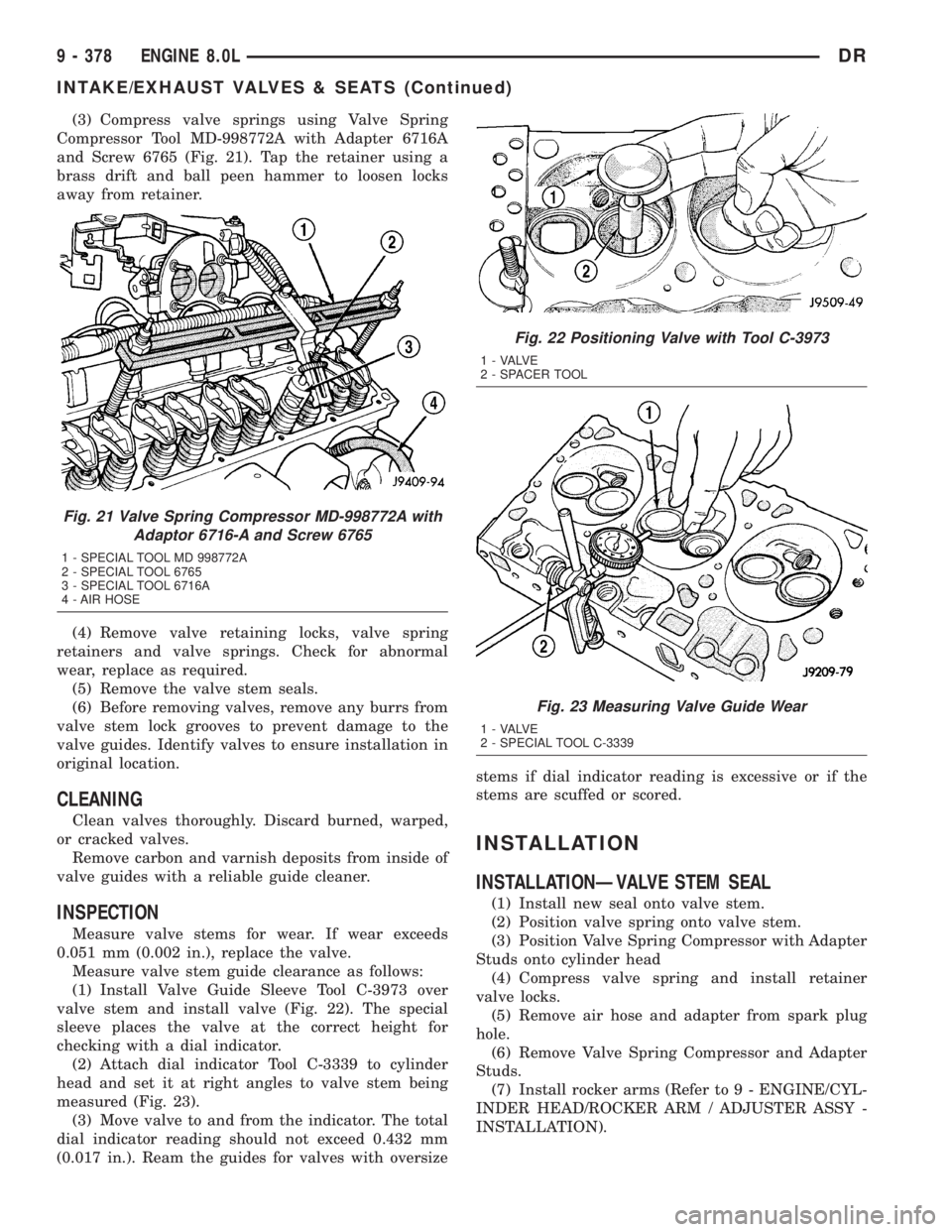
(3) Compress valve springs using Valve Spring
Compressor Tool MD-998772A with Adapter 6716A
and Screw 6765 (Fig. 21). Tap the retainer using a
brass drift and ball peen hammer to loosen locks
away from retainer.
(4) Remove valve retaining locks, valve spring
retainers and valve springs. Check for abnormal
wear, replace as required.
(5) Remove the valve stem seals.
(6) Before removing valves, remove any burrs from
valve stem lock grooves to prevent damage to the
valve guides. Identify valves to ensure installation in
original location.
CLEANING
Clean valves thoroughly. Discard burned, warped,
or cracked valves.
Remove carbon and varnish deposits from inside of
valve guides with a reliable guide cleaner.
INSPECTION
Measure valve stems for wear. If wear exceeds
0.051 mm (0.002 in.), replace the valve.
Measure valve stem guide clearance as follows:
(1) Install Valve Guide Sleeve Tool C-3973 over
valve stem and install valve (Fig. 22). The special
sleeve places the valve at the correct height for
checking with a dial indicator.
(2) Attach dial indicator Tool C-3339 to cylinder
head and set it at right angles to valve stem being
measured (Fig. 23).
(3) Move valve to and from the indicator. The total
dial indicator reading should not exceed 0.432 mm
(0.017 in.). Ream the guides for valves with oversizestems if dial indicator reading is excessive or if the
stems are scuffed or scored.
INSTALLATION
INSTALLATIONÐVALVE STEM SEAL
(1) Install new seal onto valve stem.
(2) Position valve spring onto valve stem.
(3) Position Valve Spring Compressor with Adapter
Studs onto cylinder head
(4) Compress valve spring and install retainer
valve locks.
(5) Remove air hose and adapter from spark plug
hole.
(6) Remove Valve Spring Compressor and Adapter
Studs.
(7) Install rocker arms (Refer to 9 - ENGINE/CYL-
INDER HEAD/ROCKER ARM / ADJUSTER ASSY -
INSTALLATION).
Fig. 21 Valve Spring Compressor MD-998772A with
Adaptor 6716-A and Screw 6765
1 - SPECIAL TOOL MD 998772A
2 - SPECIAL TOOL 6765
3 - SPECIAL TOOL 6716A
4 - AIR HOSE
Fig. 22 Positioning Valve with Tool C-3973
1 - VALVE
2 - SPACER TOOL
Fig. 23 Measuring Valve Guide Wear
1 - VALVE
2 - SPECIAL TOOL C-3339
9 - 378 ENGINE 8.0LDR
INTAKE/EXHAUST VALVES & SEATS (Continued)
Page 1628 of 2895
(8) The cylinder head cover gasket can be used
again. Install the gasket onto the head rail.For the
left side the number tab is at the front of
engine with the number up. For the right side
the number tab is at the rear of engine with the
number up.
CAUTION: The cylinder head cover fasteners have a
special plating. DO NOT use alternative fasteners.
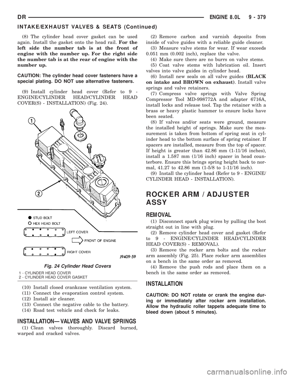
(9) Install cylinder head cover (Refer to 9 -
ENGINE/CYLINDER HEAD/CYLINDER HEAD
COVER(S) - INSTALLATION) (Fig. 24).
(10) Install closed crankcase ventilation system.
(11) Connect the evaporation control system.
(12) Install air cleaner.
(13) Connect the negative cable to the battery.
(14) Road test vehicle and check for leaks.
INSTALLATIONÐVALVES AND VALVE SPRINGS
(1) Clean valves thoroughly. Discard burned,
warped and cracked valves.(2) Remove carbon and varnish deposits from
inside of valve guides with a reliable guide cleaner.
(3) Measure valve stems for wear. If wear exceeds
0.051 mm (0.002 inch), replace the valve.
(4) Make sure there are no burrs on valve stems.
(5) Coat valve stems with lubrication oil. Insert
valves into valve guides in cylinder head.
(6) Install new seals on all valve guides(BLACK
on intake and BROWN on exhaust). Install valve
springs and valve retainers.
(7) Compress valve springs with Valve Spring
Compressor Tool MD-998772A and adapter 6716A,
install locks and release tool. Tap the retainer with a
brass or heavy plastic hammer to ensure locks have
been seated.
(8) If valves and/or seats were ground, measure
the installed height of springs. Make sure the mea-
surement is taken from bottom of spring seat in cyl-
inder head to the bottom surface of spring retainer. If
spacers are installed, measure from the top of spacer.
If height is greater than 42.86 mm (1-11/16 inches),
install a 1.587 mm (1/16 inch) spacer in head coun-
terbore. Ensure this brings spring height back to nor-
mal, 41.27 to 42.86 mm (1-5/8 to 1-11/16 inch).
(9) Install the cylinder head (Refer to 9 - ENGINE/
CYLINDER HEAD - INSTALLATION).
ROCKER ARM / ADJUSTER
ASSY
REMOVAL
(1) Disconnect spark plug wires by pulling the boot
straight out in line with plug.
(2) Remove cylinder head cover and gasket (Refer
to 9 - ENGINE/CYLINDER HEAD/CYLINDER
HEAD COVER(S) - REMOVAL).
(3) Remove the rocker arm bolts and the rocker
arm assembly (Fig. 25). Place rocker arm assemblies
on a bench in the same order as removed.
(4) Remove the push rods and place them on a
bench in the same order as removed.
INSTALLATION
CAUTION: DO NOT rotate or crank the engine dur-
ing or immediately after rocker arm installation.
Allow the hydraulic roller tappets adequate time to
bleed down (about 5 minutes).
Fig. 24 Cylinder Head Covers
1 - CYLINDER HEAD COVER
2 - CYLINDER HEAD COVER GASKET
DRENGINE 8.0L 9 - 379
INTAKE/EXHAUST VALVES & SEATS (Continued)
Page 1630 of 2895
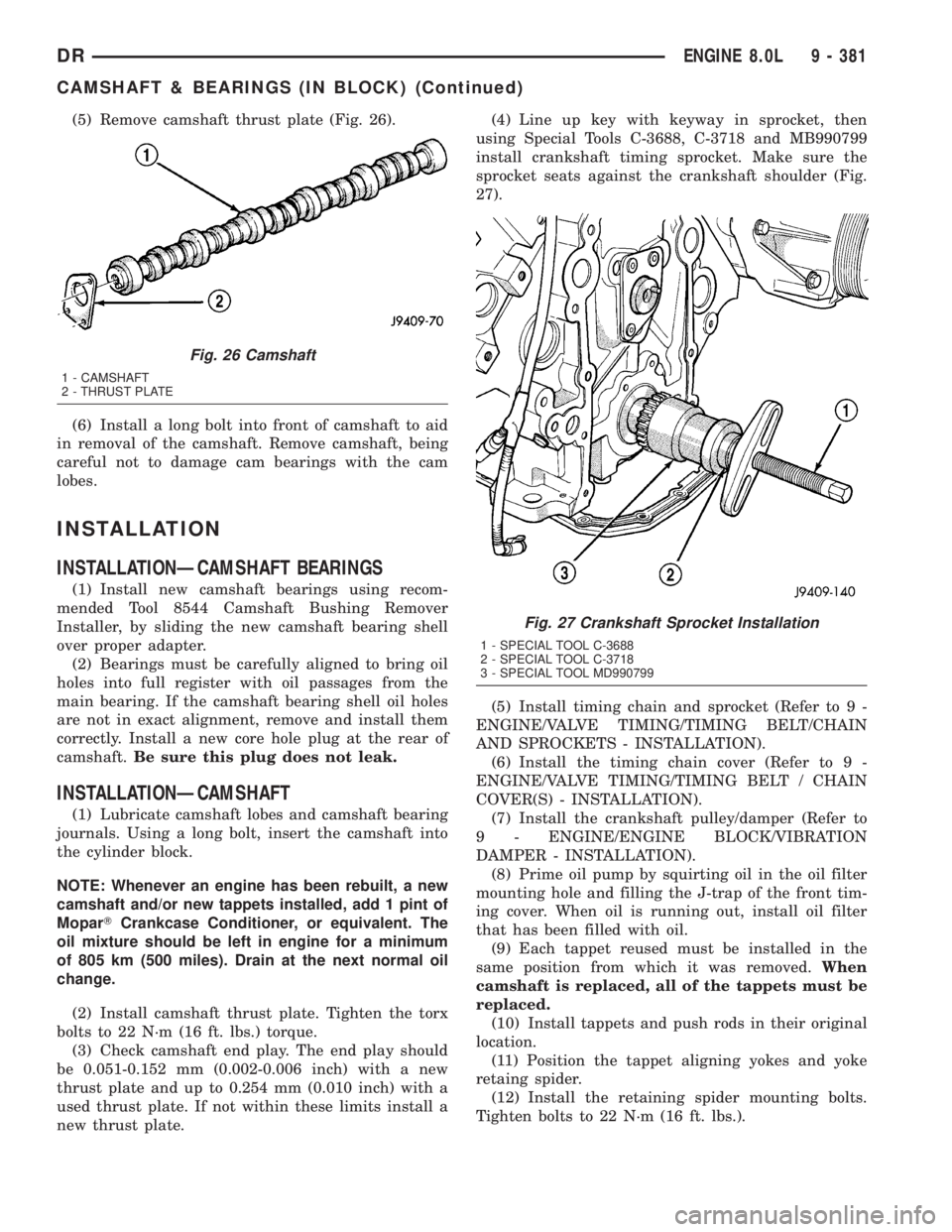
(5) Remove camshaft thrust plate (Fig. 26).
(6) Install a long bolt into front of camshaft to aid
in removal of the camshaft. Remove camshaft, being
careful not to damage cam bearings with the cam
lobes.
INSTALLATION
INSTALLATIONÐCAMSHAFT BEARINGS
(1) Install new camshaft bearings using recom-
mended Tool 8544 Camshaft Bushing Remover
Installer, by sliding the new camshaft bearing shell
over proper adapter.
(2) Bearings must be carefully aligned to bring oil
holes into full register with oil passages from the
main bearing. If the camshaft bearing shell oil holes
are not in exact alignment, remove and install them
correctly. Install a new core hole plug at the rear of
camshaft.Be sure this plug does not leak.
INSTALLATIONÐCAMSHAFT
(1) Lubricate camshaft lobes and camshaft bearing
journals. Using a long bolt, insert the camshaft into
the cylinder block.
NOTE: Whenever an engine has been rebuilt, a new
camshaft and/or new tappets installed, add 1 pint of
MoparTCrankcase Conditioner, or equivalent. The
oil mixture should be left in engine for a minimum
of 805 km (500 miles). Drain at the next normal oil
change.
(2) Install camshaft thrust plate. Tighten the torx
bolts to 22 N´m (16 ft. lbs.) torque.
(3) Check camshaft end play. The end play should
be 0.051-0.152 mm (0.002-0.006 inch) with a new
thrust plate and up to 0.254 mm (0.010 inch) with a
used thrust plate. If not within these limits install a
new thrust plate.(4) Line up key with keyway in sprocket, then
using Special Tools C-3688, C-3718 and MB990799
install crankshaft timing sprocket. Make sure the
sprocket seats against the crankshaft shoulder (Fig.
27).
(5) Install timing chain and sprocket (Refer to 9 -
ENGINE/VALVE TIMING/TIMING BELT/CHAIN
AND SPROCKETS - INSTALLATION).
(6) Install the timing chain cover (Refer to 9 -
ENGINE/VALVE TIMING/TIMING BELT / CHAIN
COVER(S) - INSTALLATION).
(7) Install the crankshaft pulley/damper (Refer to
9 - ENGINE/ENGINE BLOCK/VIBRATION
DAMPER - INSTALLATION).
(8) Prime oil pump by squirting oil in the oil filter
mounting hole and filling the J-trap of the front tim-
ing cover. When oil is running out, install oil filter
that has been filled with oil.
(9) Each tappet reused must be installed in the
same position from which it was removed.When
camshaft is replaced, all of the tappets must be
replaced.
(10) Install tappets and push rods in their original
location.
(11) Position the tappet aligning yokes and yoke
retaing spider.
(12) Install the retaining spider mounting bolts.
Tighten bolts to 22 N´m (16 ft. lbs.).
Fig. 26 Camshaft
1 - CAMSHAFT
2 - THRUST PLATE
Fig. 27 Crankshaft Sprocket Installation
1 - SPECIAL TOOL C-3688
2 - SPECIAL TOOL C-3718
3 - SPECIAL TOOL MD990799
DRENGINE 8.0L 9 - 381
CAMSHAFT & BEARINGS (IN BLOCK) (Continued)