2003 DODGE RAM seats
[x] Cancel search: seatsPage 2658 of 2895
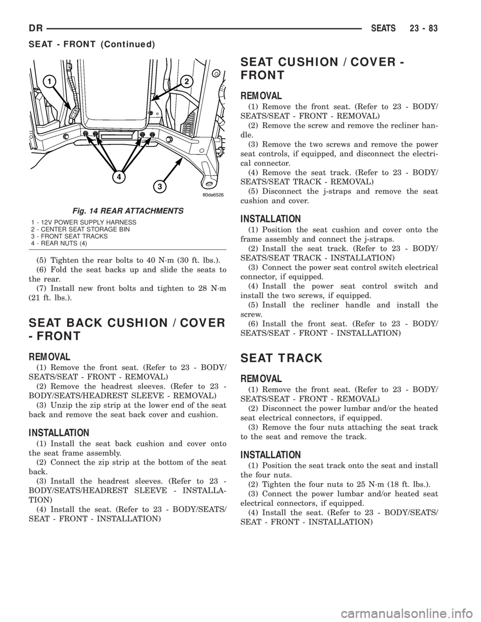
(5) Tighten the rear bolts to 40 N´m (30 ft. lbs.).
(6) Fold the seat backs up and slide the seats to
the rear.
(7) Install new front bolts and tighten to 28 N´m
(21 ft. lbs.).
SEAT BACK CUSHION / COVER
- FRONT
REMOVAL
(1) Remove the front seat. (Refer to 23 - BODY/
SEATS/SEAT - FRONT - REMOVAL)
(2) Remove the headrest sleeves. (Refer to 23 -
BODY/SEATS/HEADREST SLEEVE - REMOVAL)
(3) Unzip the zip strip at the lower end of the seat
back and remove the seat back cover and cushion.
INSTALLATION
(1) Install the seat back cushion and cover onto
the seat frame assembly.
(2) Connect the zip strip at the bottom of the seat
back.
(3) Install the headrest sleeves. (Refer to 23 -
BODY/SEATS/HEADREST SLEEVE - INSTALLA-
TION)
(4) Install the seat. (Refer to 23 - BODY/SEATS/
SEAT - FRONT - INSTALLATION)
SEAT CUSHION / COVER -
FRONT
REMOVAL
(1) Remove the front seat. (Refer to 23 - BODY/
SEATS/SEAT - FRONT - REMOVAL)
(2) Remove the screw and remove the recliner han-
dle.
(3) Remove the two screws and remove the power
seat controls, if equipped, and disconnect the electri-
cal connector.
(4) Remove the seat track. (Refer to 23 - BODY/
SEATS/SEAT TRACK - REMOVAL)
(5) Disconnect the j-straps and remove the seat
cushion and cover.
INSTALLATION
(1) Position the seat cushion and cover onto the
frame assembly and connect the j-straps.
(2) Install the seat track. (Refer to 23 - BODY/
SEATS/SEAT TRACK - INSTALLATION)
(3) Connect the power seat control switch electrical
connector, if equipped.
(4) Install the power seat control switch and
install the two screws, if equipped.
(5) Install the recliner handle and install the
screw.
(6) Install the front seat. (Refer to 23 - BODY/
SEATS/SEAT - FRONT - INSTALLATION)
SEAT TRACK
REMOVAL
(1) Remove the front seat. (Refer to 23 - BODY/
SEATS/SEAT - FRONT - REMOVAL)
(2) Disconnect the power lumbar and/or the heated
seat electrical connectors, if equipped.
(3) Remove the four nuts attaching the seat track
to the seat and remove the track.
INSTALLATION
(1) Position the seat track onto the seat and install
the four nuts.
(2) Tighten the four nuts to 25 N´m (18 ft. lbs.).
(3) Connect the power lumbar and/or heated seat
electrical connectors, if equipped.
(4) Install the seat. (Refer to 23 - BODY/SEATS/
SEAT - FRONT - INSTALLATION)
Fig. 14 REAR ATTACHMENTS
1 - 12V POWER SUPPLY HARNESS
2 - CENTER SEAT STORAGE BIN
3 - FRONT SEAT TRACKS
4 - REAR NUTS (4)
DRSEATS 23 - 83
SEAT - FRONT (Continued)
Page 2659 of 2895
SEAT - REAR
REMOVAL
(1) Remove the load floor. (Refer to 23 - BODY/IN-
TERIOR/LOAD FLOOR - REMOVAL)
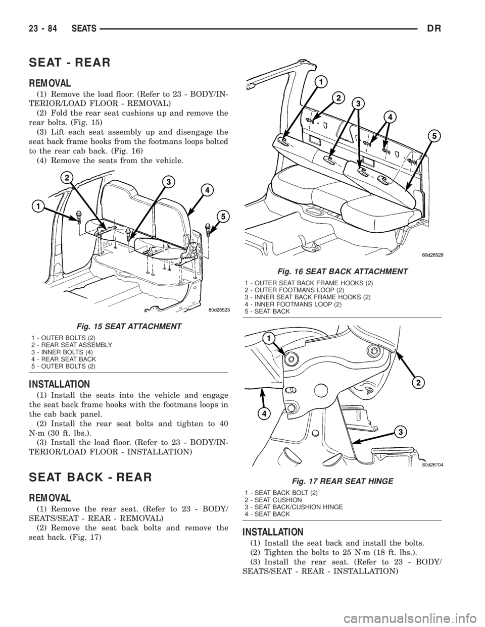
(2) Fold the rear seat cushions up and remove the
rear bolts. (Fig. 15)
(3) Lift each seat assembly up and disengage the
seat back frame hooks from the footmans loops bolted
to the rear cab back. (Fig. 16)
(4) Remove the seats from the vehicle.
INSTALLATION
(1) Install the seats into the vehicle and engage
the seat back frame hooks with the footmans loops in
the cab back panel.
(2) Install the rear seat bolts and tighten to 40
N´m (30 ft. lbs.).
(3) Install the load floor. (Refer to 23 - BODY/IN-
TERIOR/LOAD FLOOR - INSTALLATION)
SEAT BACK - REAR
REMOVAL
(1) Remove the rear seat. (Refer to 23 - BODY/
SEATS/SEAT - REAR - REMOVAL)
(2) Remove the seat back bolts and remove the
seat back. (Fig. 17)
INSTALLATION
(1) Install the seat back and install the bolts.
(2) Tighten the bolts to 25 N´m (18 ft. lbs.).
(3) Install the rear seat. (Refer to 23 - BODY/
SEATS/SEAT - REAR - INSTALLATION)
Fig. 15 SEAT ATTACHMENT
1 - OUTER BOLTS (2)
2 - REAR SEAT ASSEMBLY
3 - INNER BOLTS (4)
4 - REAR SEAT BACK
5 - OUTER BOLTS (2)
Fig. 16 SEAT BACK ATTACHMENT
1 - OUTER SEAT BACK FRAME HOOKS (2)
2 - OUTER FOOTMANS LOOP (2)
3 - INNER SEAT BACK FRAME HOOKS (2)
4 - INNER FOOTMANS LOOP (2)
5 - SEAT BACK
Fig. 17 REAR SEAT HINGE
1 - SEAT BACK BOLT (2)
2 - SEAT CUSHION
3 - SEAT BACK/CUSHION HINGE
4 - SEAT BACK
23 - 84 SEATSDR
Page 2660 of 2895
SEAT BACK CUSHION / COVER
- REAR
REMOVAL
(1) Remove the rear seat back. (Refer to 23 -
BODY/SEATS/SEAT BACK - REAR - REMOVAL)
(2) Unzip the zip strip at the bottom of the seat
back and remove the cover and cushion.
INSTALLATION
(1) Install the seat back cushion and cover and
connect the zip strip.
(2) Install the seat back. (Refer to 23 - BODY/
SEATS/SEAT BACK - REAR - INSTALLATION)
SEAT CUSHION / COVER -
REAR
REMOVAL
(1) Remove the rear seat. (Refer to 23 - BODY/
SEATS/SEAT - REAR - REMOVAL)
(2) Remove the screws and remove the grocery bag
hooks, if equipped.
(3) Separate the zip strip at the rear of the seat
cushion and remove the cushion and cover.
INSTALLATION
(1) Install the seat cushion and cover over the
cushion frame assembly and connect the zip strip.
(2) Install the grocery bag hooks and screws, if
equipped.
(3) Install the seat. (Refer to 23 - BODY/SEATS/
SEAT - REAR - INSTALLATION)
SEAT CUSHION FRAME - REAR
REMOVAL
(1) Remove the seat cushion/cover. (Refer to 23 -
BODY/SEATS/SEAT CUSHION / COVER - REAR -
REMOVAL)
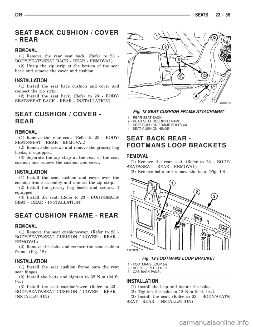
(2) Remove the bolts and remove the seat cushion
frame. (Fig. 18)
INSTALLATION
(1) Install the seat cushion frame onto the rear
seat hinges.
(2) Install the bolts and tighten to 32 N´m (24 ft.
lbs.).
(3) Install the seat cushion/cover. (Refer to 23 -
BODY/SEATS/SEAT CUSHION / COVER - REAR -
INSTALLATION)
SEAT BACK REAR -
FOOTMANS LOOP BRACKETS
REMOVAL
(1) Remove the rear seat. (Refer to 23 - BODY/
SEATS/SEAT - REAR - REMOVAL)
(2) Remove bolts and remove the loop. (Fig. 19)
INSTALLATION
(1) Install the loop and install the bolts.
(2) Tighten the bolts to 12 N´m (9 ft. lbs.).
(3) Install the seat. (Refer to 23 - BODY/SEATS/
SEAT - REAR - INSTALLATION)
Fig. 18 SEAT CUSHION FRAME ATTACHMENT
1 - REAR SEAT BACK
2 - REAR SEAT CUSHION FRAME
3 - SEAT CUSHION FRAME BOLTS (4)
4 - SEAT CUSHION HINGE
Fig. 19 FOOTMANS LOOP BRACKET
1 - FOOTMANS LOOP (4)
2 - BOLTS (2 PER LOOP)
3 - CAB BACK PANEL
DRSEATS 23 - 85
Page 2811 of 2895
nents, caused by condenser air flow restriction or an
overcharge of refrigerant.
OPERATION
OPERATION
The compressor is driven by the engine through an
electric clutch, drive rotor and belt arrangement. The
compressor is lubricated by refrigerant oil that is cir-
culated throughout the refrigerant system with the
refrigerant.
The compressor draws in low-pressure refrigerant
vapor from the evaporator through its suction port. It
then compresses the refrigerant into a high-pressure,
high-temperature refrigerant vapor, which is then
pumped to the condenser through the compressor dis-
charge port.
The compressor cannot be repaired. If faulty or
damaged, the entire compressor assembly must be
replaced. The compressor clutch, pulley and clutch
coil are available for service.
OPERATION - HIGH PRESSURE RELIEF VALVE
The high pressure relief valve vents the system
when a discharge pressure of 3445 to 4135 kPa (500
to 600 psi) or above is reached. The valve closes
when a minimum discharge pressure of 2756 kPa
(400 psi) is reached.
The high pressure relief valve vents only enough
refrigerant to reduce the system pressure, and then
re-seats itself. The majority of the refrigerant is con-
served in the system. If the valve vents refrigerant, it
does not mean that the valve is faulty.
The high pressure relief valve is a factory-cali-
brated unit. The valve cannot be adjusted or
repaired, and must not be removed or otherwise dis-
turbed. The valve is only serviced as a part of the
compressor assembly.
DIAGNOSIS AND TESTING - A/C COMPRESSOR
NOISE
When investigating an air conditioning related
noise, you must first know the conditions under
which the noise occurs. These conditions include:
weather, vehicle speed, transmission in gear or neu-
tral, engine speed, engine temperature, and any
other special conditions. Noises that develop during
air conditioning operation can often be misleading.
For example: What sounds like a failed front bearing
or connecting rod, may be caused by loose bolts, nuts,
mounting brackets, or a loose compressor clutch
assembly.
Drive belts are speed sensitive. At different engine
speeds and depending upon belt tension, belts can
develop noises that are mistaken for a compressornoise. Improper belt tension can cause a misleading
noise when the compressor clutch is engaged, which
may not occur when the compressor clutch is disen-
gaged. Check the serpentine drive belt condition and
tension as described in Cooling before beginning this
procedure.
(1) Select a quiet area for testing. Duplicate the
complaint conditions as much as possible. Switch the
compressor on and off several times to clearly iden-
tify the compressor noise. Listen to the compressor
while the clutch is engaged and disengaged. Probe
the compressor with an engine stethoscope or a long
screwdriver with the handle held to your ear to bet-
ter localize the source of the noise.
(2) Loosen all of the compressor mounting hard-
ware and retighten. Tighten the compressor clutch
mounting nut. Be certain that the clutch coil is
mounted securely to the compressor, and that the
clutch plate and rotor are properly aligned and have
the correct air gap. (Refer to 24 - HEATING & AIR
CONDITIONING/CONTROLS/A/C COMPRESSOR
CLUTCH - INSTALLATION)
(3) To duplicate a high-ambient temperature condi-
tion (high head pressure), restrict the air flow
through the condenser. Install a manifold gauge set
to be certain that the discharge pressure does not
exceed 2760 kPa (400 psi).
(4) Check the refrigerant system plumbing for
incorrect routing, rubbing or interference, which can
cause unusual noises. Also check the refrigerant lines
for kinks or sharp bends that will restrict refrigerant
flow, which can cause noises. (Refer to 24 - HEAT-
ING & AIR CONDITIONING/PLUMBING - CAU-
TION)
(5) If the noise is from opening and closing of the
high pressure relief valve, evacuate and recharge the
refrigerant system. (Refer to 24 - HEATING & AIR
CONDITIONING/PLUMBING - STANDARD PRO-
CEDURE - REFRIGERANT SYSTEM EVACUATE)
(Refer to 24 - HEATING & AIR CONDITIONING/
PLUMBING - STANDARD PROCEDURE - REFRIG-
ERANT SYSTEM CHARGE) If the high pressure
relief valve still does not seat properly, replace the
compressor.
(6) If the noise is from liquid slugging on the suc-
tion line. Check the refrigerant oil level and the
refrigerant system charge. (Refer to 24 - HEATING
& AIR CONDITIONING/PLUMBING/REFRIGER-
ANT OIL - STANDARD PROCEDURE) (Refer to 24 -
HEATING & AIR CONDITIONING/PLUMBING -
SPECIFICATIONS - CHARGE CAPACITY) If either
is out of specification range reclaim, evacuate and
recharge the refrigerent system(Refer to 24 - HEAT-
ING & AIR CONDITIONING/PLUMBING/REFRIG-
ERANT - STANDARD PROCEDURE), (Refer to 24 -
HEATING & AIR CONDITIONING/PLUMBING/RE-
24 - 36 PLUMBINGDR
A/C COMPRESSOR (Continued)
Page 2873 of 2895
INDICATOR - DESCRIPTION, UPSHIFT....8J-40
INDICATOR - DESCRIPTION, WAIT-TO-
START .............................8J-42
INDICATOR - DESCRIPTION, WASHER
FLUID..............................8J-42
INDICATOR - DESCRIPTION, WATER-IN-
FUEL..............................8J-43
INDICATOR - DIAGNOSIS AND TESTING,
BRAKE.............................8J-19
INDICATOR - OPERATION, ABS..........8J-17
INDICATOR - OPERATION, AIRBAG.......8J-18
INDICATOR - OPERATION, BRAKE/PARK
BRAKE.............................8J-19
INDICATOR - OPERATION, CARGO LAMP . . 8J-20
INDICATOR - OPERATION, CHECK
GAUGES............................8J-21
INDICATOR - OPERATION, CRUISE.......8J-22
INDICATOR - OPERATION, DOOR AJAR . . . 8J-23
INDICATOR - OPERATION, ETC..........8J-25
INDICATOR - OPERATION, GEAR
SELECTOR..........................8J-27
INDICATOR - OPERATION, HIGH BEAM....8J-28
INDICATOR - OPERATION, LAMP OUT....8J-28
INDICATOR - OPERATION, LOW FUEL.....8J-29
INDICATOR - OPERATION, OVERDRIVE
OFF ...............................8J-33
INDICATOR - OPERATION, SEATBELT.....8J-34
INDICATOR - OPERATION, SECURITY.....8J-35
INDICATOR - OPERATION, SERVICE 4WD . . 8J-36
INDICATOR - OPERATION, TRANS TEMP . . 8J-38
INDICATOR - OPERATION, TURN SIGNAL . . 8J-39
INDICATOR - OPERATION, UPSHIFT......8J-40
INDICATOR - OPERATION, WAIT-TO-
START .............................8J-42
INDICATOR - OPERATION, WASHER
FLUID..............................8J-42
INDICATOR - OPERATION, WATER-IN-
FUEL..............................8J-43
INDICATOR LAMP - DESCRIPTION,
SENTRY KEY IMMOBILIZER SYSTEM......8Q-5
INDICATOR LAMP - OPERATION,
SENTRY KEY IMMOBILIZER SYSTEM......8Q-5
INDICATOR LAMP (MIL) - DESCRIPTION,
MALFUNCTION.......................8J-30
INDICATOR LAMP (MIL) - OPERATION,
MALFUNCTION.......................8J-30
INDICATOR TEST - STANDARD
PROCEDURE, BUILT-IN................8F-10
INDICATORS - DIAGNOSIS AND
TESTING, TREAD WEAR................22-7
INERTIA HINGE COVER - INSTALLATION,
CENTER SEAT BACK..................23-78
INERTIA HINGE COVER - REMOVAL,
CENTER SEAT BACK..................23-78
INFLATION PRESSURES - DESCRIPTION,
TIRE................................22-6
INFO CENTER - DESCRIPTION,
ELECTRONIC VEHICLE.................8M-7
INFO CENTER - INSTALLATION,
ELECTRONIC VEHICLE................8M-10
INFO CENTER - OPERATION,
ELECTRONIC VEHICLE.................8M-8
INFO CENTER - REMOVAL, ELECTRONIC
VEHICLE...........................8M-10
INITIAL OPERATION - STANDARD
PROCEDURE, POWER STEERING
PUMP.............................19-39
INITIALIZATION, STANDARD PROCEDURE
- SENTRY KEY IMMOBILIZER SYSTEM....8Q-3
INJECTION PUMP - DESCRIPTION, FUEL . . 14-64
INJECTION PUMP - INSTALLATION, FUEL . 14-67
INJECTION PUMP - OPERATION, FUEL
....14-64
INJECTION PUMP - REMOVAL, FUEL
.....14-65
INJECTION PUMP TIMING - DIAGNOSIS
AND TESTING, FUEL
..................14-65
INJECTOR - DESCRIPTION, FUEL
. . . 14-32,14-85
INJECTOR - INSTALLATION, FUEL
........14-87
INJECTOR - OPERATION, FUEL
.....14-32,14-86
INJECTOR - REMOVAL, FUEL
...........14-87
INJECTOR FIRING ORDER, DIESEL -
FUEL
..............................14-60
INJECTOR RAIL - DESCRIPTION, FUEL
....14-89
INJECTOR RAIL - INSTALLATION, FUEL
. . . 14-90
INJECTOR RAIL - OPERATION, FUEL
.....14-89
INJECTOR RAIL - REMOVAL, FUEL
.......14-89
INLET AIR TEMPERATURE SENSOR/
PRESSURE SENSOR - DESCRIPTION
.....14-90INLET AIR TEMPERATURE SENSOR/
PRESSURE SENSOR - INSTALLATION.....14-90
INLET AIR TEMPERATURE SENSOR/
PRESSURE SENSOR - OPERATION.......14-90
INLET AIR TEMPERATURE SENSOR/
PRESSURE SENSOR - REMOVAL........14-90
INLET FILTER - INSTALLATION..........14-23
INLET FILTER - REMOVAL..............14-23
INNER BELT MOLDING - INSTALLATION,
FRONT DOOR.......................23-93
INNER BELT MOLDING - INSTALLATION,
REAR DOOR........................23-94
INNER BELT MOLDING - REMOVAL,
FRONT DOOR.......................23-93
INNER BELT MOLDING - REMOVAL,
REAR DOOR........................23-94
INPUT - OPERATION, ASD SENSE - PCM . . . 8I-6
INPUT CLUTCH ASSEMBLY - ASSEMBLY . 21-552
INPUT CLUTCH ASSEMBLY -
DESCRIPTION......................21-549
INPUT CLUTCH ASSEMBLY -
DISASSEMBLY......................21-550
INPUT CLUTCH ASSEMBLY - OPERATION . 21-549
INPUT SHAFT SEAL - INSTALLATION,
STEERING GEAR.....................19-28
INPUT SHAFT SEAL - REMOVAL,
STEERING GEAR.....................19-25
INPUT SPEED SENSOR - DESCRIPTION . . 21-558
INPUT SPEED SENSOR - INSTALLATION . 21-559
INPUT SPEED SENSOR - OPERATION....21-558
INPUT SPEED SENSOR - REMOVAL.......21-559
INSERTS - INSTALLATION, SPRING TIP....2-42
INSERTS - REMOVAL, SPRING TIP........2-41
INSIDE HANDLE ACTUATOR -
INSTALLATION..................23-22,23-32
INSIDE HANDLE ACTUATOR - REMOVAL . . 23-22,
23-31
INSTALLED - INSTALLATION, FRONT OIL
SEAL - FRONT COVER.................9-384
INSTALLED - REMOVAL, FRONT OIL
SEAL - FRONT COVER.................9-384
INSTRUMENT CLUSTER - ASSEMBLY.....8J-15
INSTRUMENT CLUSTER - DESCRIPTION . . . 8J-2
INSTRUMENT CLUSTER - DIAGNOSIS
AND TESTING.......................8J-10
INSTRUMENT CLUSTER - DISASSEMBLY . . 8J-14
INSTRUMENT CLUSTER - INSTALLATION . . 8J-16
INSTRUMENT CLUSTER - OPERATION.....8J-6
INSTRUMENT CLUSTER - REMOVAL.....8J-14
INSTRUMENT PANEL ANTENNA CABLE -
INSTALLATION.......................8A-7
INSTRUMENT PANEL ANTENNA CABLE -
REMOVAL...........................8A-6
INSTRUMENT PANEL ASSEMBLY -
INSTALLATION.......................23-56
INSTRUMENT PANEL ASSEMBLY -
REMOVAL..........................23-53
INSTRUMENT PANEL CENTER BEZEL -
INSTALLATION.......................23-58
INSTRUMENT PANEL CENTER BEZEL -
REMOVAL..........................23-58
INSTRUMENT PANEL DRIVER SIDE
BEZEL - INSTALLATION................23-59
INSTRUMENT PANEL DRIVER SIDE
BEZEL - REMOVAL...................23-58
INSTRUMENT PANEL DUCTS -
INSTALLATION.......................24-29
INSTRUMENT PANEL DUCTS - REMOVAL . 24-29
INSTRUMENT PANEL HEADLAMP
SWITCH BEZEL - INSTALLATION.........23-57
INSTRUMENT PANEL HEADLAMP
SWITCH BEZEL - REMOVAL............23-57
INSTRUMENT PANEL LOWER
SURROUND - INSTALLATION...........23-60
INSTRUMENT PANEL LOWER
SURROUND - REMOVAL...............23-60
INSTRUMENT PANEL TOP COVER -
INSTALLATION.......................23-60
INSTRUMENT PANEL TOP COVER -
REMOVAL..........................23-59
INTAKE AIR HEATER - DESCRIPTION.....14-91
INTAKE AIR HEATER - INSTALLATION
.....14-91
INTAKE AIR HEATER - OPERATION
.......14-91
INTAKE AIR HEATER - REMOVAL
........14-91
INTAKE AIR HEATER RELAY -
DESCRIPTION
.......................14-92
INTAKE AIR HEATER RELAY -
INSTALLATION
.......................14-93INTAKE AIR HEATER RELAY -
OPERATION.........................14-92
INTAKE AIR HEATER RELAY - REMOVAL . . 14-93
INTAKE AIR TEMPERATURE SENSOR -
DESCRIPTION.......................14-36
INTAKE AIR TEMPERATURE SENSOR -
INSTALLATION.......................14-38
INTAKE AIR TEMPERATURE SENSOR -
OPERATION.........................14-36
INTAKE AIR TEMPERATURE SENSOR -
REMOVAL..........................14-36
INTAKE AIR TEMPERATURE SENSOR/
MAP SENSOR - DESCRIPTION..........14-93
INTAKE AIR TEMPERATURE SENSOR/
MAP SENSOR - INSTALLATION..........14-94
INTAKE AIR TEMPERATURE SENSOR/
MAP SENSOR - OPERATION............14-93
INTAKE AIR TEMPERATURE SENSOR/
MAP SENSOR - REMOVAL.............14-93
INTAKE MANIFOLD - CLEANING....9-158,9-219,
9-275,9-346,9-402
INTAKE MANIFOLD - DESCRIPTION . 9-157,9-219,
9-274,9-401,9-71
INTAKE MANIFOLD - INSPECTION . . 9-158,9-219,
9-275,9-346,9-402
INTAKE MANIFOLD - INSTALLATION.....9-158,
9-219,9-275,9-346,9-402,9-72
INTAKE MANIFOLD - OPERATION........9-274
INTAKE MANIFOLD - REMOVAL....9-157,9-219,
9-275,9-345,9-401,9-72
INTAKE MANIFOLD LEAKAGE -
DIAGNOSIS AND TESTING . . . 9-157,9-219,9-274,
9-401
INTAKE MANIFOLD LEAKS - DIAGNOSIS
AND TESTING........................9-71
INTAKE SYSTEM - INSTALLATION, AIR....9-194
INTAKE SYSTEM - REMOVAL, AIR.......9-194
INTAKE/EXHAUST VALVES & SEATS -
CLEANING..........................9-248
INTAKE/EXHAUST VALVES & SEATS -
DESCRIPTION....9-122,9-246,9-27,9-305,9-375
INTAKE/EXHAUST VALVES & SEATS -
INSPECTION........................9-248
INTAKE/EXHAUST VALVES & SEATS -
INSTALLATION..............9-123,9-248,9-29
INTAKE/EXHAUST VALVES & SEATS -
REMOVAL.................9-122,9-248,9-28
INTEGRATED POWER MODULE -
DESCRIPTION.....................8W-97-3
INTEGRATED POWER MODULE -
INSTALLATION....................8W-97-4
INTEGRATED POWER MODULE -
OPERATION.......................8W-97-3
INTEGRATED POWER MODULE -
REMOVAL........................8W-97-3
INTERIOR - CAUTION.................23-63
INTERLOCK - ADJUSTMENTS, BRAKE
TRANSMISSION SHIFT . . . 21-195,21-376,21-540
INTERLOCK - DIAGNOSIS AND TESTING,
BRAKE TRANSMISSION SHIFT . . . 21-195,21-375,
21-540
INTERLOCK SYSTEM - DESCRIPTION,
BRAKE TRANSMISSION SHIFT . . . 21-194,21-375,
21-540
INTERLOCK SYSTEM - OPERATION,
BRAKE TRANSMISSION SHIFT . . . 21-194,21-375,
21-540
INTERNATIONAL SYMBOLS -
DESCRIPTION......................Intro.-6
INTERNATIONAL SYMBOLS -
DESCRIPTION.........................0-1
INTRODUCTION - DIAGNOSIS AND
TESTING, ENGINE DIAGNOSIS.....9-178,9-225,
9-353,9-4,9-93
INVERTED FLARING - STANDARD
PROCEDURE, DOUBLE..................5-7
IOD FUSE - DESCRIPTION...........8W-97-6
IOD FUSE - INSTALLATION...........8W-97-7
IOD FUSE - OPERATION.............8W-97-6
IOD FUSE - REMOVAL..............8W-97-6
ISO FLARING - STANDARD PROCEDURE....5-7
ISOLATORS - INSTALLATION, BODY
......23-37
ISOLATORS - REMOVAL, BODY
.........23-36
JOINT - DIAGNOSIS AND TESTING,
LOWER BALL
........................2-18
JOINT - DIAGNOSIS AND TESTING,
UPPER BALL
.........................2-26
JOINT - INSTALLATION, LOWER BALL
. 2-19,2-33
18 INDEXDR
Description Group-Page Description Group-Page Description Group-Page
Page 2880 of 2895
PLANETARY GEARTRAIN/OUTPUT SHAFT
- INSPECTION................21-245,21-422
PLANETARY GEARTRAIN/OUTPUT SHAFT
- OPERATION.................21-243,21-420
PLASTIC BODY PANEL REPAIR -
STANDARD PROCEDURE................23-3
PLATE - DESCRIPTION, BODY CODE....Intro.-4
PLATE - DESCRIPTION, ENGINE DATA....9-297
PLATE - INSTALLATION, FLEX . . 9-137,9-205,9-47
PLATE - INSTALLATION, FRONT SKID.....13-24
PLATE - INSTALLATION, SUPPORT........5-29
PLATE - INSTALLATION, TRANSFER
CASE SKID.........................13-26
PLATE - REMOVAL, FLEX.....9-137,9-205,9-47
PLATE - REMOVAL, FRONT SKID........13-24
PLATE - REMOVAL, SUPPORT...........5-29
PLATE - REMOVAL, TRANSFER CASE
SKID..............................13-26
PLATE LAMP - INSTALLATION, LICENSE . . 8L-16
PLATE LAMP - REMOVAL, LICENSE......8L-16
PLATE LAMP UNIT - INSTALLATION,
LICENSE...........................8L-16
PLATE LAMP UNIT - REMOVAL, LICENSE . . 8L-16
PLATES - INSTALLATION, EXTERIOR
NAME.............................23-38
PLATES - REMOVAL, EXTERIOR NAME....23-38
PLUG - DESCRIPTION, SPARK...........8I-27
PLUG - INSTALLATION, CAMSHAFT
CORE HOLE.........................9-201
PLUG - REMOVAL, CAMSHAFT CORE
HOLE..............................9-200
PLUG - REMOVAL, SPARK..............8I-30
PLUG CABLE - DESCRIPTION, SPARK.....8I-33
PLUG CABLE - INSTALLATION, SPARK....8I-35
PLUG CABLE - OPERATION, SPARK.......8I-33
PLUG CABLE - REMOVAL, SPARK........8I-34
PLUG CABLE ORDER, 8.0L V-10 ENGINE
- SPARK .............................8I-5
PLUG CABLE RESISTANCE,
SPECIFICATIONS - SPARK...............8I-5
PLUG CABLES - DIAGNOSIS AND
TESTING, SPARK.....................8I-33
PLUG CONDITIONS - DIAGNOSIS AND
TESTING, SPARK.....................8I-27
PLUGS - INSTALLATION, CORE..........9-130
PLUGS - REMOVAL, CORE.............9-129
PLUGS, SPECIFICATIONS - SPARK........8I-5
PLUMBING - CLEANING, CHARGE AIR
COOLER............................11-16
PLUMBING - DESCRIPTION, CHARGE
AIR COOLER........................11-15
PLUMBING - INSPECTION, CHARGE AIR
COOLER............................11-16
PLUMBING - INSTALLATION, CHARGE
AIR COOLER........................11-16
PLUMBING - OPERATION, CHARGE AIR
COOLER............................11-15
PLUMBING - REMOVAL, CHARGE AIR
COOLER............................11-15
PLY TIRES - DESCRIPTION, RADIAL.......22-6
POLISHING - DESCRIPTION, FINESSE
SANDING/BUFFING...................23-75
PORT - DESCRIPTION, REFRIGERANT
SYSTEM SERVICE.....................24-1
PORT - OPERATION, REFRIGERANT
SYSTEM SERVICE.....................24-2
POSITION SENSOR - DESCRIPTION.....21-618,
21-654
POSITION SENSOR - DESCRIPTION,
ACCELERATOR PEDAL.................14-25
POSITION SENSOR - DESCRIPTION,
CAMSHAFT.........................14-82
POSITION SENSOR - DESCRIPTION,
CAMSHAFT...........................8I-8
POSITION SENSOR - DESCRIPTION,
CRANKSHAFT..................14-26,14-83
POSITION SENSOR - DESCRIPTION,
THROTTLE..........................14-52
POSITION SENSOR - INSTALLATION
....21-619,
21-654
POSITION SENSOR - INSTALLATION,
ACCELERATOR PEDAL
.................14-25
POSITION SENSOR - INSTALLATION,
CAMSHAFT
.........................14-83
POSITION SENSOR - INSTALLATION,
CAMSHAFT
..........................8I-14
POSITION SENSOR - INSTALLATION,
CRANKSHAFT
..................14-30,14-84POSITION SENSOR - INSTALLATION,
THROTTLE..........................14-54
POSITION SENSOR - OPERATION . 21-619,21-654
POSITION SENSOR - OPERATION,
ACCELERATOR PEDAL.................14-25
POSITION SENSOR - OPERATION,
CAMSHAFT.........................14-82
POSITION SENSOR - OPERATION,
CAMSHAFT...........................8I-8
POSITION SENSOR - OPERATION,
CRANKSHAFT..................14-26,14-83
POSITION SENSOR - OPERATION,
THROTTLE..........................14-52
POSITION SENSOR - REMOVAL . . 21-619,21-654
POSITION SENSOR - REMOVAL,
ACCELERATOR PEDAL.................14-25
POSITION SENSOR - REMOVAL,
CAMSHAFT.........................14-83
POSITION SENSOR - REMOVAL,
CAMSHAFT..........................8I-11
POSITION SENSOR - REMOVAL,
CRANKSHAFT..................14-29,14-84
POSITION SENSOR - REMOVAL,
THROTTLE..........................14-53
POSITION SWITCH - DESCRIPTION,
CLUTCH PEDAL.......................6-14
POSITION SWITCH - DIAGNOSIS AND
TESTING, CLUTCH PEDAL...............6-14
POSITION SWITCH - OPERATION,
CLUTCH PEDAL.......................6-14
POTENTIAL - STANDARD PROCEDURE,
TESTING OF VOLTAGE..............8W-01-9
POWER - INSTALLATION, WINDOW
REGULATOR...................23-25,23-34
POWER - REMOVAL, WINDOW
REGULATOR...................23-25,23-34
POWER BRAKE BOOSTER -
DESCRIPTION........................5-25
POWER BRAKE BOOSTER -
INSTALLATION........................5-25
POWER BRAKE BOOSTER - OPERATION . . . 5-25
POWER BRAKE BOOSTER - REMOVAL.....5-25
POWER DISTRIBUTION - DESCRIPTION . 8W-97-1
POWER DISTRIBUTION - OPERATION . . 8W-97-1
POWER DISTRIBUTION SYSTEMS,
SPECIAL TOOLS...................8W-97-2
POWER GROUNDS - DESCRIPTION......8E-10
POWER LOCK SWITCH - DIAGNOSIS
AND TESTING........................8N-4
POWER LOCK SWITCH - INSTALLATION . . . 8N-4
POWER LOCK SWITCH - REMOVAL.......8N-4
POWER LOCKS - DESCRIPTION..........8N-1
POWER LOCKS - DIAGNOSIS AND
TESTING............................8N-3
POWER LOCKS - OPERATION............8N-2
POWER MIRROR SWITCH - DIAGNOSIS
AND TESTING.......................8N-13
POWER MIRROR SWITCH - REMOVAL
. . . 8N-13
POWER MIRRORS - DESCRIPTION
......8N-11
POWER MIRRORS - DIAGNOSIS AND
TESTING
...........................8N-11
POWER MIRRORS - OPERATION
........8N-11
POWER MODULE - DESCRIPTION,
INTEGRATED
......................8W-97-3
POWER MODULE - INSTALLATION,
INTEGRATED
......................8W-97-4
POWER MODULE - OPERATION,
INTEGRATED
......................8W-97-3
POWER MODULE - REMOVAL,
INTEGRATED
......................8W-97-3
POWER OUTLET - DESCRIPTION
......8W-97-7
POWER OUTLET - DIAGNOSIS AND
TESTING
.........................8W-97-7
POWER OUTLET - INSTALLATION
.....8W-97-7
POWER OUTLET - OPERATION
........8W-97-7
POWER OUTLET - REMOVAL
.........8W-97-7
POWER SEAT SYSTEM - DIAGNOSIS
AND TESTING
.......................8N-14
POWER SEAT TRACK - DESCRIPTION
....8N-18
POWER SEAT TRACK - DIAGNOSIS AND
TESTING
...........................8N-18
POWER SEAT TRACK - INSTALLATION
....8N-19
POWER SEAT TRACK - OPERATION
......8N-18
POWER SEAT TRACK - REMOVAL
.......8N-19
POWER SEATS - DESCRIPTION
.........8N-14
POWER SEATS - OPERATION
...........8N-14POWER STEERING FLOW AND
PRESSURE - DIAGNOSIS AND
TESTING............................19-4
POWER STEERING FLUID -
DESCRIPTION.........................0-3
POWER STEERING FLUID LEVEL
CHECKING - STANDARD PROCEDURE....19-42
POWER STEERING GEAR, SPECIAL
TOOLS.............................19-22
POWER STEERING GEAR,
SPECIFICATIONS.....................19-21
POWER STEERING PRESSURE SWITCH -
DESCRIPTION.......................19-45
POWER STEERING PRESSURE SWITCH -
OPERATION.........................19-45
POWER STEERING PUMP - INITIAL
OPERATION - STANDARD PROCEDURE . . . 19-39
POWER STEERING SYSTEM -
DIAGNOSIS AND TESTING..............19-2
POWER STEERING SYSTEM -
STANDARD PROCEDURE, FLUSHING.....19-39
POWER WINDOWS - DESCRIPTION......8N-21
POWER WINDOWS - DIAGNOSIS AND
TESTING...........................8N-21
POWER WINDOWS - OPERATION........8N-21
POWERING SEVERAL LOADS -
STANDARD PROCEDURE, TESTING
FOR A SHORT TO GROUND ON FUSES . 8W-01-10
PRE-ALIGNMENT INSPECTION -
DIAGNOSIS AND TESTING...............2-2
PRECAUTIONS - CAUTION,
REFRIGERANT HOSES/LINES/TUBES......24-33
PRECAUTIONS AND WARNINGS,
WARNING - SAFETY.....................23-1
PRECAUTIONS, STANDARD PROCEDURE
- SAFETY............................8L-7
PRECAUTIONS, WARNING -
WINDSHIELD SAFETY.................23-88
PREFERENCES - STANDARD
PROCEDURE, RKE TRANSMITTER
CUSTOMER..........................8N-9
PRELIMINARY - DIAGNOSIS AND
TESTING..............21-139,21-320,21-491
PRELIMINARY CHECKS - DIAGNOSIS
AND TESTING........................7-10
PREPARATION - STANDARD
PROCEDURE, ENGINE GASKET
SURFACE............................9-10
PRESSURE - DIAGNOSIS AND TESTING,
CHECKING ENGINE OIL.......9-150,9-214,9-64
PRESSURE - DIAGNOSIS AND TESTING,
CYLINDER COMPRESSION . . . 9-182,9-231,9-359,
9-8,9-92
PRESSURE - DIAGNOSIS AND TESTING,
ENGINE OIL...............9-269,9-338,9-396
PRESSURE - DIAGNOSIS AND TESTING,
POWER STEERING FLOW...............19-4
PRESSURE - DIAGNOSIS AND TESTING,
TURBOCHARGER BOOST...............11-10
PRESSURE BLEEDING - STANDARD
PROCEDURE..........................5-5
PRESSURE CAP - DESCRIPTION,
RADIATOR...........................7-60
PRESSURE CAP - OPERATION,
RADIATOR...........................7-61
PRESSURE, DIESEL - FUEL SYSTEM
.....14-60
PRESSURE FOR HIGH SPEEDS -
DESCRIPTION, TIRE
...................22-6
PRESSURE GAUGE - DESCRIPTION, OIL
. . 8J-32
PRESSURE GAUGE - OPERATION, OIL
....8J-32
PRESSURE GAUGES - DIAGNOSIS AND
TESTING
............................22-7
PRESSURE HOSE - INSTALLATION
. . 19-43,19-44
PRESSURE HOSE - REMOVAL
.....19-43,19-44
PRESSURE LEAKAGE - DIAGNOSIS AND
TESTING, CYLINDER COMBUSTION
. 9-182,9-231,
9-359,9-8,9-92
PRESSURE LIMITING VALVE -
DESCRIPTION, FUEL
..................14-72
PRESSURE LIMITING VALVE -
INSTALLATION, FUEL
.................14-73
PRESSURE LIMITING VALVE -
OPERATION, FUEL
....................14-72
PRESSURE LIMITING VALVE - REMOVAL,
FUEL
..............................14-72
PRESSURE (LP) SENSOR -
DESCRIPTION, LINE
.................21-559
DRINDEX 25
Description Group-Page Description Group-Page Description Group-Page
Page 2885 of 2895
SEAT BELT & RETRACTOR - REMOVAL,
REAR OUTBOARD....................8O-41
SEAT BELT BUCKLE - INSTALLATION,
FRONT OUTBOARD...................8O-34
SEAT BELT BUCKLE - REMOVAL, FRONT
OUTBOARD.........................8O-33
SEAT BELT SWITCH - DESCRIPTION.....8O-46
SEAT BELT SWITCH - DIAGNOSIS AND
TESTING...........................8O-47
SEAT BELT SWITCH - OPERATION.......8O-46
SEAT BELT TENSION REDUCER -
DESCRIPTION.......................8O-48
SEAT BELT TENSION REDUCER -
DIAGNOSIS AND TESTING.............8O-49
SEAT BELT TENSION REDUCER -
OPERATION.........................8O-49
SEAT BELT TENSIONER - DESCRIPTION . . . 8O-47
SEAT BELT TENSIONER - OPERATION....8O-48
SEAT BELT TURNING LOOP ADJUSTER -
INSTALLATION......................8O-50
SEAT BELT TURNING LOOP ADJUSTER -
REMOVAL..........................8O-50
SEAT CUSHION / COVER - FRONT -
INSTALLATION.......................23-83
SEAT CUSHION / COVER - FRONT -
REMOVAL..........................23-83
SEAT CUSHION / COVER - REAR -
INSTALLATION.......................23-85
SEAT CUSHION / COVER - REAR -
REMOVAL..........................23-85
SEAT CUSHION - INSTALLATION,
CENTER............................23-80
SEAT CUSHION - REMOVAL, CENTER.....23-80
SEAT CUSHION COVER - INSTALLATION,
CENTER............................23-81
SEAT CUSHION COVER - REMOVAL,
CENTER............................23-81
SEAT CUSHION FRAME - REAR -
INSTALLATION.......................23-85
SEAT CUSHION FRAME - REAR -
REMOVAL..........................23-85
SEAT ELEMENT - DESCRIPTION, HEATED . . 8G-5
SEAT ELEMENT - DIAGNOSIS AND
TESTING, HEATED.....................8G-6
SEAT ELEMENT - INSTALLATION,
HEATED.............................8G-6
SEAT ELEMENT - OPERATION, HEATED....8G-6
SEAT ELEMENT - REMOVAL, HEATED.....8G-6
SEAT MODULE - DESCRIPTION, HEATED . . . 8E-6
SEAT MODULE - DIAGNOSIS AND
TESTING, HEATED.....................8E-7
SEAT MODULE - INSTALLATION, HEATED . . . 8E-7
SEAT MODULE - OPERATION, HEATED.....8E-6
SEAT MODULE - REMOVAL, HEATED......8E-7
SEAT SENSOR - DESCRIPTION, HEATED . . . 8G-7
SEAT SENSOR - DIAGNOSIS AND
TESTING, HEATED.....................8G-7
SEAT SENSOR - OPERATION, HEATED.....8G-7
SEAT SENSOR - REMOVAL, HEATED......8G-7
SEAT STORAGE BIN - INSTALLATION,
UNDER............................23-81
SEAT STORAGE BIN - REMOVAL, UNDER . . 23-81
SEAT STORAGE BIN COVERING -
INSTALLATION, UNDER................23-81
SEAT STORAGE BIN COVERING -
REMOVAL, UNDER...................23-81
SEAT STORAGE BIN LATCH -
INSTALLATION, UNDER................23-81
SEAT STORAGE BIN LATCH - REMOVAL,
UNDER............................23-81
SEAT SWITCH - DESCRIPTION, DRIVER . . . 8N-15
SEAT SWITCH - DESCRIPTION, HEATED . . . 8G-7
SEAT SWITCH - DESCRIPTION,
PASSENGER........................8N-16
SEAT SWITCH - DIAGNOSIS AND
TESTING, DRIVER....................8N-15
SEAT SWITCH - DIAGNOSIS AND
TESTING, HEATED.....................8G-8
SEAT SWITCH - DIAGNOSIS AND
TESTING, PASSENGER................8N-17
SEAT SWITCH - INSTALLATION, DRIVER . . 8N-16
SEAT SWITCH - INSTALLATION, HEATED
. . . 8G-9
SEAT SWITCH - INSTALLATION,
PASSENGER
........................8N-18
SEAT SWITCH - OPERATION, DRIVER
....8N-15
SEAT SWITCH - OPERATION, HEATED
.....8G-8
SEAT SWITCH - OPERATION,
PASSENGER
........................8N-17SEAT SWITCH - REMOVAL, DRIVER......8N-16
SEAT SWITCH - REMOVAL, HEATED.......8G-9
SEAT SWITCH - REMOVAL, PASSENGER . . 8N-17
SEAT SYSTEM - DESCRIPTION, HEATED . . . 8G-3
SEAT SYSTEM - DIAGNOSIS AND
TESTING, HEATED.....................8G-4
SEAT SYSTEM - DIAGNOSIS AND
TESTING, POWER....................8N-14
SEAT SYSTEM - OPERATION, HEATED.....8G-4
SEAT TRACK - DESCRIPTION, POWER....8N-18
SEAT TRACK - DIAGNOSIS AND
TESTING, POWER....................8N-18
SEAT TRACK - INSTALLATION...........23-83
SEAT TRACK - INSTALLATION, POWER . . . 8N-19
SEAT TRACK - OPERATION, POWER.....8N-18
SEAT TRACK - REMOVAL..............23-83
SEAT TRACK - REMOVAL, POWER.......8N-19
SEATBELT INDICATOR - DESCRIPTION....8J-34
SEATBELT INDICATOR - OPERATION......8J-34
SEATS - CLEANING, INTAKE/EXHAUST
VALVES ............................9-248
SEATS - DESCRIPTION, INTAKE/
EXHAUST VALVES . 9-122,9-246,9-27,9-305,9-375
SEATS - DESCRIPTION, POWER.........8N-14
SEATS - INSPECTION, INTAKE/EXHAUST
VALVES ............................9-248
SEATS - INSTALLATION, INTAKE/
EXHAUST VALVES...........9-123,9-248,9-29
SEATS - OPERATION, POWER............8N-14
SEATS - REMOVAL, INTAKE/EXHAUST
VALVES ...................9-122,9-248,9-28
SECONDARY CATCH - INSTALLATION,
LATCH STRIKER.....................23-48
SECONDARY CATCH - REMOVAL, LATCH
STRIKER...........................23-48
SECTION IDENTIFICATION AND
INFORMATION - DESCRIPTION........8W-01-6
SECURITY INDICATOR - DESCRIPTION....8J-34
SECURITY INDICATOR - OPERATION.....8J-35
SECURITY SYSTEM, DIAGNOSIS AND
TESTING - VEHICLE THEFT..............8Q-3
SELECTION - STANDARD PROCEDURE,
HEAD GASKET.......................9-330
SELECTOR INDICATOR - DESCRIPTION,
GEAR..............................8J-26
SELECTOR INDICATOR - OPERATION,
GEAR..............................8J-27
SELECTOR SWITCH - DESCRIPTION....21-685,
21-719
SELECTOR SWITCH - OPERATION......21-685,
21-719
SENDING UNIT / SENSOR -
DESCRIPTION, FUEL LEVEL........14-68,14-7
SENDING UNIT / SENSOR -
INSTALLATION, FUEL LEVEL.............14-8
SENDING UNIT / SENSOR - OPERATION,
FUEL LEVEL.....................14-68,14-7
SENDING UNIT / SENSOR - REMOVAL,
FUEL LEVEL..........................14-7
SENSE - DESCRIPTION, IGNITION
CIRCUIT............................8E-10
SENSE - OPERATION, IGNITION CIRCUIT . . 8E-12
SENSE - PCM INPUT - OPERATION, ASD
. . . 8I-6
SENSITIVE DEVICES - STANDARD
PROCEDURE, ELECTROSTATIC
DISCHARGE (ESD)
.................8W-01-8
SENSOR - DESCRIPTION, ACCELERATOR
PEDAL POSITION
....................14-25
SENSOR - DESCRIPTION, AMBIENT
TEMP
.............................8M-10
SENSOR - DESCRIPTION, BATTERY
TEMPERATURE
......................8F-21
SENSOR - DESCRIPTION, CAMSHAFT
POSITION
..........................14-82
SENSOR - DESCRIPTION, CAMSHAFT
POSITION
............................8I-8
SENSOR - DESCRIPTION, CRANKSHAFT
POSITION
.....................14-26,14-83
SENSOR - DESCRIPTION, ENGINE
COOLANT TEMPERATURE
...............7-44
SENSOR - DESCRIPTION, FRONT WHEEL
SPEED
..............................5-41
SENSOR - DESCRIPTION, FUEL LEVEL
SENDING UNIT
..................14-68,14-7
SENSOR - DESCRIPTION, FUEL
PRESSURE
.........................14-72
SENSOR - DESCRIPTION, HEATED SEAT
. . . 8G-7SENSOR - DESCRIPTION, INLET AIR
TEMPERATURE SENSOR/PRESSURE......14-90
SENSOR - DESCRIPTION, INPUT SPEED . 21-558
SENSOR - DESCRIPTION, INTAKE AIR
TEMPERATURE......................14-36
SENSOR - DESCRIPTION, INTAKE AIR
TEMPERATURE SENSOR/MAP...........14-93
SENSOR - DESCRIPTION, KNOCK........8I-25
SENSOR - DESCRIPTION, LINE
PRESSURE (LP)....................21-559
SENSOR - DESCRIPTION, MAP.....14-39,14-94
SENSOR - DESCRIPTION, MODE . . 21-684,21-718
SENSOR - DESCRIPTION, OUTPUT
SPEED............................21-567
SENSOR - DESCRIPTION, OXYGEN.......14-43
SENSOR - DESCRIPTION, POSITION....21-618,
21-654
SENSOR - DESCRIPTION, SPEED . 21-254,21-431
SENSOR - DESCRIPTION, THROTTLE
POSITION..........................14-52
SENSOR - DESCRIPTION,
TRANSMISSION RANGE . . 21-263,21-441,21-581
SENSOR - DESCRIPTION,
TRANSMISSION TEMPERATURE . 21-267,21-445,
21-583
SENSOR - DESCRIPTION, WATER IN
FUEL..............................14-77
SENSOR - DIAGNOSIS AND TESTING,
AMBIENT TEMPERATURE..............8M-11
SENSOR - DIAGNOSIS AND TESTING,
HEATED SEAT ........................8G-7
SENSOR - DIAGNOSIS AND TESTING,
REAR WHEEL SPEED..................5-43
SENSOR - INSTALLATION,
ACCELERATOR PEDAL POSITION........14-25
SENSOR - INSTALLATION, BATTERY
TEMPERATURE......................8F-21
SENSOR - INSTALLATION, CAMSHAFT
POSITION..........................14-83
SENSOR - INSTALLATION, CAMSHAFT
POSITION...........................8I-14
SENSOR - INSTALLATION, CRANKSHAFT
POSITION.....................14-30,14-84
SENSOR - INSTALLATION, ENGINE
COOLANT TEMPERATURE...............7-47
SENSOR - INSTALLATION, FRONT
WHEEL SPEED........................5-42
SENSOR - INSTALLATION, FUEL LEVEL
SENDING UNIT.......................14-8
SENSOR - INSTALLATION, FUEL
PRESSURE.........................14-72
SENSOR - INSTALLATION, INLET AIR
TEMPERATURE SENSOR/PRESSURE......14-90
SENSOR - INSTALLATION, INPUT SPEED . 21-559
SENSOR - INSTALLATION, INTAKE AIR
TEMPERATURE......................14-38
SENSOR - INSTALLATION, INTAKE AIR
TEMPERATURE SENSOR/MAP...........14-94
SENSOR - INSTALLATION, KNOCK........8I-26
SENSOR - INSTALLATION, LINE
PRESSURE (LP)....................21-560
SENSOR - INSTALLATION, MAP.........14-42
SENSOR - INSTALLATION, OUTPUT
SPEED............................21-567
SENSOR - INSTALLATION, OXYGEN......14-45
SENSOR - INSTALLATION, POSITION....21-619,
21-654
SENSOR - INSTALLATION, REAR WHEEL
SPEED..............................5-43
SENSOR - INSTALLATION, THROTTLE
POSITION..........................14-54
SENSOR - INSTALLATION,
TRANSMISSION RANGE........21-266,21-444
SENSOR - OPERATION, ACCELERATOR
PEDAL POSITION....................14-25
SENSOR - OPERATION, AMBIENT TEMP . . 8M-10
SENSOR - OPERATION, BATTERY
TEMPERATURE......................8F-21
SENSOR - OPERATION, CAMSHAFT
POSITION
..........................14-82
SENSOR - OPERATION, CAMSHAFT
POSITION
............................8I-8
SENSOR - OPERATION, CRANKSHAFT
POSITION
.....................14-26,14-83
SENSOR - OPERATION, ENGINE
COOLANT TEMPERATURE
...............7-44
SENSOR - OPERATION, FRONT WHEEL
SPEED
..............................5-41
30 INDEXDR
Description Group-Page Description Group-Page Description Group-Page
Page 2892 of 2895
UPPER RADIATOR CROSSMEMBER -
INSTALLATION.......................23-42
UPPER RADIATOR CROSSMEMBER -
REMOVAL..........................23-42
UPPER STEERING COUPLING -
INSTALLATION.......................19-14
UPPER STEERING COUPLING -
REMOVAL..........................19-13
UPPER TRIM - INSTALLATION, B-PILLAR . . 23-65
UPPER TRIM - INSTALLATION, C-PILLAR . . 23-68
UPPER TRIM - REMOVAL, B-PILLAR.....23-65
UPPER TRIM - REMOVAL, C-PILLAR.....23-68
UPSHIFT INDICATOR - DESCRIPTION.....8J-40
UPSHIFT INDICATOR - OPERATION.......8J-40
USAGE - DESCRIPTION, FASTENER.....Intro.-9
USE WIRING DIAGRAMS -
DESCRIPTION, HOW TO.............8W-01-1
USING MICRO 420 BATTERY TESTER -
STANDARD PROCEDURE...............8F-12
V-10 - DESCRIPTION, 8.0L.............25-12
V-10 - OPERATION, 8.0L...............25-12
V-10 ENGINE - IGNITION COIL
RESISTANCE, 8.0L.....................8I-6
V-10 ENGINE - SPARK PLUG CABLE
ORDER, 8.0L.........................8I-5
V-10 OR DIESEL ENGINE -
INSTALLATION......................8R-17
V-10 OR DIESEL ENGINE -
INSTALLATION, EXCEPT...............8R-17
V-10 OR DIESEL ENGINE - REMOVAL....8R-16
V-10 OR DIESEL ENGINE - REMOVAL,
EXCEPT............................8R-16
V-6 - ENGINE FIRING ORDER, 3.7L........8I-4
V-6 - IGNITION COIL RESISTANCE, 3.7L....8I-6
V-6/ 4.7L V-8 - DIAGNOSIS AND
TESTING, PCV VALVE - 3.7L............25-19
V-8 - DIAGNOSIS AND TESTING,
DISTRIBUTOR CAP - 5.9L..............8I-18
V-8 - DIAGNOSIS AND TESTING,
DISTRIBUTOR ROTOR - 5.9L............8I-19
V-8 - DIAGNOSIS AND TESTING, PCV
VALVE - 3.7L V-6/ 4.7L................25-19
V-8 - DIAGNOSIS AND TESTING, PCV
VALVE - 5.9L........................25-19
V-8 - ENGINE FIRING ORDER, 4.7L........8I-4
V-8 - ENGINE FIRING ORDER, 5.9L........8I-4
V-8 - IGNITION COIL RESISTANCE, 4.7L....8I-6
V-8 - IGNITION COIL RESISTANCE, 5.7L....8I-6
V-8 ENGINE - FIRING ORDER / CABLE
ROUTING, 5.7L........................8I-4
VAC LEAK DETECTION ASSY -
DESCRIPTION, NATURAL..............25-23
VAC LEAK DETECTION ASSY -
INSTALLATION, NATURAL..............25-24
VAC LEAK DETECTION ASSY -
OPERATION, NATURAL................25-23
VAC LEAK DETECTION ASSY -
REMOVAL, NATURAL..................25-24
VACUUM LINES - DESCRIPTION.........25-22
VACUUM RESERVOIR - DESCRIPTION.....8P-9
VACUUM RESERVOIR - DIAGNOSIS AND
TESTING............................8P-9
VACUUM RESERVOIR - INSTALLATION . . . 8P-10
VACUUM RESERVOIR - OPERATION.......8P-9
VACUUM RESERVOIR - REMOVAL.......8P-10
VACUUM SUPPLY TEST - DIAGNOSIS
AND TESTING........................8P-2
VALVE - 3.7L V-6/ 4.7L V-8 - DIAGNOSIS
AND TESTING, PCV...................25-19
VALVE - 5.9L V-8 - DIAGNOSIS AND
TESTING, PCV.......................25-19
VALVE - CLEANING, OIL PRESSURE
RELIEF.............................9-343
VALVE - DESCRIPTION, CASCADE
OVERFLOW.........................14-77
VALVE - DESCRIPTION, CHECK..........8R-8
VALVE - DESCRIPTION, FUEL PRESSURE
LIMITING...........................14-72
VALVE - DESCRIPTION, HIGH PRESSURE
RELIEF.............................24-35
VALVE - DESCRIPTION, PCV
............25-16
VALVE - DESCRIPTION, RWAL
...........5-44
VALVE - DESCRIPTION, SOLENOID
SWITCH
...........................21-574
VALVE - DESCRIPTION, TORQUE
CONVERTER DRAINBACK
.......21-262,21-440
VALVE - INSPECTION, OIL PRESSURE
RELIEF
.............................9-343VALVE - INSTALLATION, CHECK..........8R-9
VALVE - INSTALLATION, FUEL
PRESSURE LIMITING.................14-73
VALVE - INSTALLATION, OIL PRESSURE
RELIEF.............................9-343
VALVE - INSTALLATION, RWAL...........5-45
VALVE - OPERATION, CASCADE
OVERFLOW.........................14-77
VALVE - OPERATION, CHECK............8R-8
VALVE - OPERATION, FUEL PRESSURE
LIMITING...........................14-72
VALVE - OPERATION, HIGH PRESSURE
RELIEF.............................24-36
VALVE - OPERATION, PCV..............25-17
VALVE - OPERATION, RWAL.............5-44
VALVE - OPERATION, SOLENOID SWITCH . 21-574
VALVE - OPERATION, TORQUE
CONVERTER DRAINBACK.......21-262,21-440
VALVE - REMOVAL, CHECK..............8R-8
VALVE - REMOVAL, FUEL PRESSURE
LIMITING...........................14-72
VALVE - REMOVAL, OIL PRESSURE
RELIEF.............................9-343
VALVE - REMOVAL, RWAL..............5-45
VALVE - STANDARD PROCEDURE,
TORQUE CONVERTER DRAINBACK.....21-262,
21-440
VALVE BODY - ADJUSTMENTS . . . 21-308,21-487
VALVE BODY - ASSEMBLY......21-299,21-477,
21-590
VALVE BODY - CLEANING . . 21-298,21-476,21-588
VALVE BODY - DESCRIPTION....21-267,21-445,
21-584
VALVE BODY - DISASSEMBLY . . . 21-287,21-465,
21-586
VALVE BODY - INSPECTION.....21-298,21-476,
21-588
VALVE BODY - INSTALLATION . . . 21-307,21-486,
21-590
VALVE BODY - OPERATION.....21-272,21-450,
21-585
VALVE BODY - REMOVAL . 21-286,21-464,21-585
VALVE CABLE - ADJUSTMENTS,
THROTTLE...................21-255,21-432
VALVE CABLE - DESCRIPTION,
THROTTLE...................21-254,21-432
VALVE GUIDE SEALS - DESCRIPTION . . 9-31,9-36
VALVE GUIDES - DESCRIPTION....9-106,9-197
VALVE LASH ADJUSTMENT AND
VERIFICATION - STANDARD
PROCEDURE........................9-308
VALVE SERVICE, STANDARD
PROCEDURE........................9-375
VALVE SPRINGS - DESCRIPTION....9-125,9-31,
9-36
VALVE SPRINGS - INSTALLATION . . 9-126,9-199,
9-31,9-37
VALVE SPRINGS - INSTALLATION,
VALVES ............................9-379
VALVE SPRINGS - REMOVAL . . 9-125,9-199,9-31,
9-37
VALVE SPRINGS - REMOVAL, VALVES....9-377
VALVE SPRINGS AND SEALS - REMOVAL . 9-308
VALVE STEM SEAL - INSTALLATION......9-378
VALVE STEM SEALS - DESCRIPTION.....9-126,
9-198
VALVE STEM SEALS - REMOVAL........9-377
VALVE TIMING - DESCRIPTION...........9-75
VALVE TIMING - OPERATION............9-75
VALVES & SEATS - CLEANING,
INTAKE/EXHAUST....................9-248
VALVES & SEATS - DESCRIPTION,
INTAKE/EXHAUST . 9-122,9-246,9-27,9-305,9-375
VALVES & SEATS - INSPECTION,
INTAKE/EXHAUST....................9-248
VALVES & SEATS - INSTALLATION,
INTAKE/EXHAUST...........9-123,9-248,9-29
VALVES & SEATS - REMOVAL,
INTAKE/EXHAUST...........9-122,9-248,9-28
VALVES AND VALVE SPRINGS -
INSTALLATION.......................9-379
VALVES AND VALVE SPRINGS -
REMOVAL
..........................9-377
VALVES, GUIDES AND SPRINGS -
STANDARD PROCEDURE
..........9-246,9-305
VAPOR CANISTER - DESCRIPTION
.......25-22
VAPOR CANISTER - INSTALLATION
......25-23
VAPOR CANISTER - OPERATION
.........25-22VAPOR CANISTER - REMOVAL..........25-22
VARIABLE BRAKE PROPORTIONING -
DESCRIPTION, ELECTRONIC.............5-43
VARIABLE BRAKE PROPORTIONING -
OPERATION, ELECTRONIC...............5-43
VARIATION ADJUSTMENT - STANDARD
PROCEDURE, COMPASS...............8M-4
VEHICLE EMISSION CONTROL
INFORMATION (VECI) - DESCRIPTION . . . Intro.-3
VEHICLE IDENTIFICATION NUMBER -
DESCRIPTION......................Intro.-2
VEHICLE INFO CENTER - DESCRIPTION,
ELECTRONIC........................8M-7
VEHICLE INFO CENTER - INSTALLATION,
ELECTRONIC.......................8M-10
VEHICLE INFO CENTER - OPERATION,
ELECTRONIC........................8M-8
VEHICLE INFO CENTER - REMOVAL,
ELECTRONIC.......................8M-10
VEHICLE INFORMATION CENTER -
DIAGNOSIS AND TESTING,
ELECTRONIC........................8M-8
VEHICLE INFORMATION CENTER
PROGRAMMING - STANDARD
PROCEDURE, ELECTRONIC.............8M-8
VEHICLE SAFETY CERTIFICATION LABEL
- DESCRIPTION.....................Intro.-1
VEHICLE THEFT SECURITY SYSTEM,
DIAGNOSIS AND TESTING..............8Q-3
VENT - INSTALLATION, BODY...........23-72
VENT - REMOVAL, BODY..............23-72
VENT GLASS - INSTALLATION, BACKLITE . 23-87
VENT GLASS - REMOVAL, BACKLITE.......23-87
VERIFICATION - SERVICE PROCEDURE,
TIMING.............................9-76
VERIFICATION - STANDARD
PROCEDURE, ENGINE TIMING..........9-165
VERIFICATION - STANDARD
PROCEDURE, TIMING.................9-348
VERIFICATION - STANDARD
PROCEDURE, VALVE LASH
ADJUSTMENT.......................9-308
VERIFICATION TEST - STANDARD
PROCEDURE.........................8O-8
VIBRATION - DIAGNOSIS AND TESTING,
TIRE NOISE OR.......................22-7
VIBRATION DAMPER - INSPECTION......9-335
VIBRATION DAMPER - INSTALLATION....9-142,
9-209,9-263,9-335,9-392,9-55
VIBRATION DAMPER - REMOVAL . . 9-141,9-209,
9-263,9-335,9-392,9-54
VIEW MIRROR - INSTALLATION, SIDE....23-41
VIEW MIRROR - REMOVAL, REAR.......23-71
VIEW MIRROR - REMOVAL, SIDE........23-41
VIEW MIRROR FLAG - INSTALLATION,
SIDE..............................23-27
VIEW MIRROR FLAG - REMOVAL, SIDE . . . 23-27
VIEW MIRROR GLASS - INSTALLATION,
SIDE..............................23-44
VIEW MIRROR GLASS - REMOVAL, SIDE . . 23-42
VISCOUS CLUTCH - 5.9L DIESEL -
DESCRIPTION, FAN DRIVE..............7-55
VISCOUS CLUTCH - 5.9L DIESEL -
OPERATION, FAN DRIVE................7-55
VISCOUS CLUTCH - DESCRIPTION, FAN
DRIVE..............................7-54
VISCOUS CLUTCH - OPERATION, FAN
DRIVE..............................7-54
VISCOUS FAN DRIVE - DIAGNOSIS AND
TESTING............................7-54
VISCOUS FAN DRIVE - DIAGNOSIS AND
TESTING, ELECTRONICLY CONTOLLED.....7-56
VISOR - INSTALLATION, SUN...........23-71
VISOR - REMOVAL, SUN...............23-71
VISOR SUPPORT - INSTALLATION, SUN . . . 23-72
VISOR SUPPORT - REMOVAL, SUN......23-72
VOLT SUPPLIES - DESCRIPTION, 5......8E-10
VOLT SUPPLIES - OPERATION, 5........8E-11
VOLTAGE DROP - STANDARD
PROCEDURE, TESTING FOR A.......8W-01-10
VOLTAGE GAUGE - DESCRIPTION........8J-40
VOLTAGE GAUGE - OPERATION
..........8J-41
VOLTAGE POTENTIAL - STANDARD
PROCEDURE, TESTING OF
...........8W-01-9
VOLTAGE REGULATOR - DESCRIPTION
....8F-27
VOLTAGE REGULATOR - OPERATION
.....8F-27
VOLTAGE TEST - STANDARD
PROCEDURE, OPEN-CIRCUIT
...........8F-10
DRINDEX 37
Description Group-Page Description Group-Page Description Group-Page