2003 DODGE RAM parts list
[x] Cancel search: parts listPage 606 of 2895

Impact Airbag Control Modules (SIACM). An airbag
indicator in the ElectroMechanical Instrument Clus-
ter (EMIC) illuminates for about six seconds as a
bulb test each time the ignition switch is turned to
the On or Start positions. Following the bulb test,
the airbag indicator is turned on or off by the ACM
to indicate the status of the supplemental restraint
system. If the airbag indicator comes on at any time
other than during the bulb test, it indicates that
there is a problem in the supplemental restraint sys-
tem electrical circuits. Such a problem may cause air-
bags not to deploy when required, or to deploy when
not required.
Deployment of the supplemental restraints
depends upon the angle and severity of an impact.
Deployment is not based upon vehicle speed; rather,
deployment is based upon the rate of deceleration as
measured by the forces of gravity (G force) upon the
impact sensors. When an impact is severe enough,
the microprocessor in the ACM or the SIACM signals
the inflator of the appropriate airbag units to deploy
their airbag cushions. The outboard front seat belt
tensioners are provided with a deployment signal by
the ACM in conjunction with the driver and passen-
ger airbags. During a frontal vehicle impact, the
knee blockers work in concert with properly fastened
and adjusted seat belts to restrain both the driver
and the front seat passenger in the proper position
for an airbag deployment. The knee blockers also
absorb and distribute the crash energy from the
driver and the front seat passenger to the structure
of the instrument panel. The seat belt tensioner
removes the slack from the outboard front seat belts
to provide further assurance that the driver and
front seat passenger are properly positioned and
restrained for an airbag deployment.
Typically, the vehicle occupants recall more about
the events preceding and following a collision than
they do of an airbag deployment itself. This is
because the airbag deployment and deflation occur so
rapidly. In a typical 48 kilometer-per-hour (30 mile-
per-hour) barrier impact, from the moment of impact
until the airbags are fully inflated takes about 40
milliseconds. Within one to two seconds from the
moment of impact, the airbags are almost entirely
deflated. The times cited for these events are approx-
imations, which apply only to a barrier impact at the
given speed. Actual times will vary somewhat,
depending upon the vehicle speed, impact angle,
severity of the impact, and the type of collision.When the ACM monitors a problem in any of the
dual front airbag system circuits or components,
including the seat belt tensioners, it stores a fault
code or Diagnostic Trouble Code (DTC) in its memory
circuit and sends an electronic message to the EMIC
to turn on the airbag indicator. When the SIACM
monitors a problem in any of the side curtain airbag
system circuits or component, it stores a fault code or
DTC in its memory circuit and sends an electronic
message to the ACM, and the ACM sends an elec-
tronic message to the EMIC to turn on the airbag
indicator. Proper testing of the supplemental
restraint system components, the Programmable
Communications Interface (PCI) data bus, the elec-
tronic message inputs to and outputs from the EMIC,
the SIACM, or the ACM, as well as the retrieval or
erasure of a DTC from the ACM, SIACM, or EMIC
requires the use of a DRBIIItscan tool. Refer to the
appropriate diagnostic information.
See the owner's manual in the vehicle glove box for
more information on the features, use and operation
of all of the factory-installed passive restraints.
WARNING
WARNINGS - RESTRAINT SYSTEM
WARNING: DURING AND FOLLOWING ANY SEAT
BELT OR CHILD RESTRAINT ANCHOR SERVICE,
CAREFULLY INSPECT ALL SEAT BELTS, BUCKLES,
MOUNTING HARDWARE, RETRACTORS, TETHER
STRAPS, AND ANCHORS FOR PROPER INSTALLA-
TION, OPERATION, OR DAMAGE. REPLACE ANY
BELT THAT IS CUT, FRAYED, OR TORN.
STRAIGHTEN ANY BELT THAT IS TWISTED.
TIGHTEN ANY LOOSE FASTENERS. REPLACE ANY
BELT THAT HAS A DAMAGED OR INOPERATIVE
BUCKLE OR RETRACTOR. REPLACE ANY BELT
THAT HAS A BENT OR DAMAGED LATCH PLATE
OR ANCHOR PLATE. REPLACE ANY CHILD
RESTRAINT ANCHOR OR THE UNIT TO WHICH THE
ANCHOR IS INTEGRAL THAT HAS BEEN BENT OR
DAMAGED. NEVER ATTEMPT TO REPAIR A SEAT
BELT OR CHILD RESTRAINT COMPONENT.
ALWAYS REPLACE DAMAGED OR FAULTY SEAT
BELT AND CHILD RESTRAINT COMPONENTS WITH
THE CORRECT, NEW AND UNUSED REPLACEMENT
PARTS LISTED IN THE DAIMLERCHRYSLER MOPAR
PARTS CATALOG.
DRRESTRAINTS 8O - 5
RESTRAINTS (Continued)
Page 617 of 2895

bar stock that is formed into a U-shape, then
securely welded at each end to the seat cushion
frame. They are each accessed from the front of their
respective seats, at each side where the seat back
meets the seat cushion. These lower anchors cannot
be adjusted or repaired and, if faulty or damaged,
they must be replaced as a unit with the seat cush-
ion frame. On quad cab models, if the lower anchors
have been bent or broken as a result of a vehicle col-
lision, the latch for the affected rear seat cushion
frame unit must also be replaced.WARNING: DURING AND FOLLOWING ANY SEAT
BELT OR CHILD RESTRAINT ANCHOR SERVICE,
CAREFULLY INSPECT ALL SEAT BELTS, BUCKLES,
MOUNTING HARDWARE, RETRACTORS, TETHER
STRAPS, AND ANCHORS FOR PROPER INSTALLA-
TION, OPERATION, OR DAMAGE. REPLACE ANY
BELT THAT IS CUT, FRAYED, OR TORN.
STRAIGHTEN ANY BELT THAT IS TWISTED.
TIGHTEN ANY LOOSE FASTENERS. REPLACE ANY
BELT THAT HAS A DAMAGED OR INOPERATIVE
BUCKLE OR RETRACTOR. REPLACE ANY BELT
THAT HAS A BENT OR DAMAGED LATCH PLATE
OR ANCHOR PLATE. REPLACE ANY CHILD
RESTRAINT ANCHOR OR THE UNIT TO WHICH THE
ANCHOR IS INTEGRAL THAT HAS BEEN BENT OR
DAMAGED. NEVER ATTEMPT TO REPAIR A SEAT
BELT OR CHILD RESTRAINT COMPONENT.
ALWAYS REPLACE DAMAGED OR FAULTY SEAT
BELT AND CHILD RESTRAINT COMPONENTS WITH
THE CORRECT, NEW AND UNUSED REPLACEMENT
PARTS LISTED IN THE DAIMLERCHRYSLER MOPAR
PARTS CATALOG.
OPERATION
See the owner's manual in the vehicle glove box for
more information on the proper use of all of the fac-
tory-installed child restraint anchors.
REMOVAL
The following procedure applies only to the rear
seat upper child tether straps used on quad cab mod-
els. The child restraint anchors used in other models
and locations are integral to other components and
cannot be serviced separately.
Fig. 13 Child Tether Strap - Quad Cab
1 - TETHER STRAP (3)
2 - CAB BACK PANEL
3 - SCREW (3)
Fig. 14 Child Restraint Lower Anchor - Standard
Cab Front Seat
1 - FRONT SEAT BACK
2 - LOWER ANCHOR (2) - PASSENGER SIDE OUTBOARD
SEATING POSITION ONLY
3 - LOWER ANCHOR MARKER (2)
4 - FRONT SEAT CUSHION
Fig. 15 Child Restraint Lower Anchor - Quad Cab
Rear Seat
1 - REAR SEAT BACK
2 - LOWER ANCHOR (2 PER OUTBOARD REAR SEATING
POSITION)
3 - REAR SEAT CUSHION
8O - 16 RESTRAINTSDR
CHILD RESTRAINT ANCHOR (Continued)
Page 618 of 2895
WARNING: DURING AND FOLLOWING ANY SEAT
BELT OR CHILD RESTRAINT ANCHOR SERVICE,
CAREFULLY INSPECT ALL SEAT BELTS, BUCKLES,
MOUNTING HARDWARE, RETRACTORS, TETHER
STRAPS, AND ANCHORS FOR PROPER INSTALLA-
TION, OPERATION, OR DAMAGE. REPLACE ANY
BELT THAT IS CUT, FRAYED, OR TORN.
STRAIGHTEN ANY BELT THAT IS TWISTED.
TIGHTEN ANY LOOSE FASTENERS. REPLACE ANY
BELT THAT HAS A DAMAGED OR INOPERATIVE
BUCKLE OR RETRACTOR. REPLACE ANY BELT
THAT HAS A BENT OR DAMAGED LATCH PLATE
OR ANCHOR PLATE. REPLACE ANY CHILD
RESTRAINT ANCHOR OR THE UNIT TO WHICH THE
ANCHOR IS INTEGRAL THAT HAS BEEN BENT OR
DAMAGED. NEVER ATTEMPT TO REPAIR A SEAT
BELT OR CHILD RESTRAINT COMPONENT.
ALWAYS REPLACE DAMAGED OR FAULTY SEAT
BELT AND CHILD RESTRAINT COMPONENTS WITH
THE CORRECT, NEW AND UNUSED REPLACEMENT
PARTS LISTED IN THE DAIMLERCHRYSLER MOPAR
PARTS CATALOG.
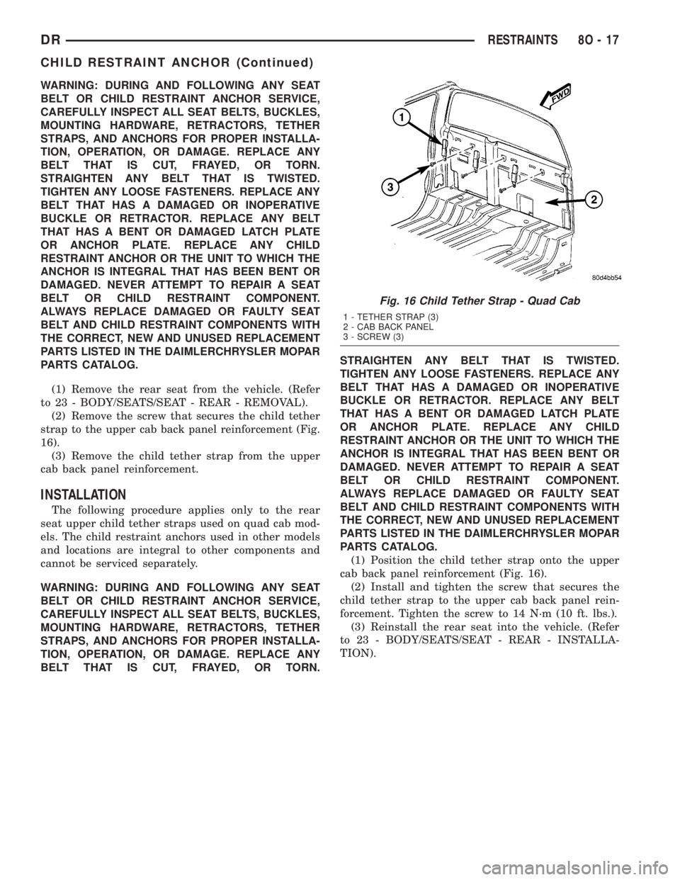
(1) Remove the rear seat from the vehicle. (Refer
to 23 - BODY/SEATS/SEAT - REAR - REMOVAL).
(2) Remove the screw that secures the child tether
strap to the upper cab back panel reinforcement (Fig.
16).
(3) Remove the child tether strap from the upper
cab back panel reinforcement.
INSTALLATION
The following procedure applies only to the rear
seat upper child tether straps used on quad cab mod-
els. The child restraint anchors used in other models
and locations are integral to other components and
cannot be serviced separately.
WARNING: DURING AND FOLLOWING ANY SEAT
BELT OR CHILD RESTRAINT ANCHOR SERVICE,
CAREFULLY INSPECT ALL SEAT BELTS, BUCKLES,
MOUNTING HARDWARE, RETRACTORS, TETHER
STRAPS, AND ANCHORS FOR PROPER INSTALLA-
TION, OPERATION, OR DAMAGE. REPLACE ANY
BELT THAT IS CUT, FRAYED, OR TORN.STRAIGHTEN ANY BELT THAT IS TWISTED.
TIGHTEN ANY LOOSE FASTENERS. REPLACE ANY
BELT THAT HAS A DAMAGED OR INOPERATIVE
BUCKLE OR RETRACTOR. REPLACE ANY BELT
THAT HAS A BENT OR DAMAGED LATCH PLATE
OR ANCHOR PLATE. REPLACE ANY CHILD
RESTRAINT ANCHOR OR THE UNIT TO WHICH THE
ANCHOR IS INTEGRAL THAT HAS BEEN BENT OR
DAMAGED. NEVER ATTEMPT TO REPAIR A SEAT
BELT OR CHILD RESTRAINT COMPONENT.
ALWAYS REPLACE DAMAGED OR FAULTY SEAT
BELT AND CHILD RESTRAINT COMPONENTS WITH
THE CORRECT, NEW AND UNUSED REPLACEMENT
PARTS LISTED IN THE DAIMLERCHRYSLER MOPAR
PARTS CATALOG.
(1) Position the child tether strap onto the upper
cab back panel reinforcement (Fig. 16).
(2) Install and tighten the screw that secures the
child tether strap to the upper cab back panel rein-
forcement. Tighten the screw to 14 N´m (10 ft. lbs.).
(3) Reinstall the rear seat into the vehicle. (Refer
to 23 - BODY/SEATS/SEAT - REAR - INSTALLA-
TION).
Fig. 16 Child Tether Strap - Quad Cab
1 - TETHER STRAP (3)
2 - CAB BACK PANEL
3 - SCREW (3)
DRRESTRAINTS 8O - 17
CHILD RESTRAINT ANCHOR (Continued)
Page 626 of 2895
steering wheel hub area are not pinched between the
driver airbag and the steering wheel armature.
(5) Install and tighten the two screws that secure
the driver airbag to the steering wheel armature.
Tighten the screws to 14 N´m (120 in. lbs.).
(6) From the top of the steering wheel, position the
two trim covers or speed control switches into the
pockets on each side of the driver airbag trim cover.
(7) From the underside of the steering wheel,
install and tighten the two screws that secure the
two trim covers or speed control switches to each side
of the driver airbag trim cover. Tighten the screws to
2 N´m (15 in. lbs.).
(8) Do not reconnect the battery negative cable at
this time. The supplemental restraint system verifi-
cation test procedure should be performed following
service of any supplemental restraint system compo-
nent. (Refer to 8 - ELECTRICAL/RESTRAINTS -
STANDARD PROCEDURE - VERIFICATION TEST).
FRONT CENTER SEAT BELT &
RETRACTOR
REMOVAL
A front center seat belt and retractor is used only
on standard cab models. Quad cab models have a lap
belt in the front center seating position. (Refer to 8 -
ELECTRICAL/RESTRAINTS/FRONT CENTER
SEAT BELT BUCKLE - REMOVAL).
WARNING: DURING AND FOLLOWING ANY SEAT
BELT OR CHILD RESTRAINT ANCHOR SERVICE,
CAREFULLY INSPECT ALL SEAT BELTS, BUCKLES,
MOUNTING HARDWARE, RETRACTORS, TETHER
STRAPS, AND ANCHORS FOR PROPER INSTALLA-
TION, OPERATION, OR DAMAGE. REPLACE ANY
BELT THAT IS CUT, FRAYED, OR TORN.
STRAIGHTEN ANY BELT THAT IS TWISTED.
TIGHTEN ANY LOOSE FASTENERS. REPLACE ANY
BELT THAT HAS A DAMAGED OR INOPERATIVE
BUCKLE OR RETRACTOR. REPLACE ANY BELT
THAT HAS A BENT OR DAMAGED LATCH PLATE
OR ANCHOR PLATE. REPLACE ANY CHILD
RESTRAINT ANCHOR OR THE UNIT TO WHICH THE
ANCHOR IS INTEGRAL THAT HAS BEEN BENT OR
DAMAGED. NEVER ATTEMPT TO REPAIR A SEAT
BELT OR CHILD RESTRAINT COMPONENT.
ALWAYS REPLACE DAMAGED OR FAULTY SEAT
BELT AND CHILD RESTRAINT COMPONENTS WITH
THE CORRECT, NEW AND UNUSED REPLACEMENT
PARTS LISTED IN THE DAIMLERCHRYSLER MOPAR
PARTS CATALOG.
(1) Reach between the center of the front seat
cushion and front seat back to access and unbucklethe front center seat belt lower anchor latch plate
from the unique black, keyed lower anchor buckle.
Use an ignition key or a small screwdriver to depress
the small white release button on the anchor buckle.
(2) Move the front seat to its most forward position
for easiest access to the front center seat belt and
retractor unit.
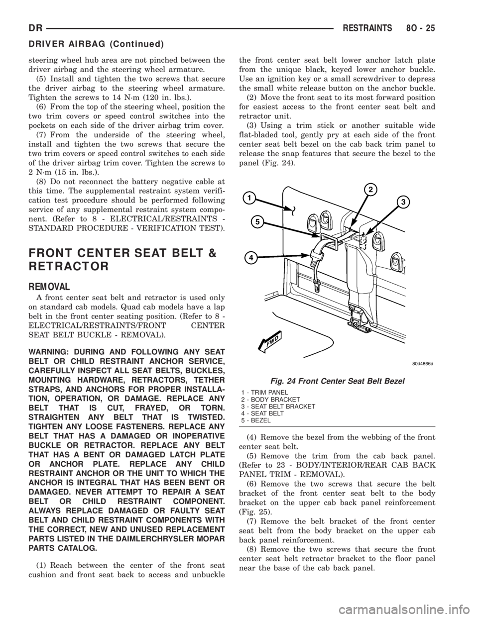
(3) Using a trim stick or another suitable wide
flat-bladed tool, gently pry at each side of the front
center seat belt bezel on the cab back trim panel to
release the snap features that secure the bezel to the
panel (Fig. 24).
(4) Remove the bezel from the webbing of the front
center seat belt.
(5) Remove the trim from the cab back panel.
(Refer to 23 - BODY/INTERIOR/REAR CAB BACK
PANEL TRIM - REMOVAL).
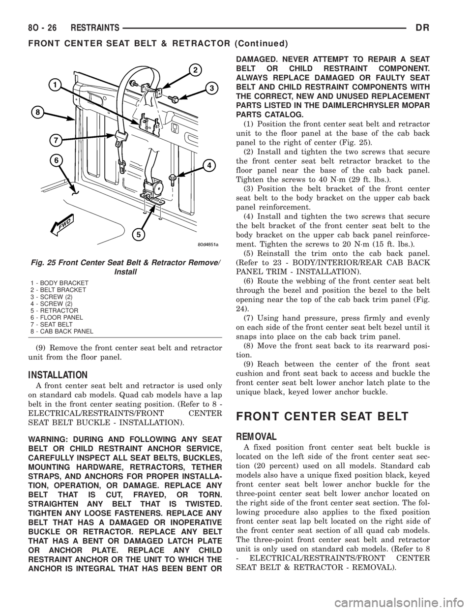
(6) Remove the two screws that secure the belt
bracket of the front center seat belt to the body
bracket on the upper cab back panel reinforcement
(Fig. 25).
(7) Remove the belt bracket of the front center
seat belt from the body bracket on the upper cab
back panel reinforcement.
(8) Remove the two screws that secure the front
center seat belt retractor bracket to the floor panel
near the base of the cab back panel.
Fig. 24 Front Center Seat Belt Bezel
1 - TRIM PANEL
2 - BODY BRACKET
3 - SEAT BELT BRACKET
4 - SEAT BELT
5 - BEZEL
DRRESTRAINTS 8O - 25
DRIVER AIRBAG (Continued)
Page 627 of 2895
(9) Remove the front center seat belt and retractor
unit from the floor panel.
INSTALLATION
A front center seat belt and retractor is used only
on standard cab models. Quad cab models have a lap
belt in the front center seating position. (Refer to 8 -
ELECTRICAL/RESTRAINTS/FRONT CENTER
SEAT BELT BUCKLE - INSTALLATION).
WARNING: DURING AND FOLLOWING ANY SEAT
BELT OR CHILD RESTRAINT ANCHOR SERVICE,
CAREFULLY INSPECT ALL SEAT BELTS, BUCKLES,
MOUNTING HARDWARE, RETRACTORS, TETHER
STRAPS, AND ANCHORS FOR PROPER INSTALLA-
TION, OPERATION, OR DAMAGE. REPLACE ANY
BELT THAT IS CUT, FRAYED, OR TORN.
STRAIGHTEN ANY BELT THAT IS TWISTED.
TIGHTEN ANY LOOSE FASTENERS. REPLACE ANY
BELT THAT HAS A DAMAGED OR INOPERATIVE
BUCKLE OR RETRACTOR. REPLACE ANY BELT
THAT HAS A BENT OR DAMAGED LATCH PLATE
OR ANCHOR PLATE. REPLACE ANY CHILD
RESTRAINT ANCHOR OR THE UNIT TO WHICH THE
ANCHOR IS INTEGRAL THAT HAS BEEN BENT ORDAMAGED. NEVER ATTEMPT TO REPAIR A SEAT
BELT OR CHILD RESTRAINT COMPONENT.
ALWAYS REPLACE DAMAGED OR FAULTY SEAT
BELT AND CHILD RESTRAINT COMPONENTS WITH
THE CORRECT, NEW AND UNUSED REPLACEMENT
PARTS LISTED IN THE DAIMLERCHRYSLER MOPAR
PARTS CATALOG.
(1) Position the front center seat belt and retractor
unit to the floor panel at the base of the cab back
panel to the right of center (Fig. 25).
(2) Install and tighten the two screws that secure
the front center seat belt retractor bracket to the
floor panel near the base of the cab back panel.
Tighten the screws to 40 N´m (29 ft. lbs.).
(3) Position the belt bracket of the front center
seat belt to the body bracket on the upper cab back
panel reinforcement.
(4) Install and tighten the two screws that secure
the belt bracket of the front center seat belt to the
body bracket on the upper cab back panel reinforce-
ment. Tighten the screws to 20 N´m (15 ft. lbs.).
(5) Reinstall the trim onto the cab back panel.
(Refer to 23 - BODY/INTERIOR/REAR CAB BACK
PANEL TRIM - INSTALLATION).
(6) Route the webbing of the front center seat belt
through the bezel and position the bezel to the belt
opening near the top of the cab back trim panel (Fig.
24).
(7) Using hand pressure, press firmly and evenly
on each side of the front center seat belt bezel until it
snaps into place on the cab back trim panel.
(8) Move the front seat back to its rearward posi-
tion.
(9) Reach between the center of the front seat
cushion and front seat back to access and buckle the
front center seat belt lower anchor latch plate to the
unique black, keyed lower anchor buckle.
FRONT CENTER SEAT BELT
REMOVAL
A fixed position front center seat belt buckle is
located on the left side of the front center seat sec-
tion (20 percent) used on all models. Standard cab
models also have a unique fixed position black, keyed
front center seat belt lower anchor buckle for the
three-point center seat belt lower anchor located on
the right side of the front center seat section. The fol-
lowing procedure also applies to the fixed position
front center seat lap belt located on the right side of
the front center seat section of all quad cab models.
The three-point front center seat belt and retractor
unit is only used on standard cab models. (Refer to 8
- ELECTRICAL/RESTRAINTS/FRONT CENTER
SEAT BELT & RETRACTOR - REMOVAL).
Fig. 25 Front Center Seat Belt & Retractor Remove/
Install
1 - BODY BRACKET
2 - BELT BRACKET
3 - SCREW (2)
4 - SCREW (2)
5 - RETRACTOR
6 - FLOOR PANEL
7 - SEAT BELT
8 - CAB BACK PANEL
8O - 26 RESTRAINTSDR
FRONT CENTER SEAT BELT & RETRACTOR (Continued)
Page 628 of 2895
WARNING: DURING AND FOLLOWING ANY SEAT
BELT OR CHILD RESTRAINT ANCHOR SERVICE,
CAREFULLY INSPECT ALL SEAT BELTS, BUCKLES,
MOUNTING HARDWARE, RETRACTORS, TETHER
STRAPS, AND ANCHORS FOR PROPER INSTALLA-
TION, OPERATION, OR DAMAGE. REPLACE ANY
BELT THAT IS CUT, FRAYED, OR TORN.
STRAIGHTEN ANY BELT THAT IS TWISTED.
TIGHTEN ANY LOOSE FASTENERS. REPLACE ANY
BELT THAT HAS A DAMAGED OR INOPERATIVE
BUCKLE OR RETRACTOR. REPLACE ANY BELT
THAT HAS A BENT OR DAMAGED LATCH PLATE
OR ANCHOR PLATE. REPLACE ANY CHILD
RESTRAINT ANCHOR OR THE UNIT TO WHICH THE
ANCHOR IS INTEGRAL THAT HAS BEEN BENT OR
DAMAGED. NEVER ATTEMPT TO REPAIR A SEAT
BELT OR CHILD RESTRAINT COMPONENT.
ALWAYS REPLACE DAMAGED OR FAULTY SEAT
BELT AND CHILD RESTRAINT COMPONENTS WITH
THE CORRECT, NEW AND UNUSED REPLACEMENT
PARTS LISTED IN THE DAIMLERCHRYSLER MOPAR
PARTS CATALOG.
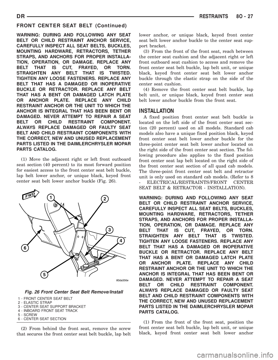
(1) Move the adjacent right or left front outboard
seat section (40 percent) to its most forward position
for easiest access to the front center seat belt buckle,
lap belt lower anchor, or unique black, keyed front
center seat belt lower anchor buckle (Fig. 26).
(2) From behind the front seat, remove the screw
that secures the front center seat belt buckle, lap beltlower anchor, or unique black, keyed front center
seat belt lower anchor buckle to the center seat sup-
port bracket.
(3) From the front of the front seat, reach between
the center seat cushion and the adjacent right or left
front outboard seat cushion to access and remove the
front center seat belt buckle, lap belt unit, or unique
black, keyed front center seat belt lower anchor
buckle through the elastic strap on the side of the
center seat cushion.
(4) Remove the front center seat belt buckle, lap
belt unit, or unique black, keyed front center seat
belt lower anchor buckle from the front seat.
INSTALLATION
A fixed position front center seat belt buckle is
located on the left side of the front center seat sec-
tion (20 percent) used on all models. Standard cab
models also have a unique fixed position black, keyed
front center seat belt lower anchor buckle for the
three-point center seat belt lower anchor located on
the right side of the front center seat section. The fol-
lowing procedure also applies to the fixed position
front center seat lap belt located on the right side of
the front center seat section of all quad cab models.
The three-point front center seat belt and retractor
unit is only used on standard cab models. (Refer to 8
- ELECTRICAL/RESTRAINTS/FRONT CENTER
SEAT BELT & RETRACTOR - INSTALLATION).
WARNING: DURING AND FOLLOWING ANY SEAT
BELT OR CHILD RESTRAINT ANCHOR SERVICE,
CAREFULLY INSPECT ALL SEAT BELTS, BUCKLES,
MOUNTING HARDWARE, RETRACTORS, TETHER
STRAPS, AND ANCHORS FOR PROPER INSTALLA-
TION, OPERATION, OR DAMAGE. REPLACE ANY
BELT THAT IS CUT, FRAYED, OR TORN.
STRAIGHTEN ANY BELT THAT IS TWISTED.
TIGHTEN ANY LOOSE FASTENERS. REPLACE ANY
BELT THAT HAS A DAMAGED OR INOPERATIVE
BUCKLE OR RETRACTOR. REPLACE ANY BELT
THAT HAS A BENT OR DAMAGED LATCH PLATE
OR ANCHOR PLATE. REPLACE ANY CHILD
RESTRAINT ANCHOR OR THE UNIT TO WHICH THE
ANCHOR IS INTEGRAL THAT HAS BEEN BENT OR
DAMAGED. NEVER ATTEMPT TO REPAIR A SEAT
BELT OR CHILD RESTRAINT COMPONENT.
ALWAYS REPLACE DAMAGED OR FAULTY SEAT
BELT AND CHILD RESTRAINT COMPONENTS WITH
THE CORRECT, NEW AND UNUSED REPLACEMENT
PARTS LISTED IN THE DAIMLERCHRYSLER MOPAR
PARTS CATALOG.
(1) From the front of the front seat, position the
front center seat belt buckle, lap belt unit, or unique
black, keyed front center seat belt lower anchor
Fig. 26 Front Center Seat Belt Remove/Install
1 - FRONT CENTER SEAT BELT
2 - ELASTIC STRAP
3 - CENTER SEAT SUPPORT BRACKET
4 - INBOARD FRONT SEAT TRACK
5 - SCREW
6 - CENTER SEAT SECTION
DRRESTRAINTS 8O - 27
FRONT CENTER SEAT BELT (Continued)
Page 629 of 2895
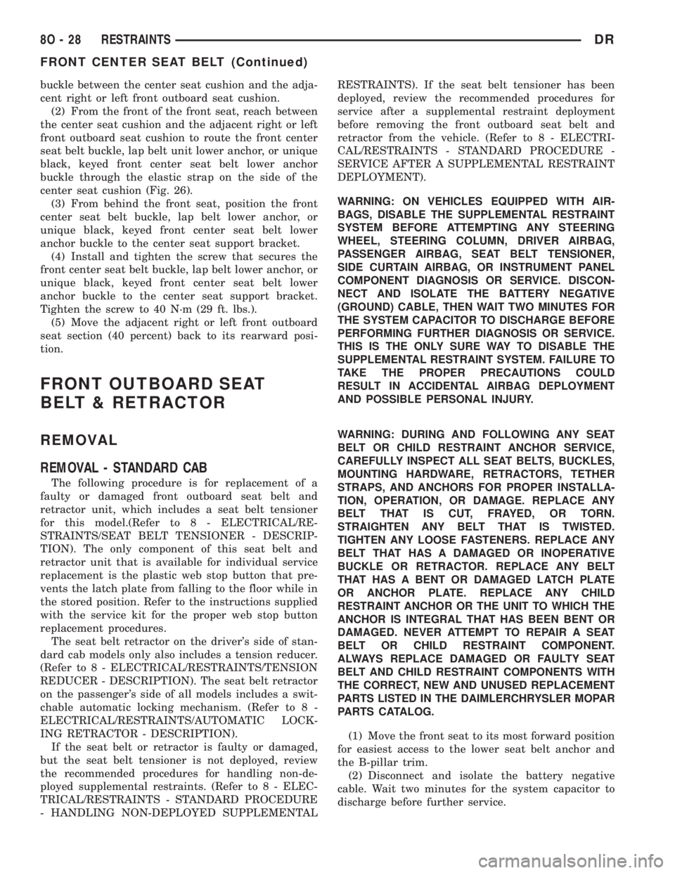
buckle between the center seat cushion and the adja-
cent right or left front outboard seat cushion.
(2) From the front of the front seat, reach between
the center seat cushion and the adjacent right or left
front outboard seat cushion to route the front center
seat belt buckle, lap belt unit lower anchor, or unique
black, keyed front center seat belt lower anchor
buckle through the elastic strap on the side of the
center seat cushion (Fig. 26).
(3) From behind the front seat, position the front
center seat belt buckle, lap belt lower anchor, or
unique black, keyed front center seat belt lower
anchor buckle to the center seat support bracket.
(4) Install and tighten the screw that secures the
front center seat belt buckle, lap belt lower anchor, or
unique black, keyed front center seat belt lower
anchor buckle to the center seat support bracket.
Tighten the screw to 40 N´m (29 ft. lbs.).
(5) Move the adjacent right or left front outboard
seat section (40 percent) back to its rearward posi-
tion.
FRONT OUTBOARD SEAT
BELT & RETRACTOR
REMOVAL
REMOVAL - STANDARD CAB
The following procedure is for replacement of a
faulty or damaged front outboard seat belt and
retractor unit, which includes a seat belt tensioner
for this model.(Refer to 8 - ELECTRICAL/RE-
STRAINTS/SEAT BELT TENSIONER - DESCRIP-
TION). The only component of this seat belt and
retractor unit that is available for individual service
replacement is the plastic web stop button that pre-
vents the latch plate from falling to the floor while in
the stored position. Refer to the instructions supplied
with the service kit for the proper web stop button
replacement procedures.
The seat belt retractor on the driver's side of stan-
dard cab models only also includes a tension reducer.
(Refer to 8 - ELECTRICAL/RESTRAINTS/TENSION
REDUCER - DESCRIPTION). The seat belt retractor
on the passenger's side of all models includes a swit-
chable automatic locking mechanism. (Refer to 8 -
ELECTRICAL/RESTRAINTS/AUTOMATIC LOCK-
ING RETRACTOR - DESCRIPTION).
If the seat belt or retractor is faulty or damaged,
but the seat belt tensioner is not deployed, review
the recommended procedures for handling non-de-
ployed supplemental restraints. (Refer to 8 - ELEC-
TRICAL/RESTRAINTS - STANDARD PROCEDURE
- HANDLING NON-DEPLOYED SUPPLEMENTALRESTRAINTS). If the seat belt tensioner has been
deployed, review the recommended procedures for
service after a supplemental restraint deployment
before removing the front outboard seat belt and
retractor from the vehicle. (Refer to 8 - ELECTRI-
CAL/RESTRAINTS - STANDARD PROCEDURE -
SERVICE AFTER A SUPPLEMENTAL RESTRAINT
DEPLOYMENT).
WARNING: ON VEHICLES EQUIPPED WITH AIR-
BAGS, DISABLE THE SUPPLEMENTAL RESTRAINT
SYSTEM BEFORE ATTEMPTING ANY STEERING
WHEEL, STEERING COLUMN, DRIVER AIRBAG,
PASSENGER AIRBAG, SEAT BELT TENSIONER,
SIDE CURTAIN AIRBAG, OR INSTRUMENT PANEL
COMPONENT DIAGNOSIS OR SERVICE. DISCON-
NECT AND ISOLATE THE BATTERY NEGATIVE
(GROUND) CABLE, THEN WAIT TWO MINUTES FOR
THE SYSTEM CAPACITOR TO DISCHARGE BEFORE
PERFORMING FURTHER DIAGNOSIS OR SERVICE.
THIS IS THE ONLY SURE WAY TO DISABLE THE
SUPPLEMENTAL RESTRAINT SYSTEM. FAILURE TO
TAKE THE PROPER PRECAUTIONS COULD
RESULT IN ACCIDENTAL AIRBAG DEPLOYMENT
AND POSSIBLE PERSONAL INJURY.
WARNING: DURING AND FOLLOWING ANY SEAT
BELT OR CHILD RESTRAINT ANCHOR SERVICE,
CAREFULLY INSPECT ALL SEAT BELTS, BUCKLES,
MOUNTING HARDWARE, RETRACTORS, TETHER
STRAPS, AND ANCHORS FOR PROPER INSTALLA-
TION, OPERATION, OR DAMAGE. REPLACE ANY
BELT THAT IS CUT, FRAYED, OR TORN.
STRAIGHTEN ANY BELT THAT IS TWISTED.
TIGHTEN ANY LOOSE FASTENERS. REPLACE ANY
BELT THAT HAS A DAMAGED OR INOPERATIVE
BUCKLE OR RETRACTOR. REPLACE ANY BELT
THAT HAS A BENT OR DAMAGED LATCH PLATE
OR ANCHOR PLATE. REPLACE ANY CHILD
RESTRAINT ANCHOR OR THE UNIT TO WHICH THE
ANCHOR IS INTEGRAL THAT HAS BEEN BENT OR
DAMAGED. NEVER ATTEMPT TO REPAIR A SEAT
BELT OR CHILD RESTRAINT COMPONENT.
ALWAYS REPLACE DAMAGED OR FAULTY SEAT
BELT AND CHILD RESTRAINT COMPONENTS WITH
THE CORRECT, NEW AND UNUSED REPLACEMENT
PARTS LISTED IN THE DAIMLERCHRYSLER MOPAR
PARTS CATALOG.
(1) Move the front seat to its most forward position
for easiest access to the lower seat belt anchor and
the B-pillar trim.
(2) Disconnect and isolate the battery negative
cable. Wait two minutes for the system capacitor to
discharge before further service.
8O - 28 RESTRAINTSDR
FRONT CENTER SEAT BELT (Continued)
Page 631 of 2895
WARNING: ON VEHICLES EQUIPPED WITH AIR-
BAGS, DISABLE THE SUPPLEMENTAL RESTRAINT
SYSTEM BEFORE ATTEMPTING ANY STEERING
WHEEL, STEERING COLUMN, DRIVER AIRBAG,
PASSENGER AIRBAG, SEAT BELT TENSIONER,
SIDE CURTAIN AIRBAG, OR INSTRUMENT PANEL
COMPONENT DIAGNOSIS OR SERVICE. DISCON-
NECT AND ISOLATE THE BATTERY NEGATIVE
(GROUND) CABLE, THEN WAIT TWO MINUTES FOR
THE SYSTEM CAPACITOR TO DISCHARGE BEFORE
PERFORMING FURTHER DIAGNOSIS OR SERVICE.
THIS IS THE ONLY SURE WAY TO DISABLE THE
SUPPLEMENTAL RESTRAINT SYSTEM. FAILURE TO
TAKE THE PROPER PRECAUTIONS COULD
RESULT IN ACCIDENTAL AIRBAG DEPLOYMENT
AND POSSIBLE PERSONAL INJURY.
WARNING: DURING AND FOLLOWING ANY SEAT
BELT OR CHILD RESTRAINT ANCHOR SERVICE,
CAREFULLY INSPECT ALL SEAT BELTS, BUCKLES,
MOUNTING HARDWARE, RETRACTORS, TETHER
STRAPS, AND ANCHORS FOR PROPER INSTALLA-
TION, OPERATION, OR DAMAGE. REPLACE ANY
BELT THAT IS CUT, FRAYED, OR TORN.
STRAIGHTEN ANY BELT THAT IS TWISTED.
TIGHTEN ANY LOOSE FASTENERS. REPLACE ANY
BELT THAT HAS A DAMAGED OR INOPERATIVE
BUCKLE OR RETRACTOR. REPLACE ANY BELT
THAT HAS A BENT OR DAMAGED LATCH PLATE
OR ANCHOR PLATE. REPLACE ANY CHILD
RESTRAINT ANCHOR OR THE UNIT TO WHICH THE
ANCHOR IS INTEGRAL THAT HAS BEEN BENT OR
DAMAGED. NEVER ATTEMPT TO REPAIR A SEAT
BELT OR CHILD RESTRAINT COMPONENT.
ALWAYS REPLACE DAMAGED OR FAULTY SEAT
BELT AND CHILD RESTRAINT COMPONENTS WITH
THE CORRECT, NEW AND UNUSED REPLACEMENT
PARTS LISTED IN THE DAIMLERCHRYSLER MOPAR
PARTS CATALOG.
(1) Move the front seat to its most forward position
for easiest access to the lower seat belt anchor and
the B-pillar trim.
(2) Disconnect and isolate the battery negative
cable. Wait two minutes for the system capacitor to
discharge before further service.
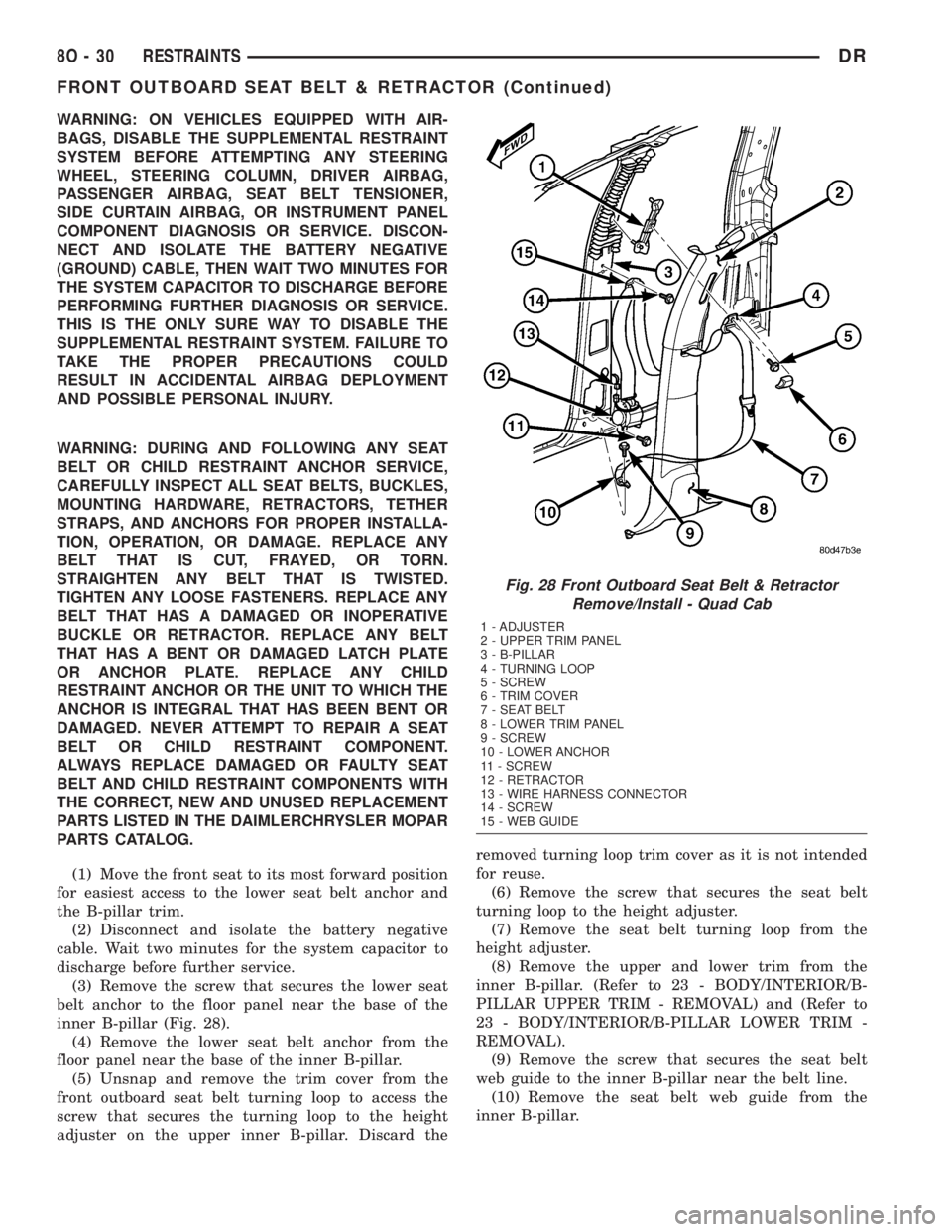
(3) Remove the screw that secures the lower seat
belt anchor to the floor panel near the base of the
inner B-pillar (Fig. 28).
(4) Remove the lower seat belt anchor from the
floor panel near the base of the inner B-pillar.
(5) Unsnap and remove the trim cover from the
front outboard seat belt turning loop to access the
screw that secures the turning loop to the height
adjuster on the upper inner B-pillar. Discard theremoved turning loop trim cover as it is not intended
for reuse.
(6) Remove the screw that secures the seat belt
turning loop to the height adjuster.
(7) Remove the seat belt turning loop from the
height adjuster.
(8) Remove the upper and lower trim from the
inner B-pillar. (Refer to 23 - BODY/INTERIOR/B-
PILLAR UPPER TRIM - REMOVAL) and (Refer to
23 - BODY/INTERIOR/B-PILLAR LOWER TRIM -
REMOVAL).
(9) Remove the screw that secures the seat belt
web guide to the inner B-pillar near the belt line.
(10) Remove the seat belt web guide from the
inner B-pillar.
Fig. 28 Front Outboard Seat Belt & Retractor
Remove/Install - Quad Cab
1 - ADJUSTER
2 - UPPER TRIM PANEL
3 - B-PILLAR
4 - TURNING LOOP
5 - SCREW
6 - TRIM COVER
7 - SEAT BELT
8 - LOWER TRIM PANEL
9 - SCREW
10 - LOWER ANCHOR
11 - SCREW
12 - RETRACTOR
13 - WIRE HARNESS CONNECTOR
14 - SCREW
15 - WEB GUIDE
8O - 30 RESTRAINTSDR
FRONT OUTBOARD SEAT BELT & RETRACTOR (Continued)