Page 209 of 1690
1209J±02
A77127
Ohmmeter
Resistance
A77128No ContinuityOhmmeter
A77129
Vacuum
A77130
6V Vacuum 12±18
± EMISSION CONTROLEGR SYSTEM (1CD±FTV)
AVENSIS REPAIR MANUAL (RM1018E)
INSPECTION
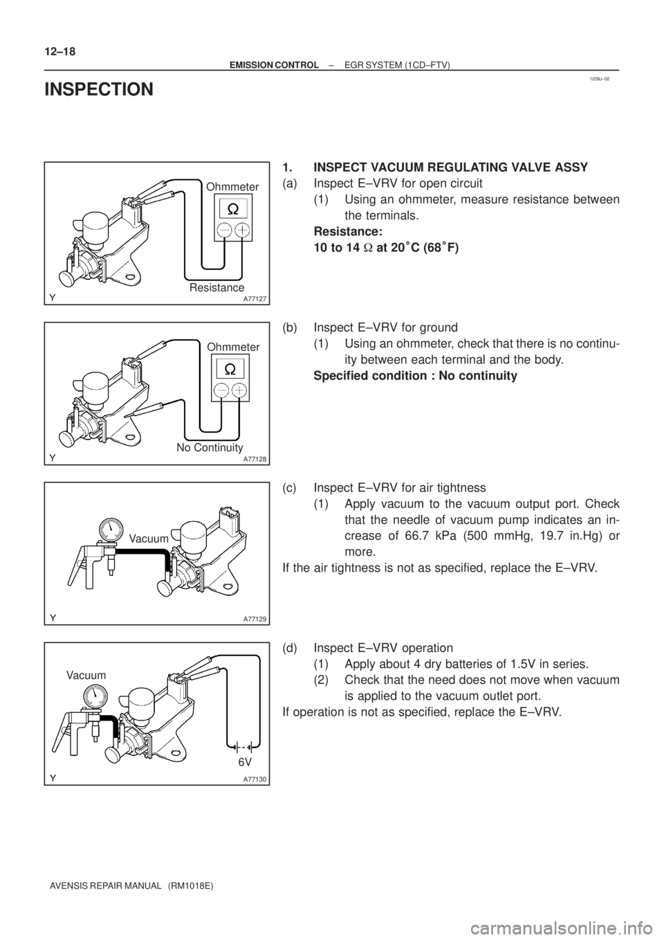
1. INSPECT VACUUM REGULATING VALVE ASSY
(a) Inspect E±VRV for open circuit
(1) Using an ohmmeter, measure resistance between
the terminals.
Resistance:
10 to 14 � at 20�C (68�F)
(b) Inspect E±VRV for ground
(1) Using an ohmmeter, check that there is no continu-
ity between each terminal and the body.
Specified condition : No continuity
(c) Inspect E±VRV for air tightness
(1) Apply vacuum to the vacuum output port. Check
that the needle of vacuum pump indicates an in-
crease of 66.7 kPa (500 mmHg, 19.7 in.Hg) or
more.
If the air tightness is not as specified, replace the E±VRV.
(d) Inspect E±VRV operation
(1) Apply about 4 dry batteries of 1.5V in series.
(2) Check that the need does not move when vacuum
is applied to the vacuum outlet port.
If operation is not as specified, replace the E±VRV.
Page 210 of 1690
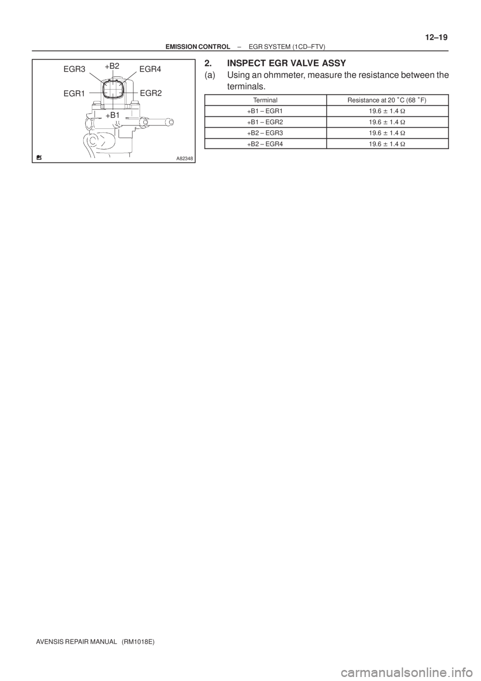
A82348
+B2
+B1EGR2
EGR1EGR4 EGR3
± EMISSION CONTROLEGR SYSTEM (1CD±FTV)
12±19
AVENSIS REPAIR MANUAL (RM1018E)
2. INSPECT EGR VALVE ASSY
(a) Using an ohmmeter, measure the resistance between the
terminals.
TerminalResistance at 20 �C (68 �F)
+B1 ± EGR119.6 � 1.4 �
+B1 ± EGR219.6 � 1.4 �
+B2 ± EGR319.6 � 1.4 �
+B2 ± EGR419.6 � 1.4 �
Page 211 of 1690
1209I±02
± EMISSION CONTROLEGR SYSTEM (1CD±FTV)
12±17
AVENSIS REPAIR MANUAL (RM1018E)
EGR SYSTEM (1CD±FTV)
ON±VEHICLE INSPECTION
HINT:
In a malfunction where the EGR system is always on, black smoke or white smoke may be emitted from the
exhaust pipe. If this occurs, inspect the EGR system as well.
1. INSPECT SEATING OF EGR VALVE
(a) Start the engine and check that it starts and runs at idle.
2. INSPECT HOT ENGINE CONDITION (WHEN USING HAND±HELD TESTER)
(a) Connect the hand±held tester to the DLC3.
(b) Start the engine and run it at idle.
(c) Select the ACTIVE TEST mode on the hand±held tester.
HINT:
Refer to the hand±held tester operator's manual for further details.
(d) Warm up the engine, the coolant temperature should be above 75�C (109�F) and bellow 90�C
(194�F).
(e) Check that the AFM reading is 5�ega�8 g/s with the engine idling.
(f) Operate the EGR valve with a hand±held tester. Regulate the valve opening angle to 0, and check that
the AFM reading is 11�ega�17 g/s..
If the AFM reading is out of range in either (e) or (f), replace the EGR valve.
If the AFM is out of range in both (e) and (f), replace the air flow meter (air cleaner) and check the EGR valve
operation again.
3. INSPECT HOT ENGINE CONDITION (WHEN NOT USING HAND±HELD TESTER)
(a) Install the vacuum gauge.
(1) Using a 3±way connector, connect a vacuum gauge to the hose between the intake manifold and
the turbo pressure sensor.
(b) Warm up the engine, the coolant temperature should be above 75�C (109�F) and bellow 90�C
(194�F).
(c) Check that the vacuum gauge indicates about more than 2.5 kPa (19 mmHg 0.7 in Hg).
(d) Stop the engine (IG OFF), remove the EGR valve connector, restart the engine, and check that load
under idling is less than 2.5 kPa (19 mmHg 0.7 in Hg).
If the load pressure exceeds the above value, replace the EGR valve.
Page 542 of 1690
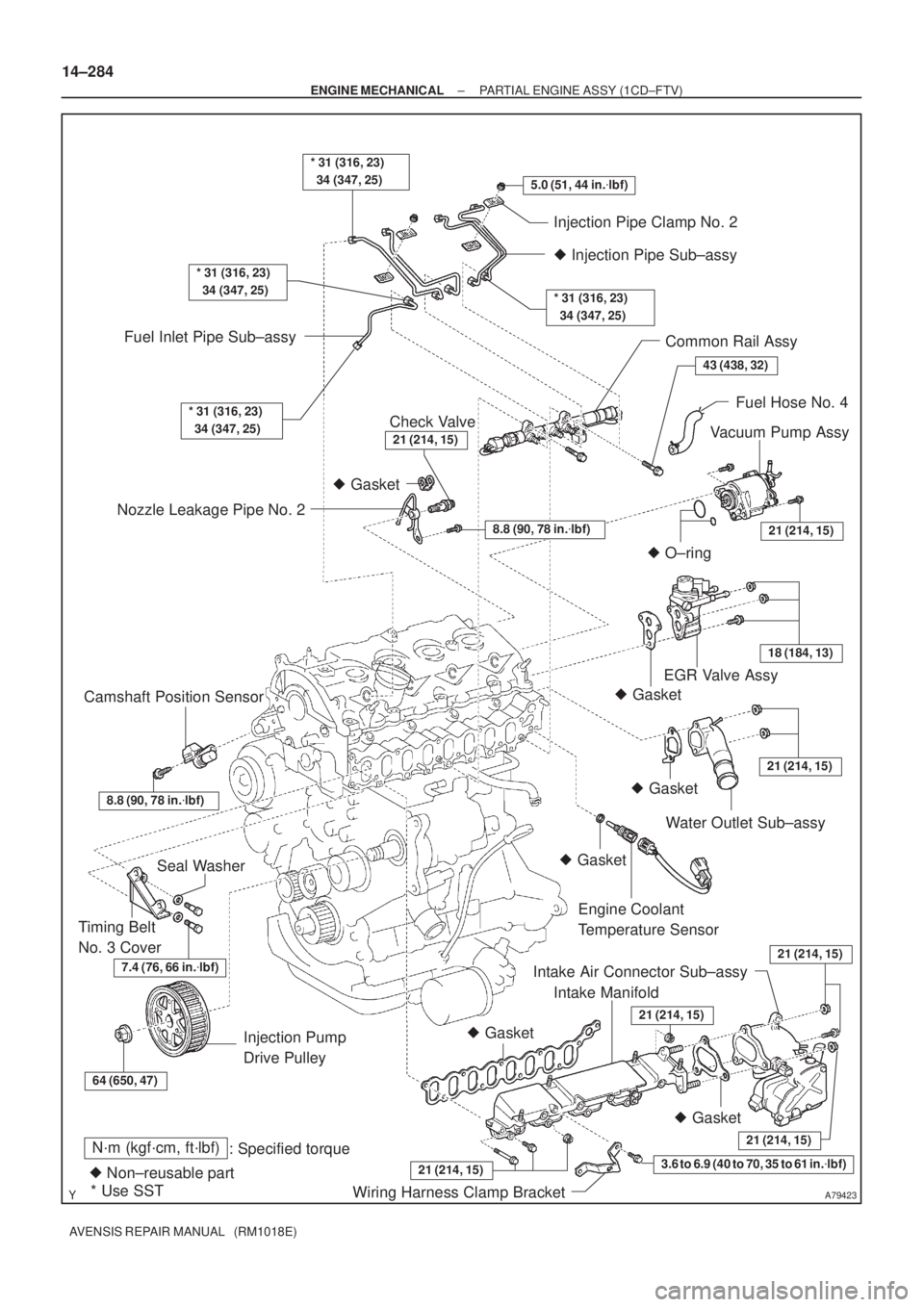
A79423
N´m (kgf´cm, ft´lbf)
: Specified torque
� Non±reusable part� Gasket
� O±ring
* Use SST� Gasket � Gasket
� Gasket
� Gasket
� Gasket3.6 to 6.9 (40 to 70, 35 to 61 in.�lbf)
5.0 (51, 44 in.�lbf)
7.4 (76, 66 in.�lbf)
* 31 (316, 23)
34 (347, 25)
43 (438, 32)
21 (214, 15)
18 (184, 13)
21 (214, 15)
21 (214, 15)
21 (214, 15)
64 (650, 47)
21 (214, 15)
* 31 (316, 23)
34 (347, 25)
* 31 (316, 23)
34 (347, 25)
Injection Pipe Clamp No. 2
� Injection Pipe Sub±assy
* 31 (316, 23)
34 (347, 25)
Common Rail Assy
Fuel Hose No. 4
Vacuum Pump Assy
Nozzle Leakage Pipe No. 2Fuel Inlet Pipe Sub±assy
EGR Valve Assy
Water Outlet Sub±assy
Engine Coolant
Temperature Sensor
Intake Air Connector Sub±assy
Intake Manifold
Wiring Harness Clamp Bracket Injection Pump
Drive Pulley Timing Belt
No. 3 CoverSeal Washer Camshaft Position Sensor
Check Valve
8.8 (90, 78 in.�lbf)
8.8 (90, 78 in.�lbf)
21 (214, 15)
21 (214, 15)
14±284
± ENGINE MECHANICALPARTIAL ENGINE ASSY (1CD±FTV)
AVENSIS REPAIR MANUAL (RM1018E)
Page 550 of 1690
A80118
A80115
A80116
A09660
14±292
±
ENGINE MECHANICAL PARTIAL ENGINE ASSY(1CD±FTV)
AVENSIS REPAIR MANUAL (RM1018E)
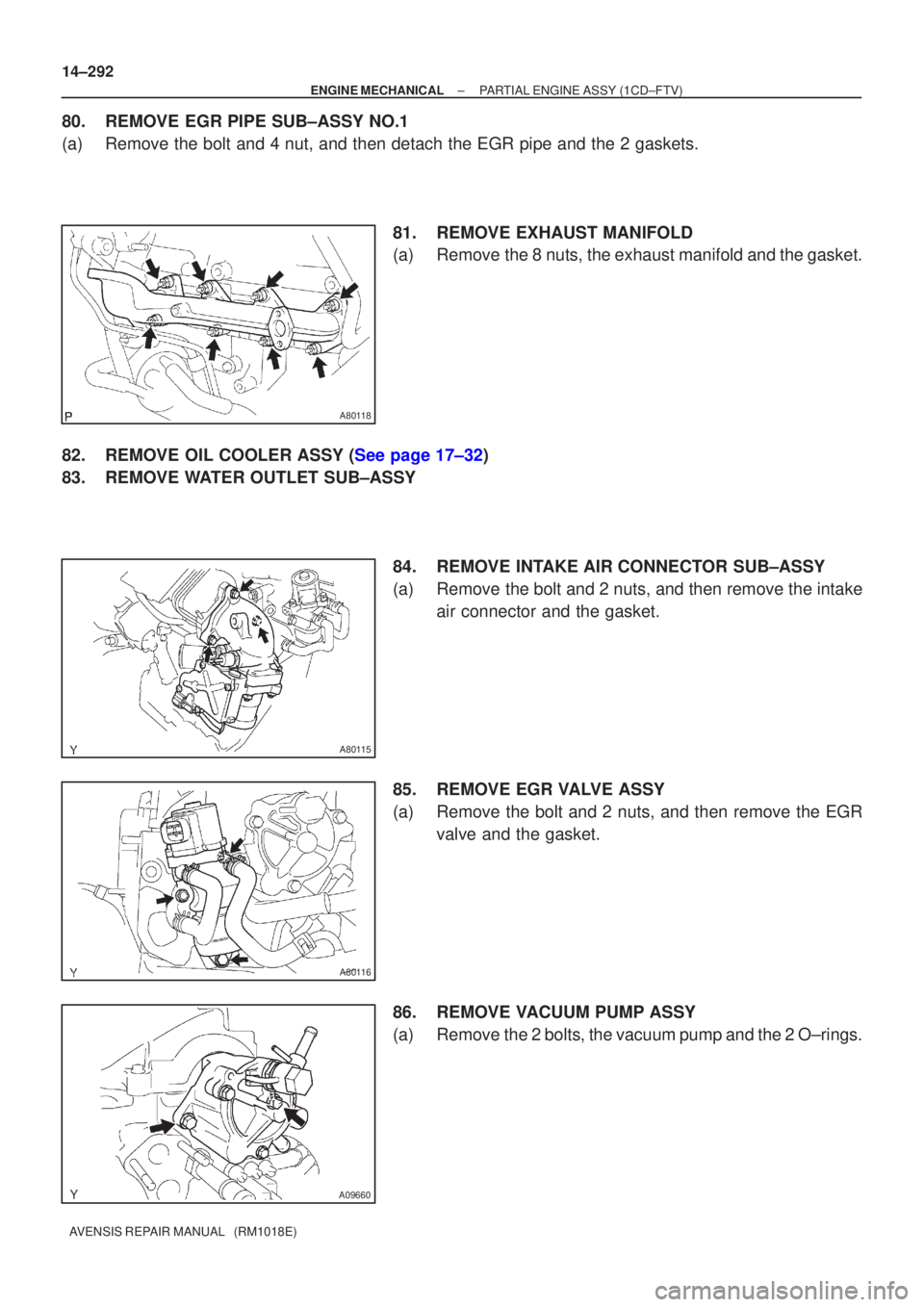
80.REMOVE EGR PIPE SUB±ASSY NO.1
(a)Remove the bolt and 4 nut, and then detach the EGR pipe and the 2 gasket\
s. 81.REMOVE EXHAUST MANIFOLD
(a)Remove the 8 nuts, the exhaust manifold and the gasket.
82.REMOVE OIL COOLER ASSY (See page 17±32)
83. REMOVE WATER OUTLET SUB±ASSY 84. REMOVE INTAKE AIR CONNECTOR SUB±ASSY
(a) Remove the bolt and 2 nuts, and then remove the intakeair connector and the gasket.
85. REMOVE EGR VALVE ASSY
(a) Remove the bolt and 2 nuts, and then remove the EGR valve and the gasket.
86. REMOVE VACUUM PUMP ASSY
(a) Remove the 2 bolts, the vacuum pump and the 2 O±rings.
Page 557 of 1690
A79196
New O±Ring
New O±Ring
A79182
Collar
Groove
±
ENGINE MECHANICAL PARTIAL ENGINE ASSY(1CD±FTV)
14±299
AVENSIS REPAIR MANUAL (RM1018E)
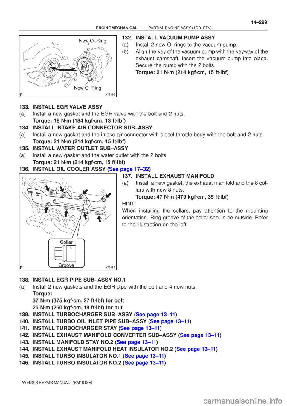
132.INSTALL VACUUM PUMP ASSY
(a)Install 2 new O±rings to the vacuum pump.
(b)Align the key of the vacuum pump with the keyway of the
exhaust camshaft, insert the vacuum pump into place.
Secure the pump with the 2 bolts.
Torque: 21 N �m (214 kgf �cm, 15 ft �lbf)
133.INSTALL EGR VALVE ASSY
(a)Install a new gasket and the EGR valve with the bolt and 2 nuts. Torque: 18 N �m (184 kgf �cm, 13 ft �lbf)
134.INSTALL INTAKE AIR CONNECTOR SUB±ASSY
(a)Install a new gasket and the intake air connector with diesel throttle b\
ody with the bolt and 2 nuts. Torque: 21 N �m (214 kgf �cm, 15 ft �lbf)
135.INSTALL WATER OUTLET SUB±ASSY
(a)Install a new gasket and the water outlet with the 2 bolts. Torque: 21 N �m (214 kgf �cm,15 ft �lbf)
136.INSTALL OIL COOLER ASSY (See page 17±32)
137.INSTALL EXHAUST MANIFOLD
(a)Install a new gasket, the exhaust manifold and the 8 col-lars with new 8 nuts.
Torque: 47 N �m (479 kgf �cm, 35 ft �lbf)
HINT:
When installing the collars, pay attention to the mounting
orientation. Ring groove of the collar should be outside. Refer
to the illustration on the left.
138.INSTALL EGR PIPE SUB±ASSY NO.1
(a)Install 2 new gaskets and the EGR pipe with the bolt and 4 new nuts. Torque:
37 N�m (375 kgf �cm,27 ft �lbf) for bolt
25 N �m (250 kgf �cm,18 ft �lbf) for nut
139.INSTALL TURBOCHARGER SUB±ASSY (See page 13±11)
140.INSTALL TURBO OIL INLET PIPE SUB±ASSY (See page 13±11)
141.INSTALL TURBOCHARGER STAY (See page 13±11)
142.INSTALL EXHAUST MANIFOLD CONVERTER SUB±ASSY (See page 13±11)
143.INSTALL MANIFOLD STAY NO.2 (See page 13±11)
144.INSTALL EXHAUST MANIFOLD HEAT INSULATOR NO.2 (See page 13±11)
145.INSTALL TURBO INSULATOR NO.1 (See page 13±11)
146.INSTALL TURBO INSULATOR NO.2 (See page 13±11)
Page 1007 of 1690
D26613
Example:
D25080
Negative (±)
Terminal
± INTRODUCTIONREPAIR INSTRUCTION
01±15
AVENSIS REPAIR MANUAL (RM1018E)
(8) Oil or water should not be put on the front seat outer belt and the front seat outer belt should be
cleaned with the appropriate detergents.
(i) AIRBAG SENSOR ASSEMBLY
(1) Never reuse the airbag sensor assembly involved in a collision where the SRS has deployed.
(2) The connectors to the airbag sensor assembly should be connected or disconnected with the
sensor mounted on the floor. If the connectors are connected or disconnected while the airbag
sensor assembly is not mounted to the floor, it could cause an undesired ignition of the supple-
mental restraint system.
(3) Work must be started after 90 seconds from the time the ignition switch is turned to the ºLOCKº
position and the negative (±) terminal cable is disconnected from the battery, even if only loosen-
ing the set bolts of the airbag sensor assembly.
(j) WIRE HARNESS AND CONNECTOR
(1) The SRS wire harness is integrated with the instrument panel wire harness assembly. All connec-
tors in the system are a standard yellow color. If the SRS wire harness becomes disconnected
or the connector becomes broken due to an accident, etc., repair or replace it.
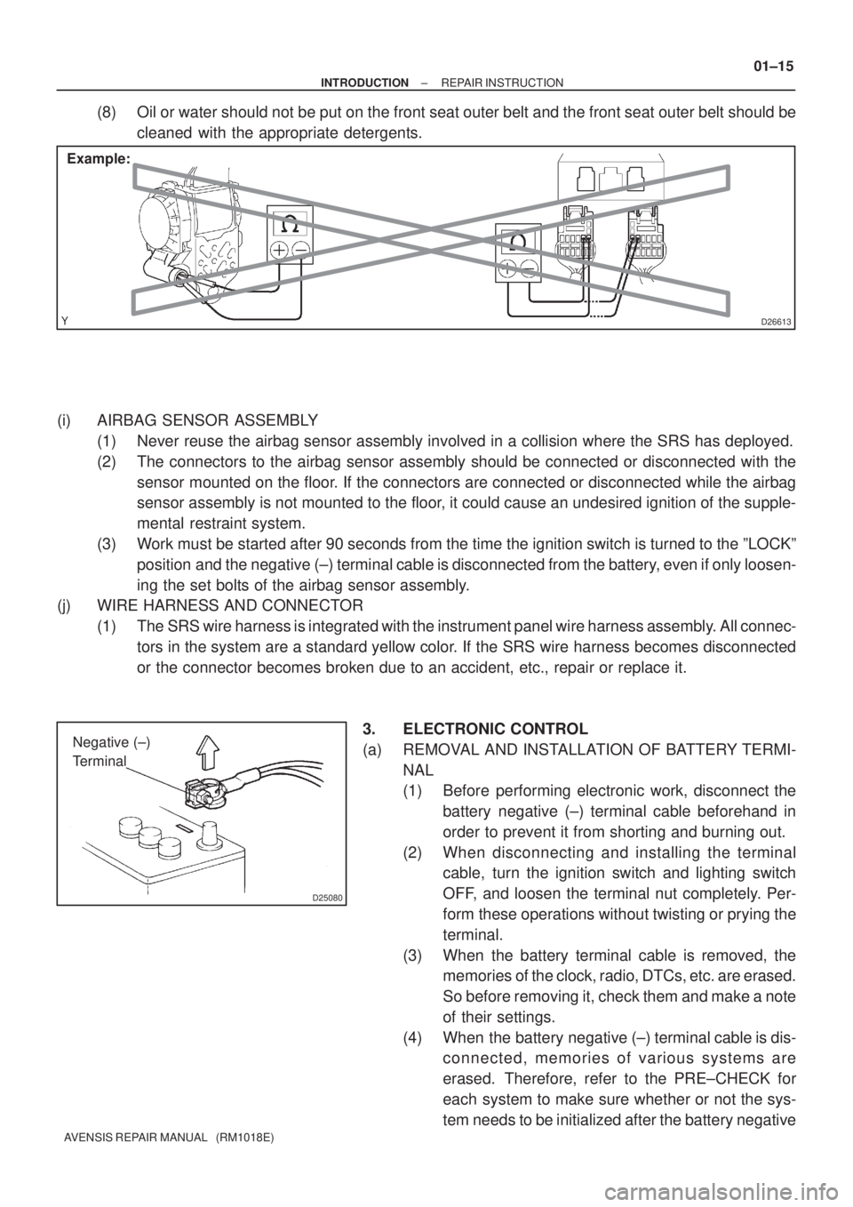
3. ELECTRONIC CONTROL
(a) REMOVAL AND INSTALLATION OF BATTERY TERMI-
NAL
(1) Before performing electronic work, disconnect the
battery negative (±) terminal cable beforehand in
order to prevent it from shorting and burning out.
(2) When disconnecting and installing the terminal
cable, turn the ignition switch and lighting switch
OFF, and loosen the terminal nut completely. Per-
form these operations without twisting or prying the
terminal.
(3) When the battery terminal cable is removed, the
memories of the clock, radio, DTCs, etc. are erased.
So before removing it, check them and make a note
of their settings.
(4) When the battery negative (±) terminal cable is dis-
connected, memories of various systems are
erased. Therefore, refer to the PRE±CHECK for
each system to make sure whether or not the sys-
tem needs to be initialized after the battery negative
Page 1014 of 1690
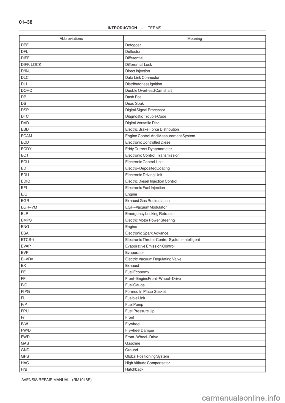
01±38
± INTRODUCTIONTERMS
AVENSIS REPAIR MANUAL (RM1018E)Abbreviations Meaning
DEFDefogger
DFLDeflector
DIFF.Differential
DIFF. LOCKDifferential Lock
D/INJDirect Injection
DLCData Link Connector
DLIDistributorless Ignition
DOHCDouble Overhead Camshaft
DPDash Pot
DSDead Soak
DSPDigital Signal Processor
DTCDiagnostic Trouble Code
DVDDigital Versatile Disc
EBDElectric Brake Force Distribution
ECAMEngine Control And Measurement System
ECDElectronic Controlled Diesel
ECDYEddy Current Dynamometer
ECTElectronic Control Transmission
ECUElectronic Control Unit
EDElectro±Deposited Coating
EDUElectronic Driving Unit
EDICElectric Diesel Injection Control
EFIElectronic Fuel Injection
E/GEngine
EGRExhaust Gas Recirculation
EGR±VMEGR±Vacuum Modulator
ELREmergency Locking Retractor
EMPSElectric Motor Power Steering
ENGEngine
ESAElectronic Spark Advance
ETCS±iElectronic Throttle Control System±intelligent
EVAPEvaporative Emission Control
EVPEvaporator
E±VRVElectric Vacuum Regulating Valve
EXExhaust
FEFuel Economy
FFFront±Engine Front±Wheel±Drive
F/GFuel Gauge
FIPGFormed In Place Gasket
FLFusible Link
F/PFuel Pump
FPUFuel Pressure Up
FrFront
F/WFlywheel
FW/DFlywheel Damper
FWDFront±Wheel±Drive
GASGasoline
GNDGround
GPSGlobal Positioning System
HACHigh Altitude Compensator
H/BHatchback