Page 398 of 1690
A77395
Engine
Front
A77396
Hook
Pin
Turn
Disconnect
A77397
Push
Turn
Plunger
A77398
A
B
A
A
± ENGINE MECHANICALCHAIN SUB±ASSY (1AZ±FE)
14±151
AVENSIS REPAIR MANUAL (RM1018E)
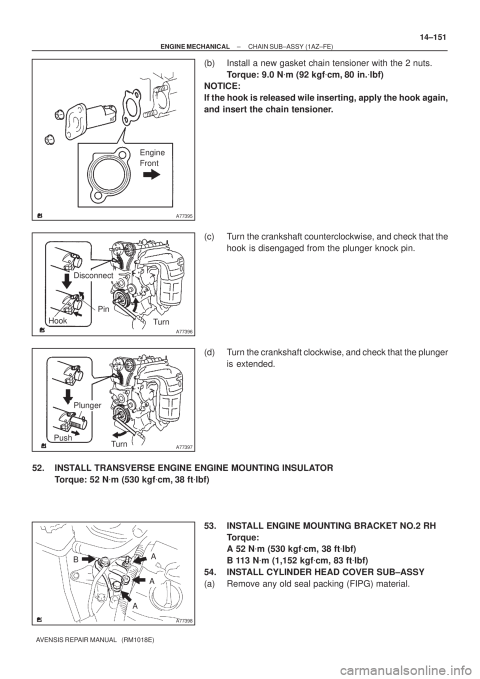
(b) Install a new gasket chain tensioner with the 2 nuts.
Torque: 9.0 N�m (92 kgf�cm, 80 in.�lbf)
NOTICE:
If the hook is released wile inserting, apply the hook again,
and insert the chain tensioner.
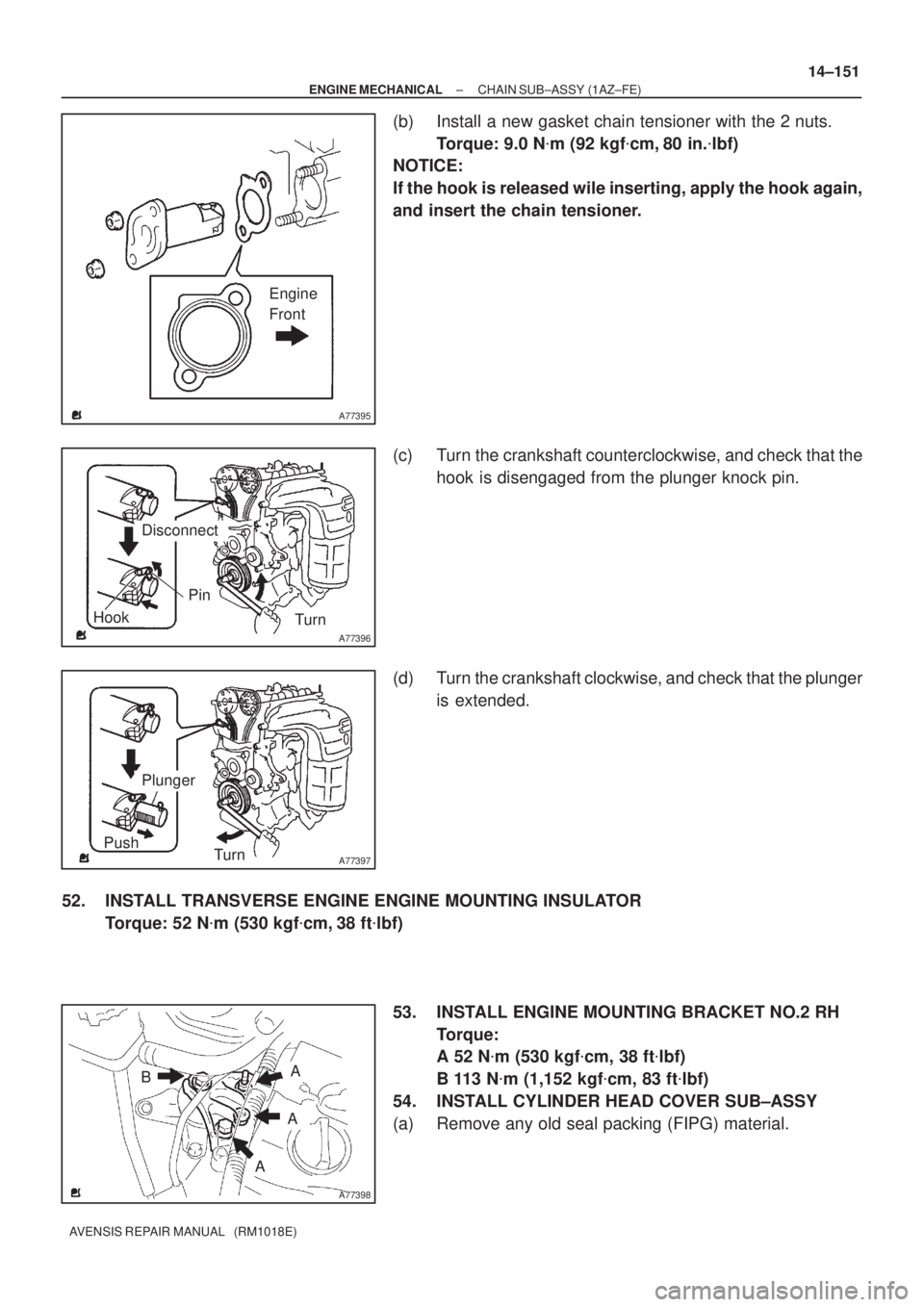
(c) Turn the crankshaft counterclockwise, and check that the
hook is disengaged from the plunger knock pin.
(d) Turn the crankshaft clockwise, and check that the plunger
is extended.
52. INSTALL TRANSVERSE ENGINE ENGINE MOUNTING INSULATOR
Torque: 52 N�m (530 kgf�cm, 38 ft�lbf)
53. INSTALL ENGINE MOUNTING BRACKET NO.2 RH
Torque:
A 52 N�m (530 kgf�cm, 38 ft�lbf)
B 113 N�m (1,152 kgf�cm, 83 ft�lbf)
54. INSTALL CYLINDER HEAD COVER SUB±ASSY
(a) Remove any old seal packing (FIPG) material.
Page 406 of 1690
A77382
Groove90�
A77383
Groove
A66833
B11424
± ENGINE MECHANICALCHAIN SUB±ASSY (1AZ±FE)
14±145
AVENSIS REPAIR MANUAL (RM1018E)
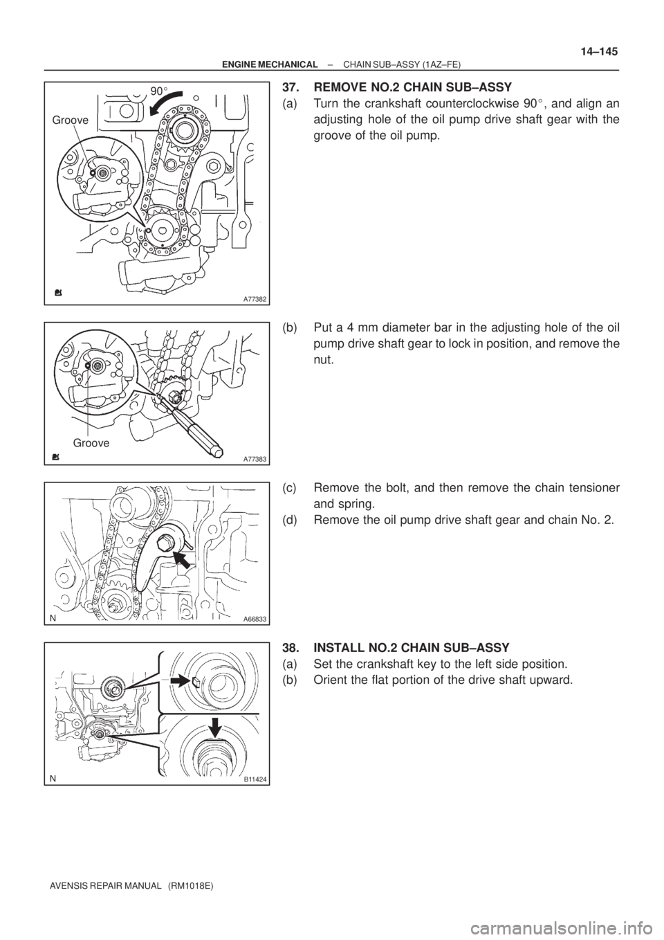
37. REMOVE NO.2 CHAIN SUB±ASSY
(a) Turn the crankshaft counterclockwise 90�, and align an
adjusting hole of the oil pump drive shaft gear with the
groove of the oil pump.
(b) Put a 4 mm diameter bar in the adjusting hole of the oil
pump drive shaft gear to lock in position, and remove the
nut.
(c) Remove the bolt, and then remove the chain tensioner
and spring.
(d) Remove the oil pump drive shaft gear and chain No. 2.
38. INSTALL NO.2 CHAIN SUB±ASSY
(a) Set the crankshaft key to the left side position.
(b) Orient the flat portion of the drive shaft upward.
Page 407 of 1690
A77384
Mark Link
Timing Mark
Timing Mark
Mark Link
A77385
Groove
A77386
Groove
A77387
90� 14±146
± ENGINE MECHANICALCHAIN SUB±ASSY (1AZ±FE)
AVENSIS REPAIR MANUAL (RM1018E)
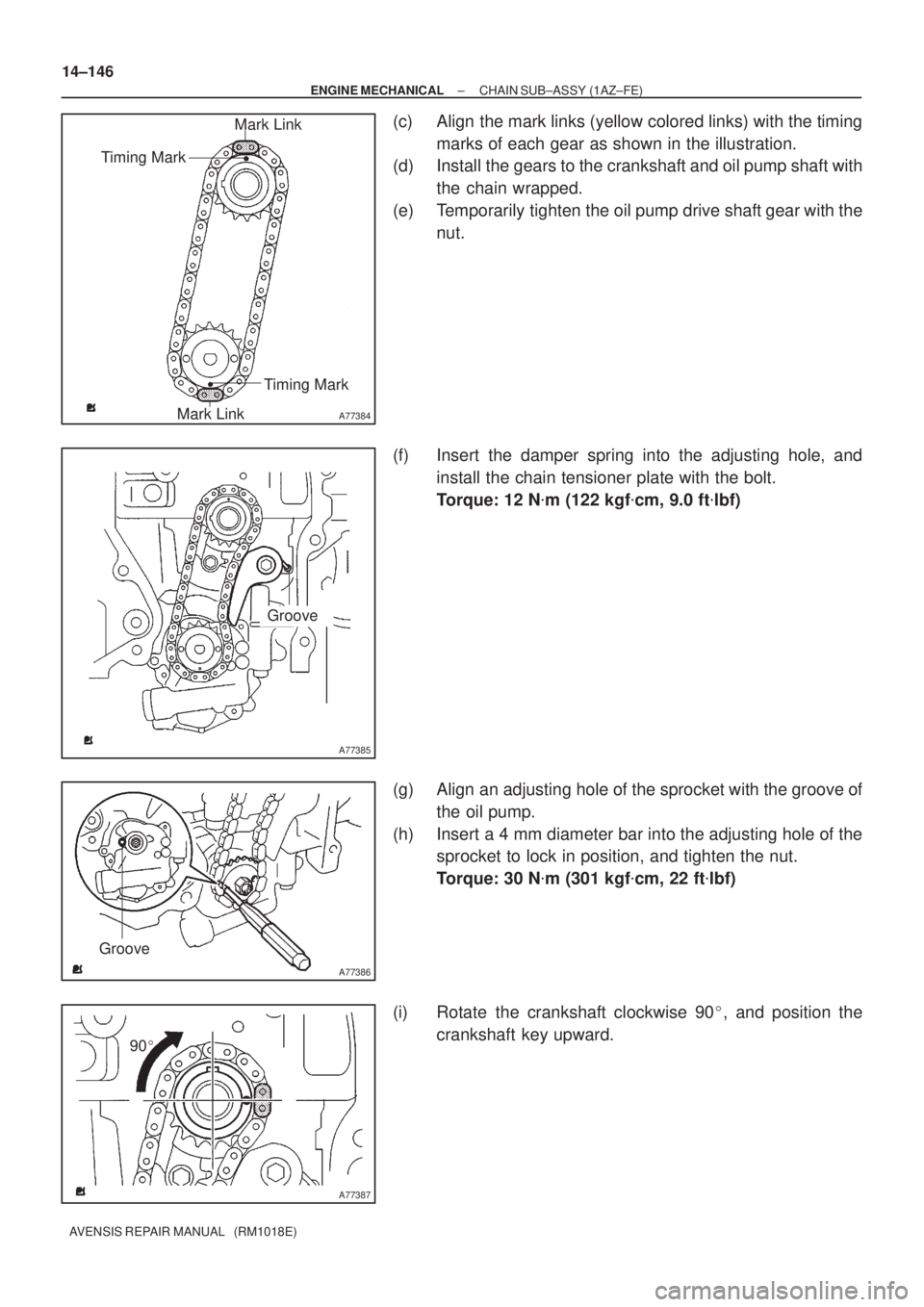
(c) Align the mark links (yellow colored links) with the timing
marks of each gear as shown in the illustration.
(d) Install the gears to the crankshaft and oil pump shaft with
the chain wrapped.
(e) Temporarily tighten the oil pump drive shaft gear with the
nut.
(f) Insert the damper spring into the adjusting hole, and
install the chain tensioner plate with the bolt.
Torque: 12 N�m (122 kgf�cm, 9.0 ft�lbf)
(g) Align an adjusting hole of the sprocket with the groove of
the oil pump.
(h) Insert a 4 mm diameter bar into the adjusting hole of the
sprocket to lock in position, and tighten the nut.
Torque: 30 N�m (301 kgf�cm, 22 ft�lbf)
(i) Rotate the crankshaft clockwise 90�, and position the
crankshaft key upward.
Page 412 of 1690
A77395
Engine
Front
A77396
Hook
Pin
Turn
Disconnect
A77397
Push
Turn
Plunger
A77398
A
B
A
A
± ENGINE MECHANICALCHAIN SUB±ASSY (1AZ±FE)
14±151
AVENSIS REPAIR MANUAL (RM1018E)
(b) Install a new gasket chain tensioner with the 2 nuts.
Torque: 9.0 N�m (92 kgf�cm, 80 in.�lbf)
NOTICE:
If the hook is released wile inserting, apply the hook again,
and insert the chain tensioner.
(c) Turn the crankshaft counterclockwise, and check that the
hook is disengaged from the plunger knock pin.
(d) Turn the crankshaft clockwise, and check that the plunger
is extended.
52. INSTALL TRANSVERSE ENGINE ENGINE MOUNTING INSULATOR
Torque: 52 N�m (530 kgf�cm, 38 ft�lbf)
53. INSTALL ENGINE MOUNTING BRACKET NO.2 RH
Torque:
A 52 N�m (530 kgf�cm, 38 ft�lbf)
B 113 N�m (1,152 kgf�cm, 83 ft�lbf)
54. INSTALL CYLINDER HEAD COVER SUB±ASSY
(a) Remove any old seal packing (FIPG) material.
Page 458 of 1690
A61194
Pry
A09555
Measuring Point
16 mm (0.63 in.)
A09569
Measuring Tip
Protrusion Hight
± ENGINE MECHANICALCYLINDER HEAD GASKET (1CD±FTV)
14±335
AVENSIS REPAIR MANUAL (RM1018E)
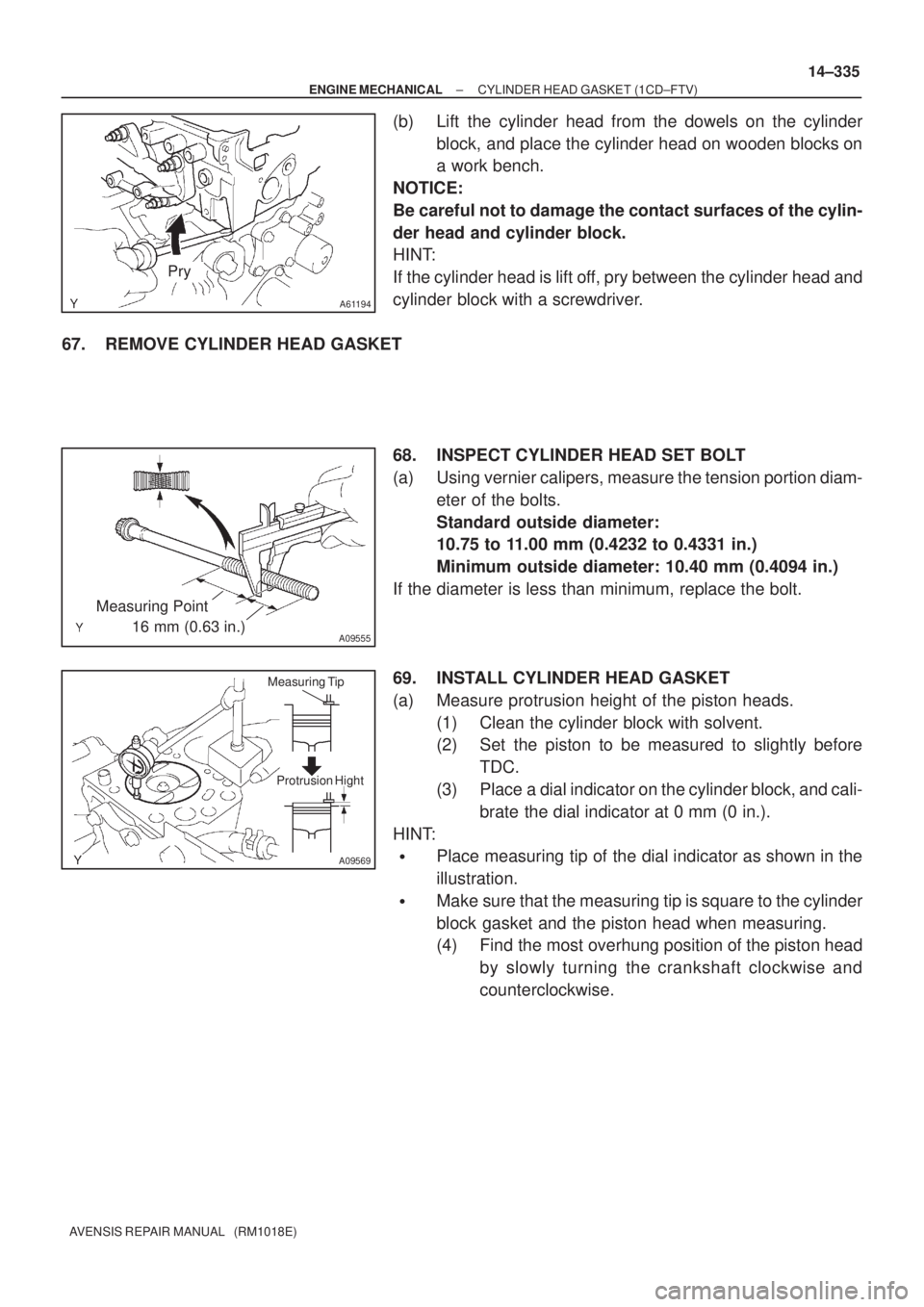
(b) Lift the cylinder head from the dowels on the cylinder
block, and place the cylinder head on wooden blocks on
a work bench.
NOTICE:
Be careful not to damage the contact surfaces of the cylin-
der head and cylinder block.
HINT:
If the cylinder head is lift off, pry between the cylinder head and
cylinder block with a screwdriver.
67. REMOVE CYLINDER HEAD GASKET
68. INSPECT CYLINDER HEAD SET BOLT
(a) Using vernier calipers, measure the tension portion diam-
eter of the bolts.
Standard outside diameter:
10.75 to 11.00 mm (0.4232 to 0.4331 in.)
Minimum outside diameter: 10.40 mm (0.4094 in.)
If the diameter is less than minimum, replace the bolt.
69. INSTALL CYLINDER HEAD GASKET
(a) Measure protrusion height of the piston heads.
(1) Clean the cylinder block with solvent.
(2) Set the piston to be measured to slightly before
TDC.
(3) Place a dial indicator on the cylinder block, and cali-
brate the dial indicator at 0 mm (0 in.).
HINT:
�Place measuring tip of the dial indicator as shown in the
illustration.
�Make sure that the measuring tip is square to the cylinder
block gasket and the piston head when measuring.
(4) Find the most overhung position of the piston head
by slowly turning the crankshaft clockwise and
counterclockwise.
Page 471 of 1690
A60622
A79324
A76713
A64023
14±82
±
ENGINE MECHANICAL CYLINDER HEAD GASKET(1ZZ±FE/3ZZ±FE)
AVENSIS REPAIR MANUAL (RM1018E)
14.DISCONNECT FUEL TUBE SUB±ASSY (See page 11±11) SST09268±21010
15.DISCONNECT UNION TO CONNECTOR TUBE HOSE
(a)Disconnect the union to connector tube hose from the hose to hose tube.
16.DISCONNECT RADIATOR HOSE INLET
(a)Disconnect radiator hose inlet from the cylinder head.
17.DISCONNECT HEATER INLET WATER HOSE
(a)Disconnect the heater inlet water hose from the cylinder head.
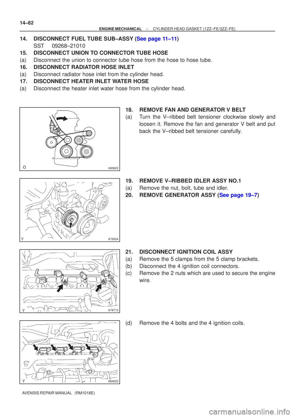
18.REMOVE FAN AND GENERATOR V BELT
(a)Turn the V±ribbed belt tensioner clockwise slowly andloosen it. Remove the fan and generator V belt and put
back the V±ribbed belt tensioner carefully.
19.REMOVE V±RIBBED IDLER ASSY NO.1
(a)Remove the nut, bolt, tube and idler.
20.REMOVE GENERATOR ASSY (See page 19±7)
21. DISCONNECT IGNITION COIL ASSY
(a) Remove the 5 clamps from the 5 clamp brackets.
(b) Disconnect the 4 ignition coil connectors.
(c) Remove the 2 nuts which are used to secure the engine wire.
(d) Remove the 4 bolts and the 4 ignition coils.
Page 476 of 1690
A30857
A62814
4 2531
A62816
2
5 3
110 8 4 796
A62827
Lot No.
A62820
Overall Length
± ENGINE MECHANICALCYLINDER HEAD GASKET (1ZZ±FE/3ZZ±FE)
14±87
AVENSIS REPAIR MANUAL (RM1018E)
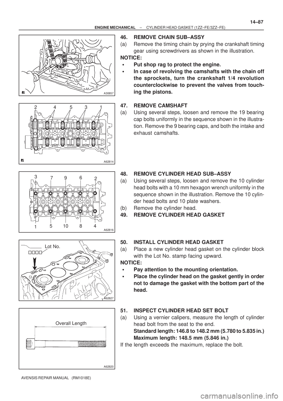
46. REMOVE CHAIN SUB±ASSY
(a) Remove the timing chain by prying the crankshaft timing
gear using screwdrivers as shown in the illustration.
NOTICE:
�Put shop rag to protect the engine.
�In case of revolving the camshafts with the chain off
the sprockets, turn the crankshaft 1/4 revolution
counterclockwise to prevent the valves from touch-
ing the pistons.
47. REMOVE CAMSHAFT
(a) Using several steps, loosen and remove the 19 bearing
cap bolts uniformly in the sequence shown in the illustra-
tion. Remove the 9 bearing caps, and both the intake and
exhaust camshafts.
48. REMOVE CYLINDER HEAD SUB±ASSY
(a) Using several steps, loosen and remove the 10 cylinder
head bolts with a 10 mm hexagon wrench uniformly in the
sequence shown in the illustration. Remove the 10 cylin-
der head bolts and 10 plate washers.
(b) Remove the cylinder head.
49. REMOVE CYLINDER HEAD GASKET
50. INSTALL CYLINDER HEAD GASKET
(a) Place a new cylinder head gasket on the cylinder block
with the Lot No. stamp facing upward.
NOTICE:
�Pay attention to the mounting orientation.
�Place the cylinder head on the gasket gently in order
not to damage the gasket with the bottom part of the
head.
51. INSPECT CYLINDER HEAD SET BOLT
(a) Using a vernier calipers, measure the length of cylinder
head bolt from the seat to the end.
Standard length: 146.8 to 148.2 mm (5.780 to 5.835 in.)
Maximum length: 148.5 mm (5.846 in.)
If the length exceeds the maximum, replace the bolt.
Page 481 of 1690
A12816
A11858
A62837SST
A62180
DisconnectHook
PinTurn
A62181
Plunger
Turn
Push
14±92
±
ENGINE MECHANICAL CYLINDER HEAD GASKET(1ZZ±FE/3ZZ±FE)
AVENSIS REPAIR MANUAL (RM1018E)
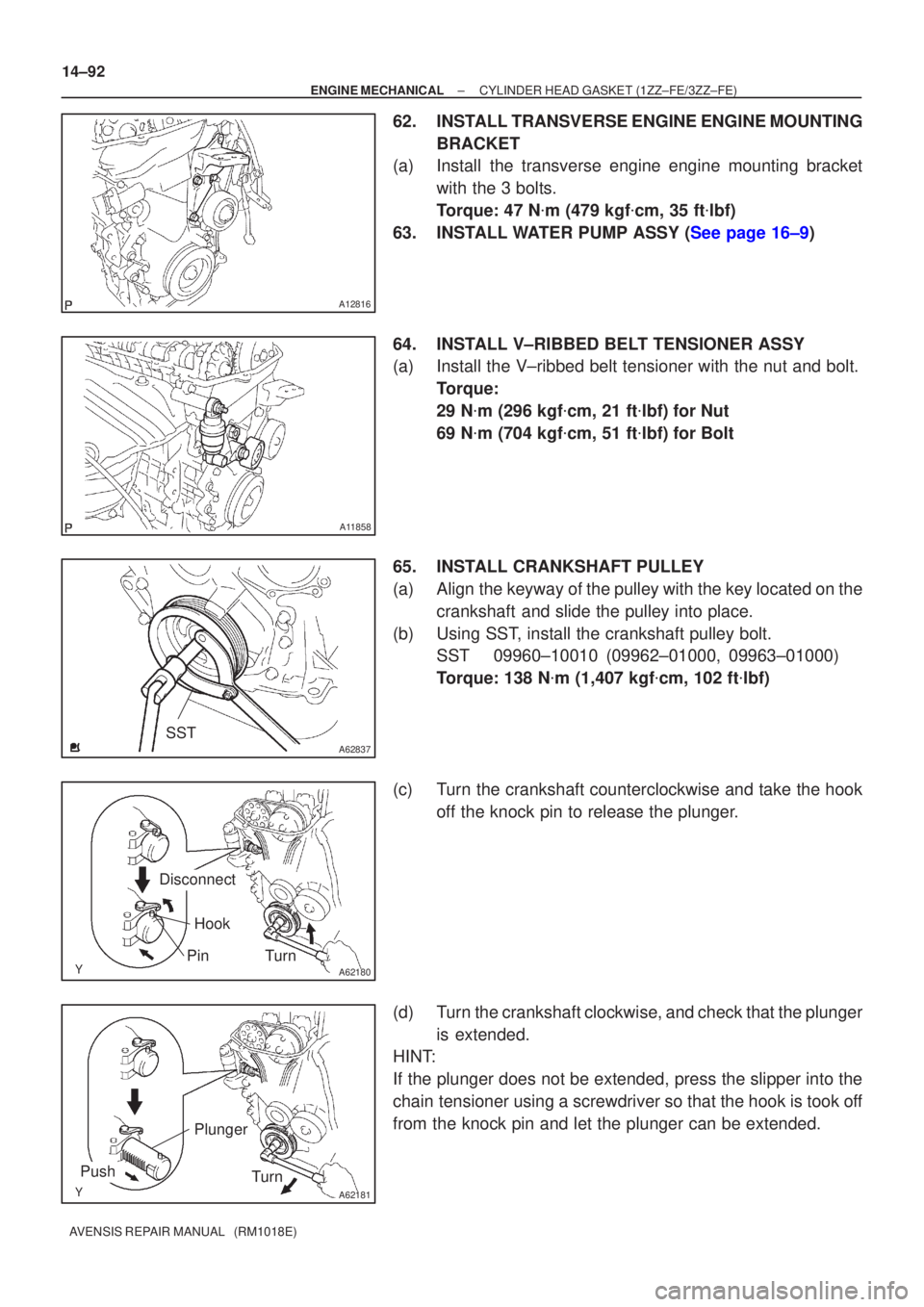
62.INSTALL TRANSVERSE ENGINE ENGINE MOUNTING BRACKET
(a)Install the transverse engine engine mounting bracket
with the 3 bolts.
Torque: 47 N �m (479 kgf �cm, 35 ft �lbf)
63.INSTALL WATER PUMP ASSY (See page 16±9)
64. INSTALL V±RIBBED BELT TENSIONER ASSY
(a) Install the V±ribbed belt tensioner with the nut and bolt. Torque:
29 N�m (296 kgf �cm, 21 ft �lbf) for Nut
69 N �m (704 kgf �cm, 51 ft �lbf) for Bolt
65. INSTALL CRANKSHAFT PULLEY
(a) Align the keyway of the pulley with the key located on the crankshaft and slide the pulley into place.
(b) Using SST, install the crankshaft pulley bolt. SST 09960±10010 (09962±01000, 09963±01000)
Torque: 138 N �m (1,407 kgf �cm, 102 ft �lbf)
(c) Turn the crankshaft counterclockwise and take the hook off the knock pin to release the plunger.
(d) Turn the crankshaft clockwise, and check that the plunger is extended.
HINT:
If the plunger does not be extended, press the slipper into the
chain tensioner using a screwdriver so that the hook is took off
from the knock pin and let the plunger can be extended.