Page 485 of 1690
141C1±01
A56434
AB
A56462
A56434
AB
±
ENGINE MECHANICAL DRIVE BELT(1CD±FTV)
14±269
AVENSIS REPAIR MANUAL (RM1018E)
DRIVE BELT(1CD±FTV)
REPLACEMENT
1.REMOVE RADIATOR SUPPORT OPENING COVER
2.REMOVE ENGINE ROOM COVER SIDE
3.REMOVE ENGINE UNDER COVER RH
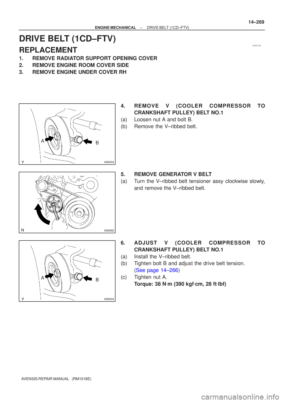
4.REMOVE V (COOLER CO MPRESSOR TO
CRANKSHAFT PULLEY) BELT NO.1
(a)Loosen nut A and bolt B.
(b)Remove the V±ribbed belt.
5.REMOVE GENERATOR V BELT
(a)Turn the V±ribbed belt tensioner assy clockwise slowly, and remove the V±ribbed belt.
6.ADJUS T V (COOLER CO MPRESSOR TO
CRANKSHAFT PULLEY) BELT NO.1
(a)Install the V±ribbed belt.
(b)Tighten bolt B and adjust the drive belt tension. (See page 14±266)
(c) Tighten nut A. Torque: 38 N �m (390 kgf �cm, 28 ft �lbf)
Page 508 of 1690
141B5±01
A77293
SST
± ENGINE MECHANICALFAN AND GENERATOR V BELT (1AZ±FE)
14±105
AVENSIS REPAIR MANUAL (RM1018E)
FAN AND GENERATOR V BELT (1AZ±FE)
REPLACEMENT
1. REMOVE RADIATOR SUPPORT OPENING COVER
2. REMOVE ENGINE ROOM COVER SIDE
3. REMOVE ENGINE UNDER COVER RH
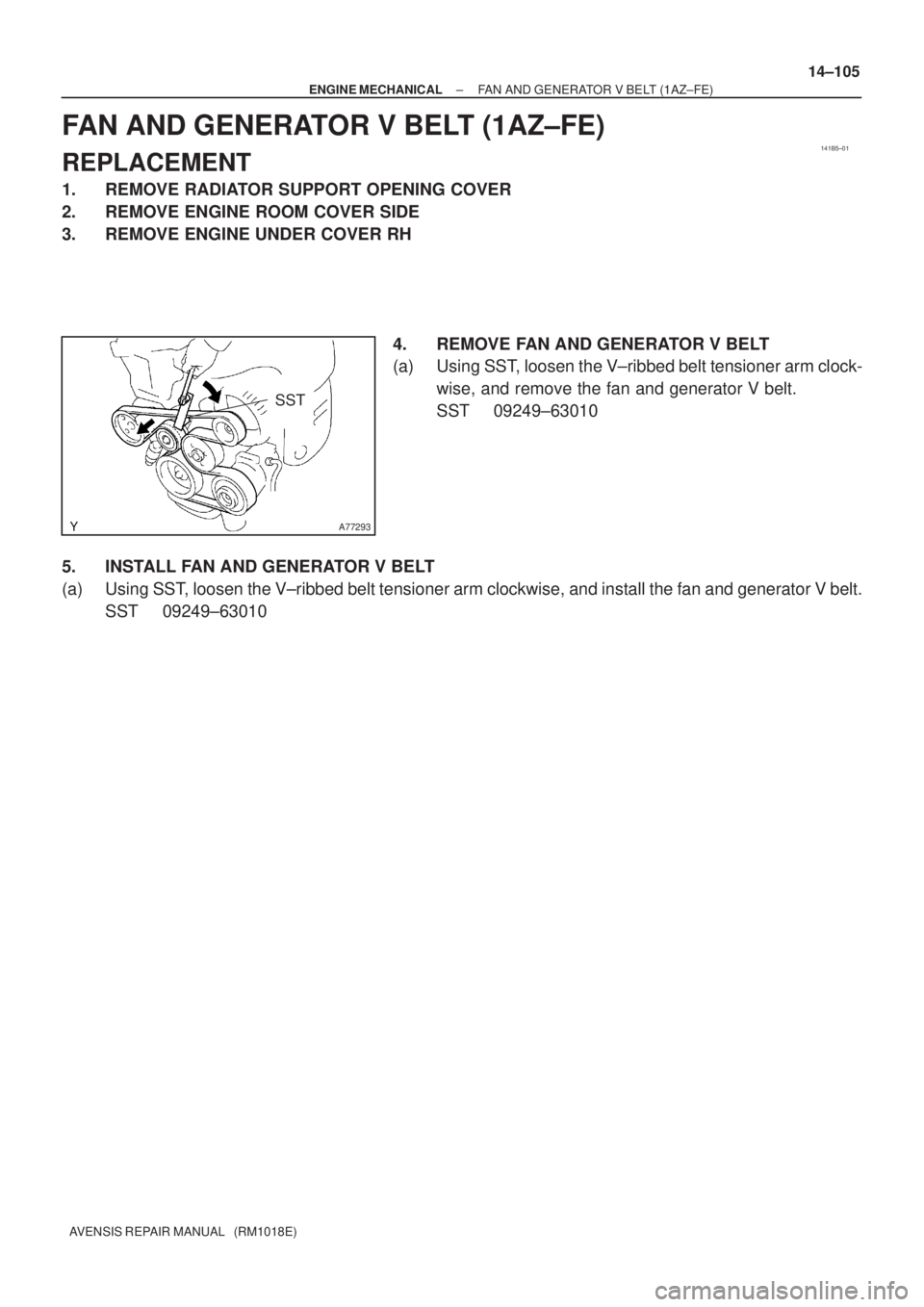
4. REMOVE FAN AND GENERATOR V BELT
(a) Using SST, loosen the V±ribbed belt tensioner arm clock-
wise, and remove the fan and generator V belt.
SST 09249±63010
5. INSTALL FAN AND GENERATOR V BELT
(a) Using SST, loosen the V±ribbed belt tensioner arm clockwise, and install the fan and generator V belt.
SST 09249±63010
Page 509 of 1690
141BJ±01
A77423
SST
± ENGINE MECHANICALFAN AND GENERATOR V BELT (1AZ±FSE)
14±185
AVENSIS REPAIR MANUAL (RM1018E)
FAN AND GENERATOR V BELT (1AZ±FSE)
REPLACEMENT
1. REMOVE RADIATOR SUPPORT OPENING COVER
2. REMOVE ENGINE ROOM COVER SIDE
3. REMOVE ENGINE UNDER COVER RH
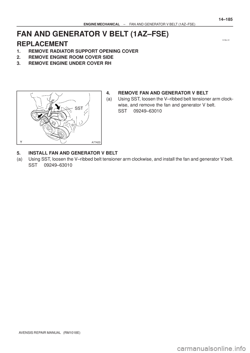
4. REMOVE FAN AND GENERATOR V BELT
(a) Using SST, loosen the V±ribbed belt tensioner arm clock-
wise, and remove the fan and generator V belt.
SST 09249±63010
5. INSTALL FAN AND GENERATOR V BELT
(a) Using SST, loosen the V±ribbed belt tensioner arm clockwise, and install the fan and generator V belt.
SST 09249±63010
Page 510 of 1690
141CD±01
A60622
±
ENGINE MECHANICAL FAN AND GENERATOR V BELT(1ZZ±FE/3ZZ±FE)
14±5
AVENSIS REPAIR MANUAL (RM1018E)
FAN AND GENERATOR V BELT(1ZZ±FE/3ZZ±FE)
REPLACEMENT
1.REMOVE RADIATOR SUPPORT OPENING COVER (See page 14±27)
2.REMOVE ENGINE ROOM COVER SIDE (See page 14±27)
3.REMOVE ENGINE UNDER COVER SUB±ASSY NO.1 (See page 14±27)
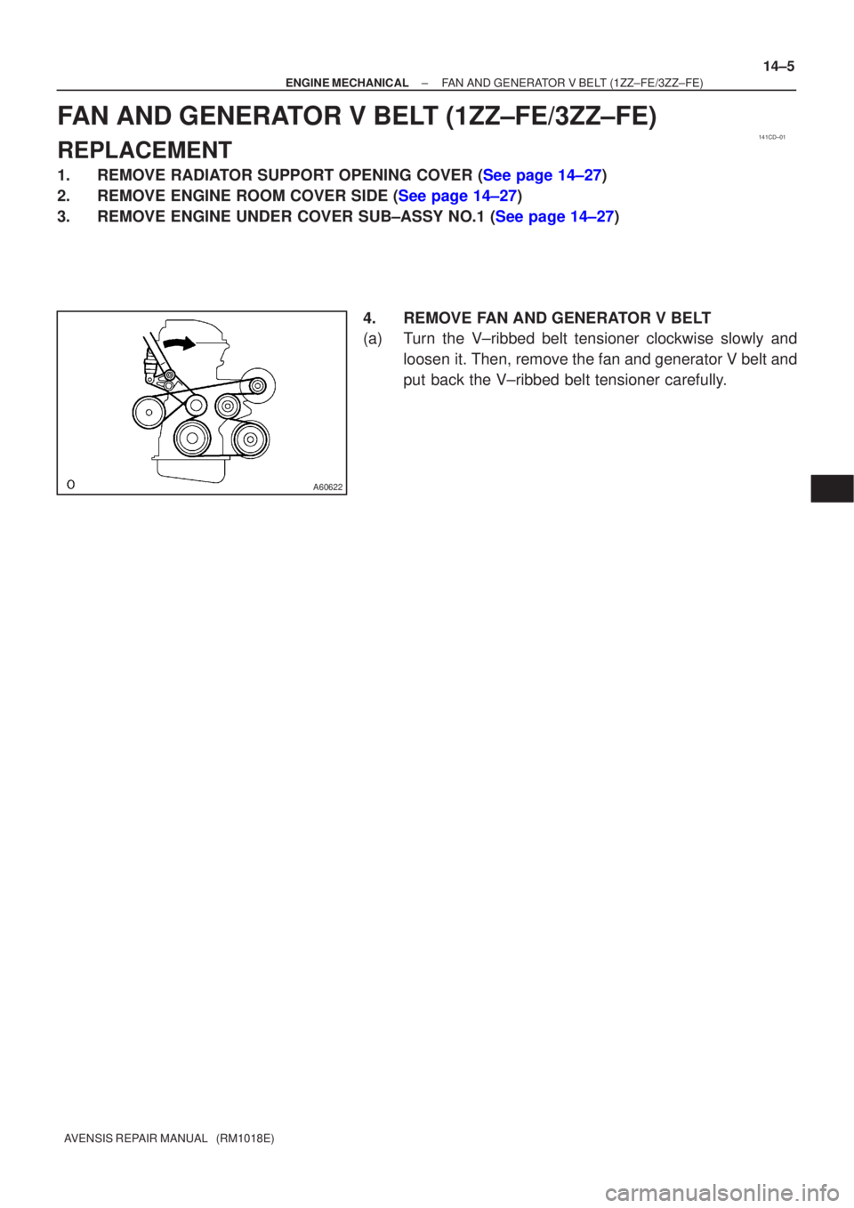
4. REMOVE FAN AND GENERATOR V BELT
(a) Turn the V±ribbed belt tensioner clockwise slowly andloosen it. Then, remove the fan and generator V belt and
put back the V±ribbed belt tensioner carefully.
Page 574 of 1690
A77338
A79320
A79296
A60622
14±30
±
ENGINE MECHANICAL PARTIAL ENGINE ASSY (1ZZ±FE/3ZZ±FE)
AVENSIS REPAIR MANUAL (RM1018E)
32. SEPARATE FLOOR SHIFT CABLE TRANSMISSION CONTROL SELECT (M/T TRANSAXLE) (See page 41±15)
33. SEPARATE FLOOR SHIFT CABLE TRANSMISSION CONTROL SHIFT (M/T TRANSAXLE)
(See page 41±15)
34. SEPARATE FLOOR SHIFT CABLE TRANSMISSION CONTROL SHIFT (A/T TRANSAXLE) (See page 40±11)
35.SEPARATE CLUTCH RELEASE CYLINDER ASSY (M/T TRANSAXLE) (See page 41±15)
36.REMOVE GLOVE COMPARTMENT DOOR ASSY (See page 71±11)
37. REMOVE INSTRUMENT PANEL UNDER COVER SUB±ASSY NO.2
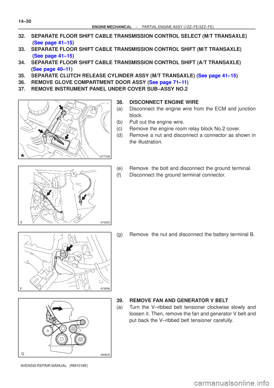
38. DISCONNECT ENGINE WIRE
(a) Disconnect the engine wire from the ECM and junctionblock.
(b) Pull out the engine wire.
(c) Remove the engine room relay block No.2 cover.
(d) Remove a nut and disconnect a connector as shown in the illustration.
(e) Remove the bolt and disconnect the ground terminal.
(f) Disconnect the ground terminal connector.
(g) Remove the nut and disconnect the battery terminal B.
39. REMOVE FAN AND GENERATOR V BELT
(a) Turn the V±ribbed belt tensioner clockwise slowly and loosen it. Then, remove the fan and generator V belt and
put back the V±ribbed belt tensioner carefully.
Page 594 of 1690
A09612
1st
2nd 5th
3rd
4th 6th 7th
A09589
Hexagon
Wrench
(1.27 mm)
(A)
A09623
A61179
Hexagon
Wrench
(1.27 mm)
A09605
Turn
Dot Mark
TDC Mark
14±310
± ENGINE MECHANICALTIMING BELT (1CD±FTV)
AVENSIS REPAIR MANUAL (RM1018E)
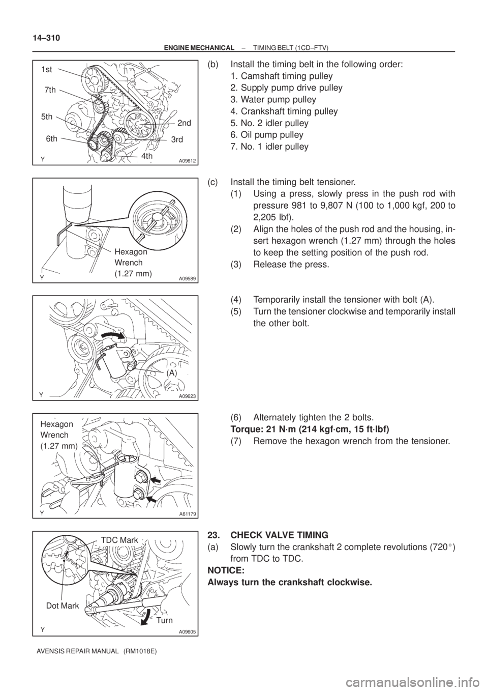
(b) Install the timing belt in the following order:
1. Camshaft timing pulley
2. Supply pump drive pulley
3. Water pump pulley
4. Crankshaft timing pulley
5. No. 2 idler pulley
6. Oil pump pulley
7. No. 1 idler pulley
(c) Install the timing belt tensioner.
(1) Using a press, slowly press in the push rod with
pressure 981 to 9,807 N (100 to 1,000 kgf, 200 to
2,205 lbf).
(2) Align the holes of the push rod and the housing, in-
sert hexagon wrench (1.27 mm) through the holes
to keep the setting position of the push rod.
(3) Release the press.
(4) Temporarily install the tensioner with bolt (A).
(5) Turn the tensioner clockwise and temporarily install
the other bolt.
(6) Alternately tighten the 2 bolts.
Torque: 21 N´m (214 kgf´cm, 15 ft´lbf)
(7) Remove the hexagon wrench from the tensioner.
23. CHECK VALVE TIMING
(a) Slowly turn the crankshaft 2 complete revolutions (720�)
from TDC to TDC.
NOTICE:
Always turn the crankshaft clockwise.
Page 598 of 1690
141CN±01
A60622
A01045
A64005
A62837SST
14±96±
ENGINE MECHANICAL TIMING CHAIN OR BELT COVER OIL
SEAL(1ZZ±FE/3ZZ±FE)
AVENSIS REPAIR MANUAL (RM1018E)
TIMING GEAR COVER OIL SEAL(1ZZ±FE/3ZZ±FE)
REPLACEMENT
1.REMOVE FRONT WHEEL RH (See page 14±27)
2.REMOVE ENGINE UNDER COVER SUB±ASSY NO.1 (See page 14±27)
3.REMOVE ENGINE UNDER COVER RH (See page 14±27)
4.REMOVE RADIATOR SUPPORT OPENING COVER (See page 14±27)
5.REMOVE ENGINE ROOM COVER SIDE (See page 14±27) 6. REMOVE FAN AND GENERATOR V BELT
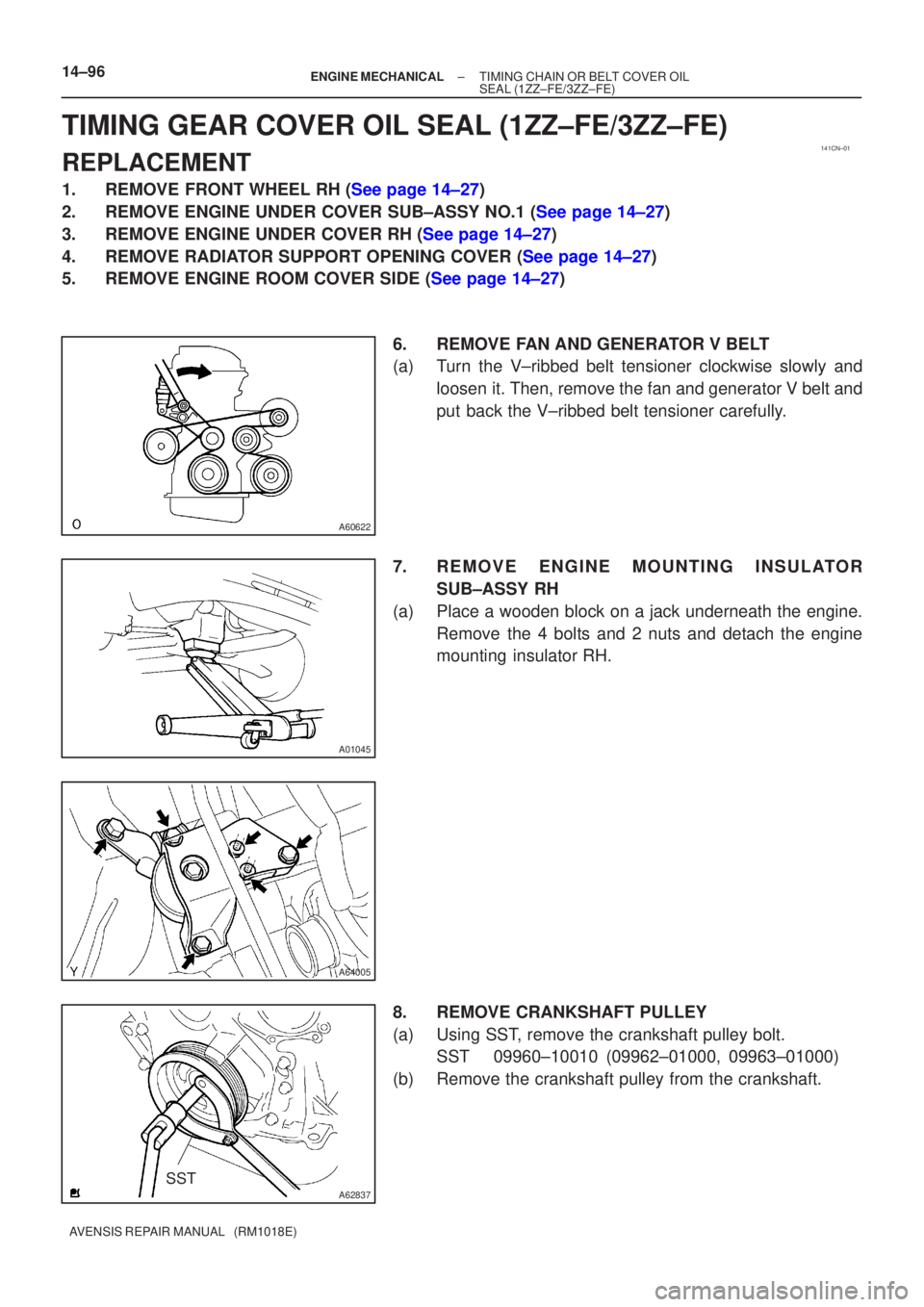
(a) Turn the V±ribbed belt tensioner clockwise slowly andloosen it. Then, remove the fan and generator V belt and
put back the V±ribbed belt tensioner carefully.
7. REMOVE ENGINE MOUNTING INSULATOR SUB±ASSY RH
(a) Place a wooden block on a jack underneath the engine. Remove the 4 bolts and 2 nuts and detach the engine
mounting insulator RH.
8. REMOVE CRANKSHAFT PULLEY
(a) Using SST, remove the crankshaft pulley bolt. SST 09960±10010 (09962±01000, 09963±01000)
(b) Remove the crankshaft pulley from the crankshaft.
Page 604 of 1690
141B6±01
A77281
A77378
No. 1 Cylinder TDC/Compression
IN
EX
A77379
No. 4 Cylinder TDC/Compression
IN
EX
14±106
±
ENGINE MECHANICAL VALVE CLEARANCE(1AZ±FE)
AVENSIS REPAIR MANUAL (RM1018E)
VALVE CLEARANCE(1AZ±FE)
ADJUSTMENT
1.REMOVE RADIATOR SUPPORT OPENING COVER
2.REMOVE ENGINE ROOM COVER SIDE
3.REMOVE ENGINE UNDER COVER RH 4.REMOVE ENGINE COVER SUB±ASSY NO.1
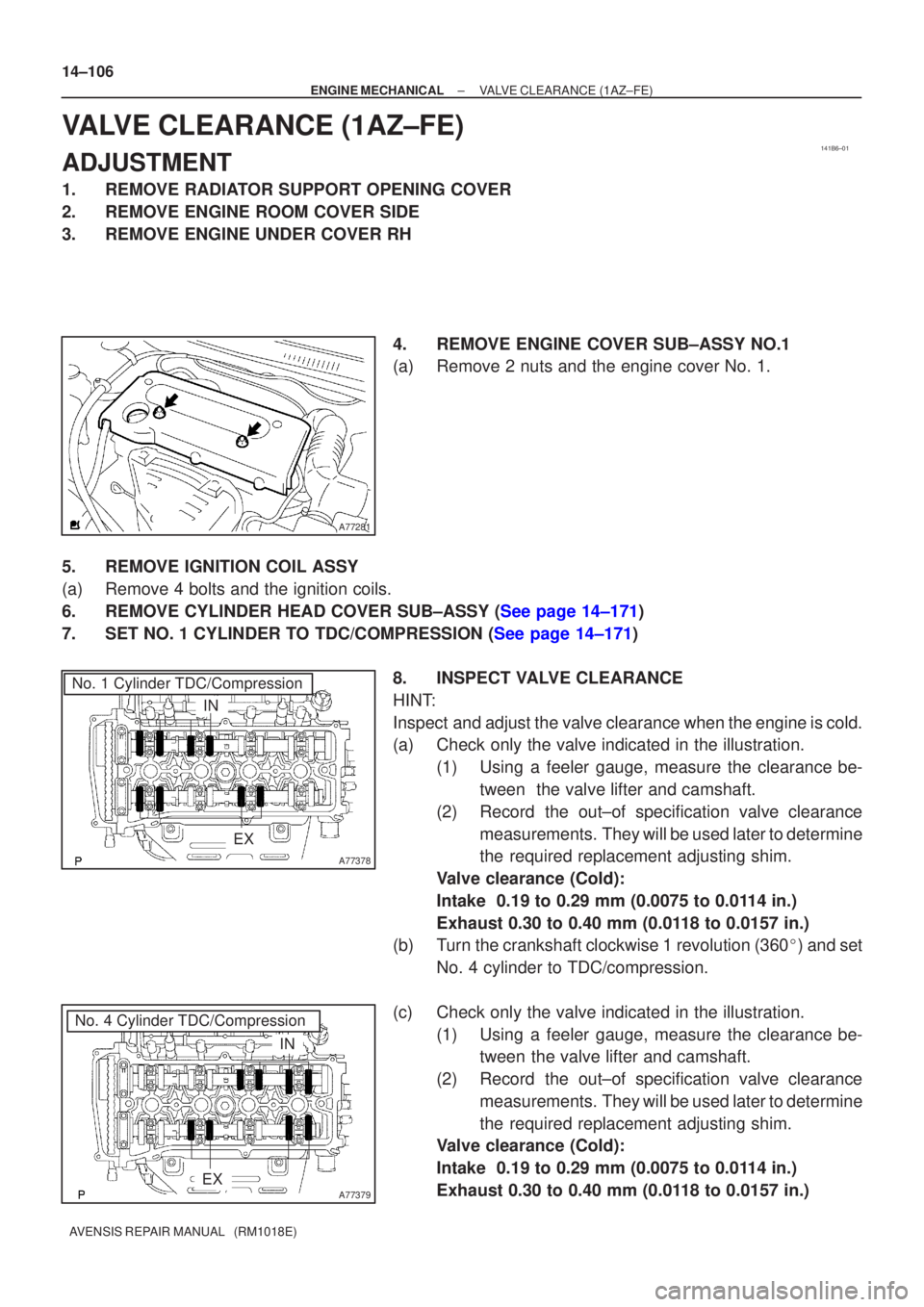
(a)Remove 2 nuts and the engine cover No. 1.
5.REMOVE IGNITION COIL ASSY
(a)Remove 4 bolts and the ignition coils.
6.REMOVE CYLINDER HEAD COVER SUB±ASSY (See page 14±171)
7.SET NO. 1 CYLINDER TO TDC/COMPRESSION (See page 14±171) 8. INSPECT VALVE CLEARANCE
HINT:
Inspect and adjust the valve clearance when the engine is cold.
(a) Check only the valve indicated in the illustration.(1) Using a feeler gauge, measure the clearance be-tween the valve lifter and camshaft.
(2) Record the out±of specification valve clearance measurements. They will be used later to determine
the required replacement adjusting shim.
Valve clearance (Cold):
Intake 0.19 to 0.29 mm (0.0075 to 0.0114 in.)
Exhaust 0.30 to 0.40 mm (0.0118 to 0.0157 in.)
(b) Turn the crankshaft clockwise 1 revolution (360 �) and set
No. 4 cylinder to TDC/compression.
(c) Check only the valve indicated in the illustration. (1) Using a feeler gauge, measure the clearance be-tween the valve lifter and camshaft.
(2) Record the out±of specification valve clearance measurements. They will be used later to determine
the required replacement adjusting shim.
Valve clearance (Cold):
Intake 0.19 to 0.29 mm (0.0075 to 0.0114 in.)
Exhaust 0.30 to 0.40 mm (0.0118 to 0.0157 in.)