2002 NISSAN TERRANO Fuel system
[x] Cancel search: Fuel systemPage 675 of 1767
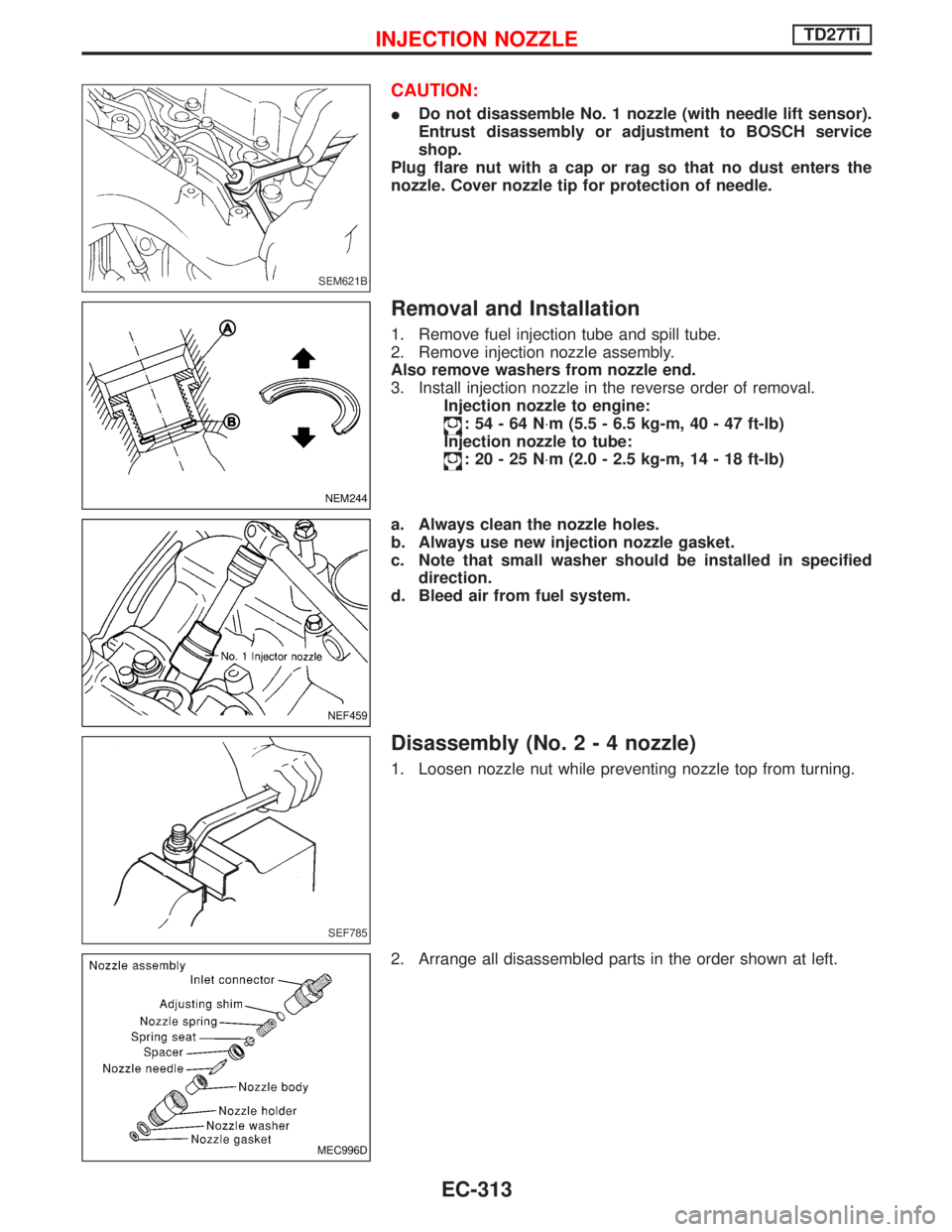
CAUTION:
IDo not disassemble No. 1 nozzle (with needle lift sensor).
Entrust disassembly or adjustment to BOSCH service
shop.
Plug flare nut with a cap or rag so that no dust enters the
nozzle. Cover nozzle tip for protection of needle.
Removal and Installation
1. Remove fuel injection tube and spill tube.
2. Remove injection nozzle assembly.
Also remove washers from nozzle end.
3. Install injection nozzle in the reverse order of removal.
Injection nozzle to engine:
:54-64N×m (5.5 - 6.5 kg-m, 40 - 47 ft-lb)
Injection nozzle to tube:
:20-25N×m (2.0 - 2.5 kg-m, 14 - 18 ft-lb)
a. Always clean the nozzle holes.
b. Always use new injection nozzle gasket.
c. Note that small washer should be installed in specified
direction.
d. Bleed air from fuel system.
Disassembly (No.2-4nozzle)
1. Loosen nozzle nut while preventing nozzle top from turning.
2. Arrange all disassembled parts in the order shown at left.
SEM621B
NEM244
NEF459
SEF785
MEC996D
INJECTION NOZZLETD27Ti
EC-313
Page 684 of 1767
How to Erase DTC (Without CONSULT-II)
1. If the ignition switch stays ªONº after repair work, be sure to turn ignition switch ªOFFº once. Wait at least
5 seconds and then turn it ªONº (engine stopped) again.
2. Change the diagnostic test mode from Mode II to Mode I by using the data link connector. (See EC-323.)
The emission related diagnostic information in the ECM can be erased by changing the diagnostic test mode.
IIf the battery is disconnected, the emission-related diagnostic information will be lost after approx.
24 hours.
IErasing the emission-related diagnostic information using CONSULT-II is easier and quicker than
switching the diagnostic test mode using the data link connector.
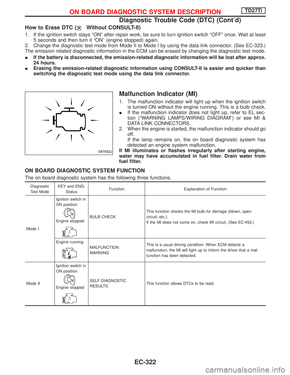
Malfunction Indicator (MI)
1. The malfunction indicator will light up when the ignition switch
is turned ON without the engine running. This is a bulb check.
IIf the malfunction indicator does not light up, refer to EL sec-
tion (ªWARNING LAMPS/WIRING DIAGRAMº) or see MI &
DATA LINK CONNECTORS.
2. When the engine is started, the malfunction indicator should go
off.
If the lamp remains on, the on board diagnostic system has
detected an engine system malfunction.
If MI illuminates or flashes irregularly after starting engine,
water may have accumulated in fuel filter. Drain water from
fuel filter.
ON BOARD DIAGNOSTIC SYSTEM FUNCTION
The on board diagnostic system has the following three functions.
Diagnostic
Test ModeKEY and ENG.
StatusFunction Explanation of Function
Mode IIgnition switch in
ON position
Engine stoppedBULB CHECKThis function checks the MI bulb for damage (blown, open
circuit, etc.).
If the MI does not come on, check MI circuit. (See EC-452.)
Engine running
MALFUNCTION
WARNINGThis is a usual driving condition. When ECM detects a
malfunction, the MI will light up to inform the driver that a mal-
function has been detected.
Mode IIIgnition switch in
ON position
Engine stopped
SELF-DIAGNOSTIC
RESULTSThis function allows DTCs to be read.
SAT652J
ON BOARD DIAGNOSTIC SYSTEM DESCRIPTIONTD27Ti
Diagnostic Trouble Code (DTC) (Cont'd)
EC-322
Page 690 of 1767
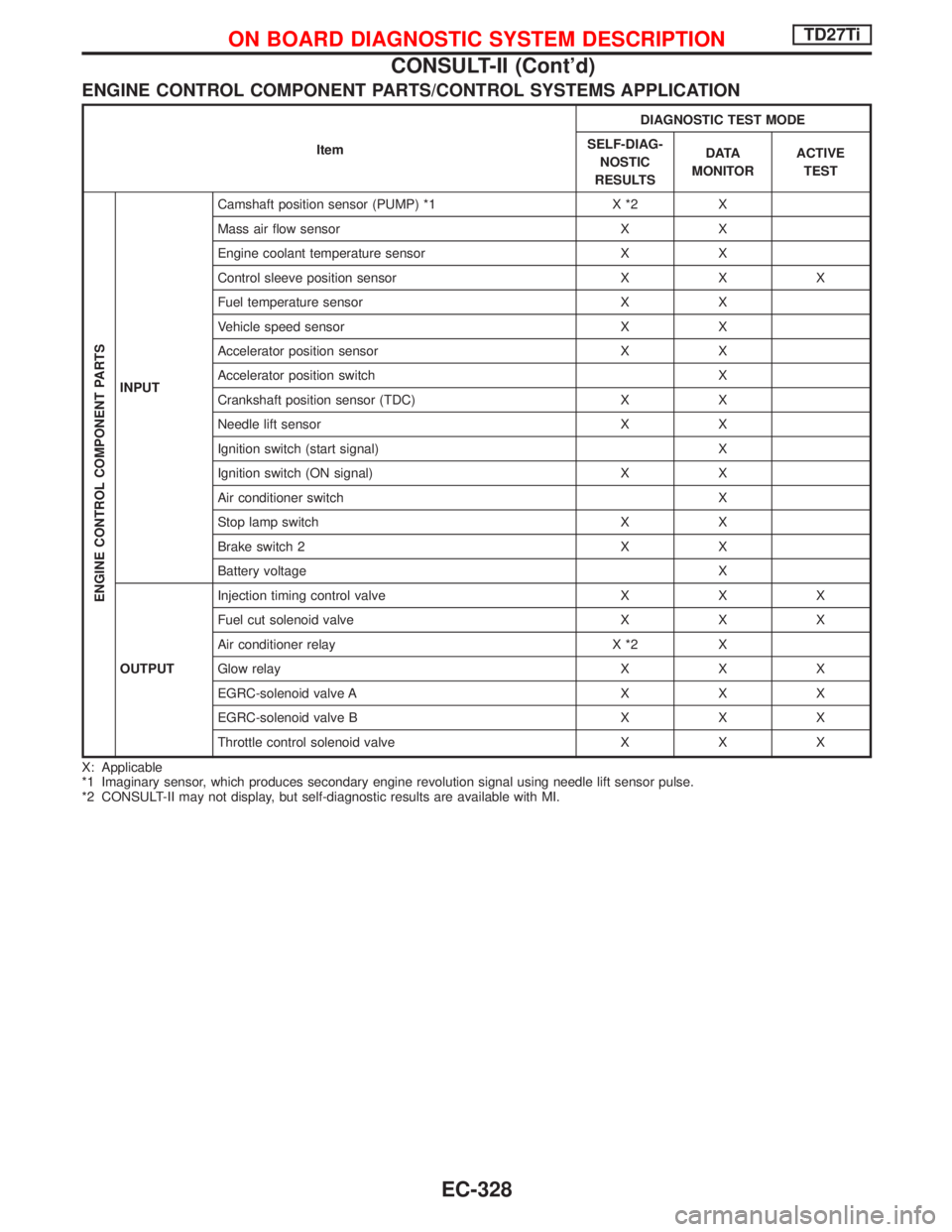
ENGINE CONTROL COMPONENT PARTS/CONTROL SYSTEMS APPLICATION
ItemDIAGNOSTIC TEST MODE
SELF-DIAG-
NOSTIC
RESULTSD ATA
MONITORACTIVE
TEST
ENGINE CONTROL COMPONENT PARTS
INPUTCamshaft position sensor (PUMP) *1 X *2 X
Mass air flow sensor X X
Engine coolant temperature sensor X X
Control sleeve position sensor X X X
Fuel temperature sensor X X
Vehicle speed sensor X X
Accelerator position sensor X X
Accelerator position switch X
Crankshaft position sensor (TDC) X X
Needle lift sensor X X
Ignition switch (start signal) X
Ignition switch (ON signal) X X
Air conditioner switch X
Stop lamp switch X X
Brake switch 2 X X
Battery voltage X
OUTPUTInjection timing control valve X X X
Fuel cut solenoid valve X X X
Air conditioner relay X *2 X
Glow relay X X X
EGRC-solenoid valve A X X X
EGRC-solenoid valve B X X X
Throttle control solenoid valve X X X
X: Applicable
*1 Imaginary sensor, which produces secondary engine revolution signal using needle lift sensor pulse.
*2 CONSULT-II may not display, but self-diagnostic results are available with MI.
ON BOARD DIAGNOSTIC SYSTEM DESCRIPTIONTD27Ti
CONSULT-II (Cont'd)
EC-328
Page 691 of 1767
![NISSAN TERRANO 2002 Service Repair Manual SELF-DIAGNOSTIC MODE
Regarding items detected in ªSELF-DIAG RESULTSº mode, refer to ªTROUBLE DIAGNOSIS Ð INDEXº,
EC-293.
DATA MONITOR MODE
Monitored item
[Unit]ECM
input
signalsMain
signalsDescri NISSAN TERRANO 2002 Service Repair Manual SELF-DIAGNOSTIC MODE
Regarding items detected in ªSELF-DIAG RESULTSº mode, refer to ªTROUBLE DIAGNOSIS Ð INDEXº,
EC-293.
DATA MONITOR MODE
Monitored item
[Unit]ECM
input
signalsMain
signalsDescri](/manual-img/5/57393/w960_57393-690.png)
SELF-DIAGNOSTIC MODE
Regarding items detected in ªSELF-DIAG RESULTSº mode, refer to ªTROUBLE DIAGNOSIS Ð INDEXº,
EC-293.
DATA MONITOR MODE
Monitored item
[Unit]ECM
input
signalsMain
signalsDescription Remarks
CKPS×RPM
(TDC) [rpm]
qq
IThe engine speed computed from the
crankshaft position sensor (TDC) signal
is displayed.
CMPS×RPM -
PUMP [rpm]
qqIThe engine speed computed from the
needle lift sensor signal is displayed.
COOLAN TEMP/S
[ÉC] or [ÉF]
qq
IThe engine coolant temperature (deter-
mined by the signal voltage of the engine
coolant temperature sensor) is displayed.IWhen the engine coolant temperature
sensor is open or short-circuited, ECM
enters fail-safe mode. The same data as
the fuel temperature is displayed.
VHCL SPEED SE
[km/h] or [mph]
qqIThe vehicle speed computed from the
vehicle speed sensor signal is displayed.
FUEL TEMP SEN
[ÉC] or [ÉF]
qq
IThe fuel temperature (determined by the
signal voltage of the fuel temperature
sensor) is displayed.
ACCEL POS SEN [V]
qqIThe accelerator position sensor signal
voltage is displayed.
OFF ACCEL POS
[ON/OFF]
qqIIndicates [ON/OFF] condition from the
accelerator position switch signal.ISignal at approximately 9É opened.
C/SLEEV POS/S [V]
qqIThe control sleeve position sensor signal
voltage is displayed.
BATTERY VOLT [V]
qqIThe power supply voltage of ECM is dis-
played.
START SIGNAL
[ON/OFF]
qqIIndicates [ON/OFF] condition from the
starter signal.IAfter starting the engine, [OFF] is dis-
played regardless of the starter signal.
AIR COND SIG
[ON/OFF]
qq
IIndicates [ON/OFF] condition of the air
conditioner switch as determined by the
air conditioner signal.
BRAKE SW
[ON/OFF]
qIIndicates [ON/OFF] condition of the stop
lamp switch.
BRAKE SW2
[ON/OFF]
qIIndicates [ON/OFF] condition of the
brake switch 2.
IGN SW
[ON/OFF]
qqIIndicates [ON/OFF] condition from igni-
tion switch.
MAS AIR/FL SE [V]
qqIThe signal voltage of the mass air flow
sensor is displayed.IWhen the engine is stopped, a certain
value is indicated.
ACT INJ TIMG [É]
q
IThe actual injection timing angle deter-
mined by the ECM (an approximate aver-
age angle between injection start and
end from TDC) is displayed.
TARGET F/INJ
[mm
3/stroke]qIThe target fuel injection quantity (deter-
mined by the ECM according to the input
signal) is indicated.
NOTE:
Any monitored item that does not match the vehicle being diagnosed is deleted from the display automatically.
ON BOARD DIAGNOSTIC SYSTEM DESCRIPTIONTD27Ti
CONSULT-II (Cont'd)
EC-329
Page 692 of 1767
![NISSAN TERRANO 2002 Service Repair Manual Monitored item
[Unit]ECM
input
signalsMain
signalsDescription Remarks
FUEL CUT S/V
[ON/OFF]IThe control condition of the fuel cut sole-
noid valve (determined by ECM accord-
ing to the input signal) i NISSAN TERRANO 2002 Service Repair Manual Monitored item
[Unit]ECM
input
signalsMain
signalsDescription Remarks
FUEL CUT S/V
[ON/OFF]IThe control condition of the fuel cut sole-
noid valve (determined by ECM accord-
ing to the input signal) i](/manual-img/5/57393/w960_57393-691.png)
Monitored item
[Unit]ECM
input
signalsMain
signalsDescription Remarks
FUEL CUT S/V
[ON/OFF]IThe control condition of the fuel cut sole-
noid valve (determined by ECM accord-
ing to the input signal) is indicated.
IOFF ... Fuel cut solenoid valve is not
operating.
ON ... Fuel cut solenoid valve is operat-
ing.IWhen the fuel cut solenoid valve is not
operating, fuel supply is shut off.
AIR COND RLY
[ON/OFF]
q
IThe air conditioner relay control condition
(determined by ECM according to the
input signal) is indicated.
GLOW RLY
[ON/OFF]
q
IThe glow relay control condition (deter-
mined by ECM according to the input
signal) is displayed.
EGRC SOL/V A
[ON/OFF]IThe control condition of the EGRC-sole-
noid valve A (determined by ECM
according to the input signal) is indicated.
IOFF ... EGRC-solenoid valve A is not
operating.
ON ... EGRC-solenoid valve A is operat-
ing.
EGRC SOL/V B
[ON/OFF]IThe control condition of the EGRC-sole-
noid valve B (determined by ECM
according to the input signal) is indicated.
IOFF ... EGRC solenoid valve B is not
operating.
ON ... EGRC-solenoid valve B is operat-
ing.
THROT RLY
[ON/OFF]IThe control condition of the throttle con-
trol solenoid valve (determined by ECM
according to the input signal) is indicated.
IOFF ... Throttle control solenoid valve is
not operating.
ON ... Throttle control solenoid valve is
operating.
ON BOARD DIAGNOSTIC SYSTEM DESCRIPTIONTD27Ti
CONSULT-II (Cont'd)
EC-330
Page 693 of 1767
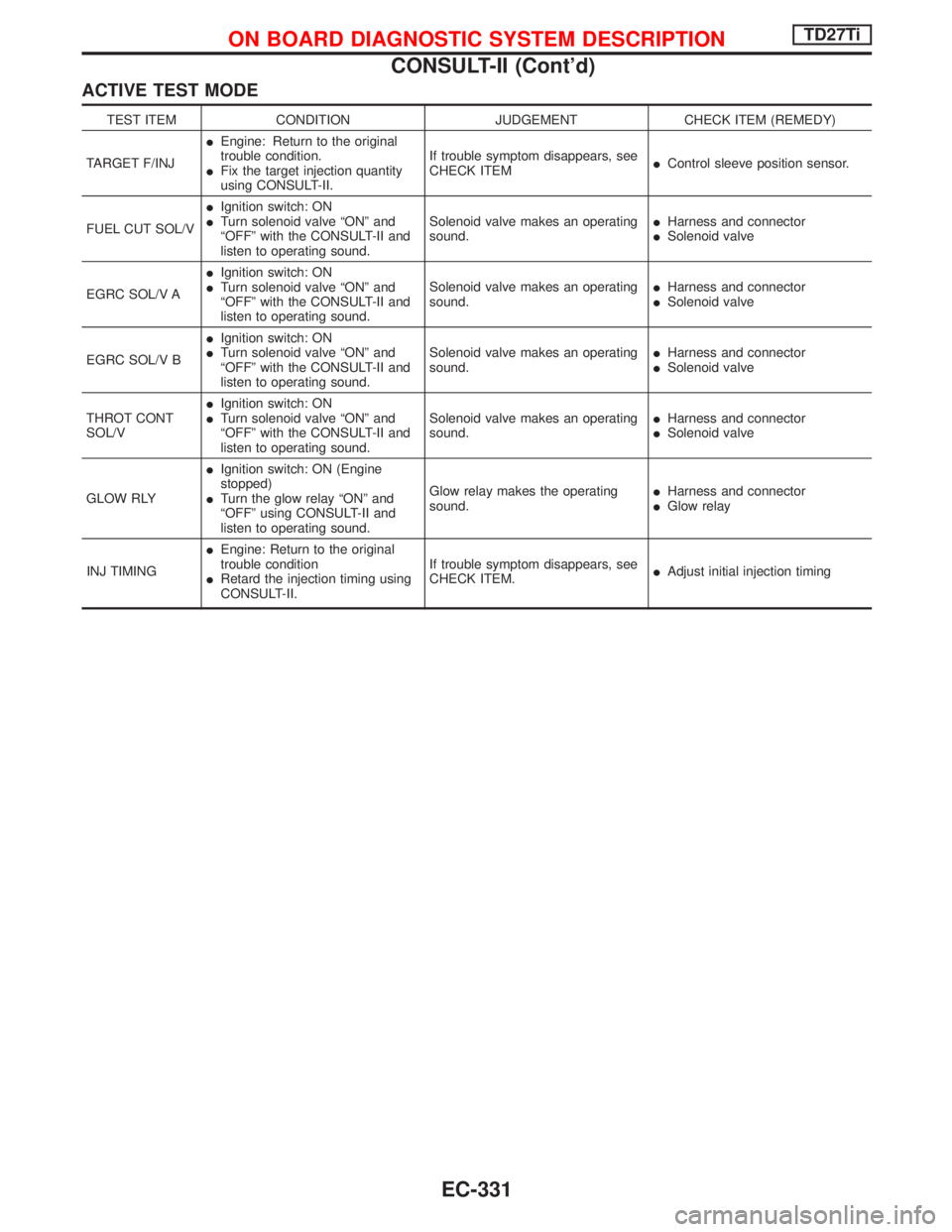
ACTIVE TEST MODE
TEST ITEM CONDITION JUDGEMENT CHECK ITEM (REMEDY)
TARGET F/INJIEngine: Return to the original
trouble condition.
IFix the target injection quantity
using CONSULT-II.If trouble symptom disappears, see
CHECK ITEMIControl sleeve position sensor.
FUEL CUT SOL/VIIgnition switch: ON
ITurn solenoid valve ªONº and
ªOFFº with the CONSULT-II and
listen to operating sound.Solenoid valve makes an operating
sound.IHarness and connector
ISolenoid valve
EGRC SOL/V AIIgnition switch: ON
ITurn solenoid valve ªONº and
ªOFFº with the CONSULT-II and
listen to operating sound.Solenoid valve makes an operating
sound.IHarness and connector
ISolenoid valve
EGRC SOL/V BIIgnition switch: ON
ITurn solenoid valve ªONº and
ªOFFº with the CONSULT-II and
listen to operating sound.Solenoid valve makes an operating
sound.IHarness and connector
ISolenoid valve
THROT CONT
SOL/VIIgnition switch: ON
ITurn solenoid valve ªONº and
ªOFFº with the CONSULT-II and
listen to operating sound.Solenoid valve makes an operating
sound.IHarness and connector
ISolenoid valve
GLOW RLYIIgnition switch: ON (Engine
stopped)
ITurn the glow relay ªONº and
ªOFFº using CONSULT-II and
listen to operating sound.Glow relay makes the operating
sound.IHarness and connector
IGlow relay
INJ TIMINGIEngine: Return to the original
trouble condition
IRetard the injection timing using
CONSULT-II.If trouble symptom disappears, see
CHECK ITEM.IAdjust initial injection timing
ON BOARD DIAGNOSTIC SYSTEM DESCRIPTIONTD27Ti
CONSULT-II (Cont'd)
EC-331
Page 696 of 1767
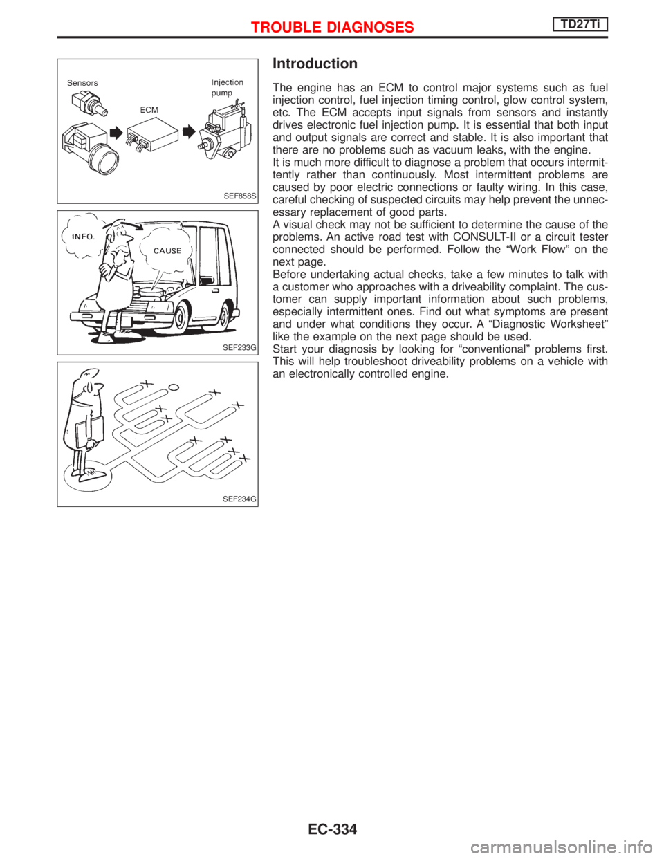
Introduction
The engine has an ECM to control major systems such as fuel
injection control, fuel injection timing control, glow control system,
etc. The ECM accepts input signals from sensors and instantly
drives electronic fuel injection pump. It is essential that both input
and output signals are correct and stable. It is also important that
there are no problems such as vacuum leaks, with the engine.
It is much more difficult to diagnose a problem that occurs intermit-
tently rather than continuously. Most intermittent problems are
caused by poor electric connections or faulty wiring. In this case,
careful checking of suspected circuits may help prevent the unnec-
essary replacement of good parts.
A visual check may not be sufficient to determine the cause of the
problems. An active road test with CONSULT-II or a circuit tester
connected should be performed. Follow the ªWork Flowº on the
next page.
Before undertaking actual checks, take a few minutes to talk with
a customer who approaches with a driveability complaint. The cus-
tomer can supply important information about such problems,
especially intermittent ones. Find out what symptoms are present
and under what conditions they occur. A ªDiagnostic Worksheetº
like the example on the next page should be used.
Start your diagnosis by looking for ªconventionalº problems first.
This will help troubleshoot driveability problems on a vehicle with
an electronically controlled engine.
SEF858S
SEF233G
SEF234G
TROUBLE DIAGNOSESTD27Ti
EC-334
Page 700 of 1767

Basic Inspection
Precaution:
Perform Basic Inspection without electrical or mechanical
loads applied;
IHeadlamp switch is OFF,
IAir conditioner switch is OFF,
IRear defogger switch is OFF,
ISteering wheel is in the straight-ahead position, etc.
BEFORE STARTING
1. Check service records for any recent
repairs that may indicate a related
problem, or the current need for
scheduled maintenance.
2. Open engine hood and check the fol-
lowing:
IHarness connectors for improper con-
nections
IVacuum hoses for splits, kinks, or
improper connections
IWiring for improper connections,
pinches, or cuts
3.Using priming pump, bleed air from fuel
system. Refer to ªFuel Filter Checkº in
MA section.
CONNECT CONSULT-II TO THE
VEHICLE.
Connect ªCONSULT-IIº to the data link
connector for CONSULT-II and select
ªENGINEº from the menu.
DOES ENGINE START?
Ye s
ENo
Turn ignition switch to
ªLOCKº position, wait 5
seconds and then start
engine. If engine fails to
start, check diagnostic
trouble code (DTC).
Run engine for 10 minutes.
CHECK IDLE SPEED.
Read engine idle speed in ªDATA
MONITORº mode with CONSULT-II.
725 rpm 50 (in N position)
------------------------------------------------------------------------------------------------------------------------------------OR------------------------------------------------------------------------------------------------------------------------------------
Check idle speed using tachometer
tester.
725 rpm 50 (in N position)
(Go toqAon next page.)
SEF142I
NEF463
YEC237A
NEF464
SEF817Y
H
H
H
H
H
TROUBLE DIAGNOSESTD27Ti
EC-338