2002 NISSAN TERRANO Fuel system
[x] Cancel search: Fuel systemPage 421 of 1767
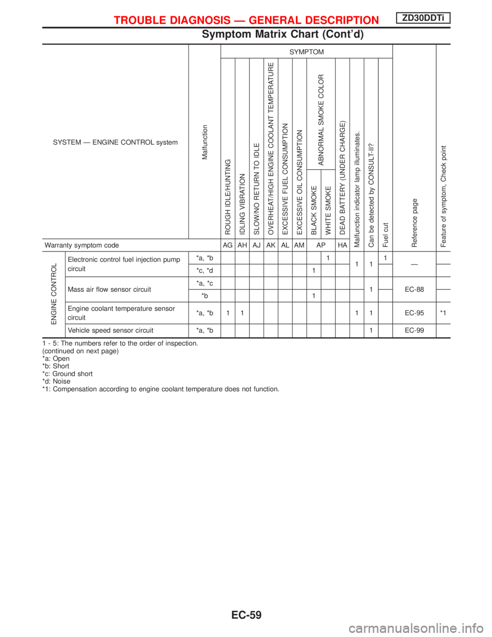
SYSTEM Ð ENGINE CONTROL system
Malfunction
SYMPTOM
Reference page
Feature of symptom, Check pointROUGH IDLE/HUNTING
IDLING VIBRATION
SLOW/NO RETURN TO IDLE
OVERHEAT/HIGH ENGINE COOLANT TEMPERATURE
EXCESSIVE FUEL CONSUMPTION
EXCESSIVE OIL CONSUMPTION
ABNORMAL SMOKE COLOR
DEAD BATTERY (UNDER CHARGE)
Malfunction indicator lamp illuminates.
Can be detected by CONSULT-II?
Fuel cutBLACK SMOKE
WHITE SMOKEWarranty symptom code AG AH AJ AK AL AM AP HA
ENGINE CONTROL
Electronic control fuel injection pump
circuit*a, *b 1
111
Ð
*c, *d 1
Mass air flow sensor circuit*a, *c
1 EC-88
*b 1
Engine coolant temperature sensor
circuit*a, *b 1 1 1 1 EC-95 *1
Vehicle speed sensor circuit *a, *b 1 EC-99
1 - 5: The numbers refer to the order of inspection.
(continued on next page)
*a: Open
*b: Short
*c: Ground short
*d: Noise
*1: Compensation according to engine coolant temperature does not function.
TROUBLE DIAGNOSIS Ð GENERAL DESCRIPTIONZD30DDTi
Symptom Matrix Chart (Cont'd)
EC-59
Page 422 of 1767
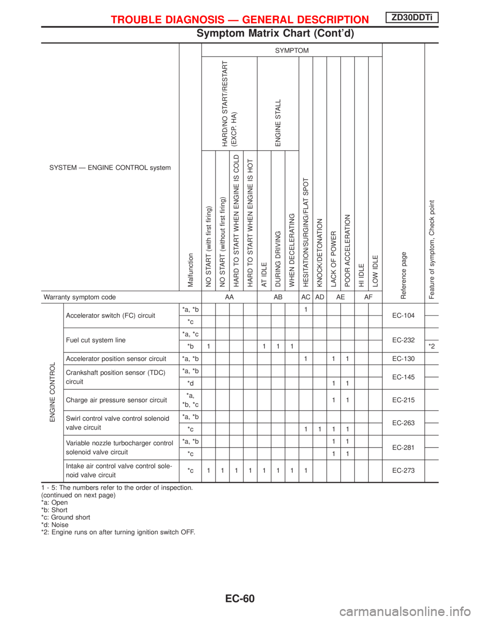
SYSTEM Ð ENGINE CONTROL system
Malfunction
SYMPTOM
Reference page
Feature of symptom, Check pointHARD/NO START/RESTART
(EXCP. HA)
ENGINE STALL
HESITATION/SURGING/FLAT SPOT
KNOCK/DETONATION
LACK OF POWER
POOR ACCELERATION
HI IDLE
LOW IDLE NO START (with first firing)
NO START (without first firing)
HARD TO START WHEN ENGINE IS COLD
HARD TO START WHEN ENGINE IS HOT
AT IDLE
DURING DRIVING
WHEN DECELERATINGWarranty symptom code AA AB AC AD AE AF
ENGINE CONTROL
Accelerator switch (FC) circuit*a, *b 1
EC-104
*c
Fuel cut system line*a, *c
EC-232
*b 1 1 1 1 *2
Accelerator position sensor circuit *a, *b 1 1 1 EC-130
Crankshaft position sensor (TDC)
circuit*a, *b
EC-145
*d 1 1
Charge air pressure sensor circuit*a,
*b, *c1 1 EC-215
Swirl control valve control solenoid
valve circuit*a, *b
EC-263
*c 1111
Variable nozzle turbocharger control
solenoid valve circuit*a, *b 1 1
EC-281
*c 1 1
Intake air control valve control sole-
noid valve circuit*c 11111111EC-273
1 - 5: The numbers refer to the order of inspection.
(continued on next page)
*a: Open
*b: Short
*c: Ground short
*d: Noise
*2: Engine runs on after turning ignition switch OFF.
TROUBLE DIAGNOSIS Ð GENERAL DESCRIPTIONZD30DDTi
Symptom Matrix Chart (Cont'd)
EC-60
Page 423 of 1767
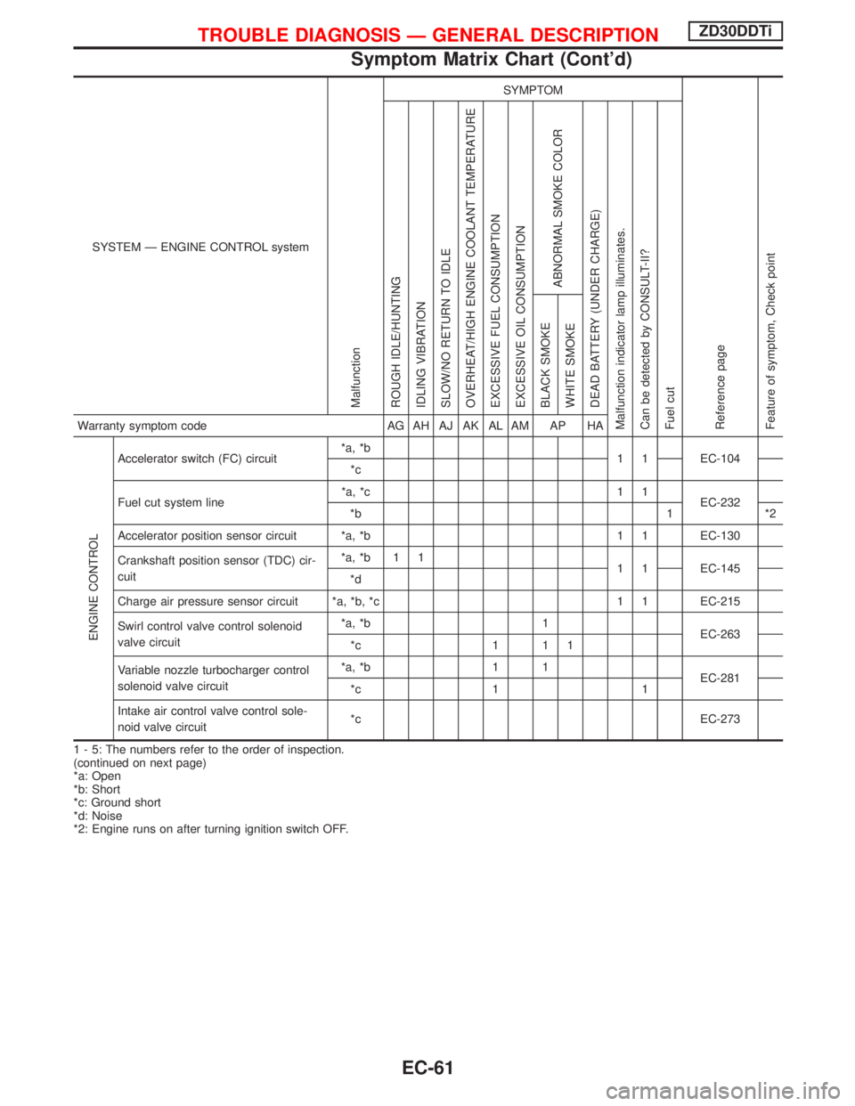
SYSTEM Ð ENGINE CONTROL system
Malfunction
SYMPTOM
Reference page
Feature of symptom, Check pointROUGH IDLE/HUNTING
IDLING VIBRATION
SLOW/NO RETURN TO IDLE
OVERHEAT/HIGH ENGINE COOLANT TEMPERATURE
EXCESSIVE FUEL CONSUMPTION
EXCESSIVE OIL CONSUMPTION
ABNORMAL SMOKE COLOR
DEAD BATTERY (UNDER CHARGE)
Malfunction indicator lamp illuminates.
Can be detected by CONSULT-II?
Fuel cutBLACK SMOKE
WHITE SMOKEWarranty symptom code AG AH AJ AK AL AM AP HA
ENGINE CONTROL
Accelerator switch (FC) circuit*a, *b
1 1 EC-104
*c
Fuel cut system line*a, *c 1 1
EC-232
*b 1 *2
Accelerator position sensor circuit *a, *b 1 1 EC-130
Crankshaft position sensor (TDC) cir-
cuit*a, *b 1 1
1 1 EC-145
*d
Charge air pressure sensor circuit *a, *b, *c 1 1 EC-215
Swirl control valve control solenoid
valve circuit*a, *b 1
EC-263
*c 1 1 1
Variable nozzle turbocharger control
solenoid valve circuit*a, *b 1 1
EC-281
*c 1 1
Intake air control valve control sole-
noid valve circuit*c EC-273
1 - 5: The numbers refer to the order of inspection.
(continued on next page)
*a: Open
*b: Short
*c: Ground short
*d: Noise
*2: Engine runs on after turning ignition switch OFF.
TROUBLE DIAGNOSIS Ð GENERAL DESCRIPTIONZD30DDTi
Symptom Matrix Chart (Cont'd)
EC-61
Page 425 of 1767
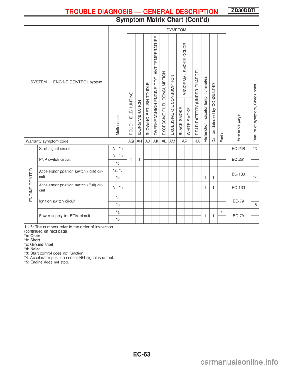
SYSTEM Ð ENGINE CONTROL system
Malfunction
SYMPTOM
Reference page
Feature of symptom, Check pointROUGH IDLE/HUNTING
IDLING VIBRATION
SLOW/NO RETURN TO IDLE
OVERHEAT/HIGH ENGINE COOLANT TEMPERATURE
EXCESSIVE FUEL CONSUMPTION
EXCESSIVE OIL CONSUMPTION
ABNORMAL SMOKE COLOR
DEAD BATTERY (UNDER CHARGE)
Malfunction indicator lamp illuminates.
Can be detected by CONSULT-II?
Fuel cutBLACK SMOKE
WHITE SMOKEWarranty symptom code AG AH AJ AK AL AM AP HA
ENGINE CONTROL
Start signal circuit *a, *b EC-248 *3
PNP switch circuit*a, *b
1 1 EC-251
*c
Accelerator position switch (Idle) cir-
cuit*a, *c
EC-130
*b 1 1 *4
Accelerator position switch (Full) cir-
cuit*a, *b 1 1 EC-130
Ignition switch circuit*a
EC-79
*b*5
Power supply for ECM circuit*a
111
EC-79
*b
1 - 5: The numbers refer to the order of inspection.
(continued on next page)
*a: Open
*b: Short
*c: Ground short
*d: Noise
*3: Start control does not function.
*4: Accelerator position sensor NG signal is output.
*5: Engine does not stop.
TROUBLE DIAGNOSIS Ð GENERAL DESCRIPTIONZD30DDTi
Symptom Matrix Chart (Cont'd)
EC-63
Page 427 of 1767
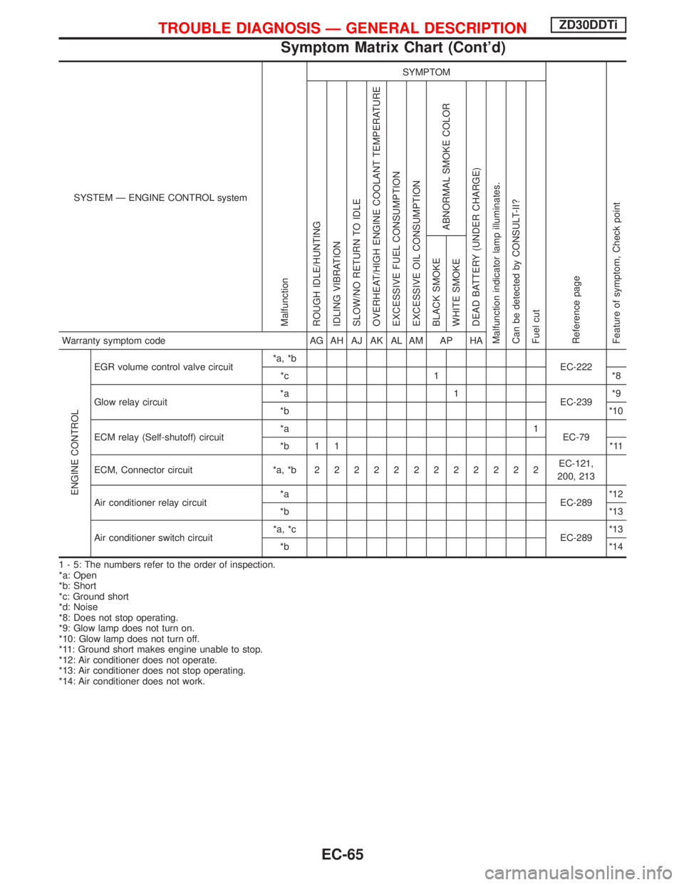
SYSTEM Ð ENGINE CONTROL system
Malfunction
SYMPTOM
Reference page
Feature of symptom, Check pointROUGH IDLE/HUNTING
IDLING VIBRATION
SLOW/NO RETURN TO IDLE
OVERHEAT/HIGH ENGINE COOLANT TEMPERATURE
EXCESSIVE FUEL CONSUMPTION
EXCESSIVE OIL CONSUMPTION
ABNORMAL SMOKE COLOR
DEAD BATTERY (UNDER CHARGE)
Malfunction indicator lamp illuminates.
Can be detected by CONSULT-II?
Fuel cutBLACK SMOKE
WHITE SMOKEWarranty symptom code AG AH AJ AK AL AM AP HA
ENGINE CONTROL
EGR volume control valve circuit*a, *b
EC-222
*c 1 *8
Glow relay circuit*a 1
EC-239*9
*b*10
ECM relay (Self-shutoff) circuit*a 1
EC-79
*b 1 1 *11
ECM, Connector circuit *a, *b222222222222EC-121,
200, 213
Air conditioner relay circuit*a
EC-289*12
*b*13
Air conditioner switch circuit*a, *c
EC-289*13
*b*14
1 - 5: The numbers refer to the order of inspection.
*a: Open
*b: Short
*c: Ground short
*d: Noise
*8: Does not stop operating.
*9: Glow lamp does not turn on.
*10: Glow lamp does not turn off.
*11: Ground short makes engine unable to stop.
*12: Air conditioner does not operate.
*13: Air conditioner does not stop operating.
*14: Air conditioner does not work.
TROUBLE DIAGNOSIS Ð GENERAL DESCRIPTIONZD30DDTi
Symptom Matrix Chart (Cont'd)
EC-65
Page 485 of 1767
Description
SYSTEM DESCRIPTION
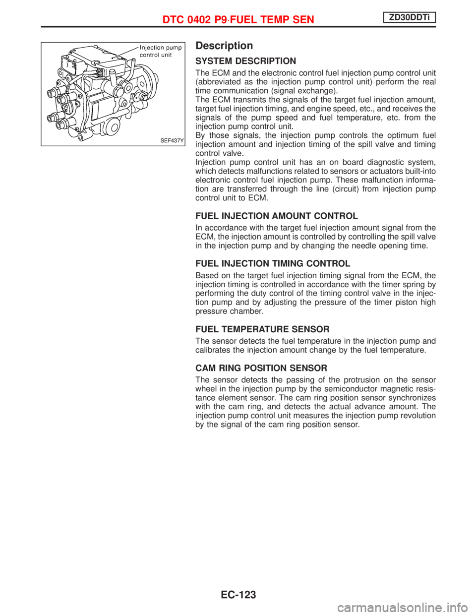
The ECM and the electronic control fuel injection pump control unit
(abbreviated as the injection pump control unit) perform the real
time communication (signal exchange).
The ECM transmits the signals of the target fuel injection amount,
target fuel injection timing, and engine speed, etc., and receives the
signals of the pump speed and fuel temperature, etc. from the
injection pump control unit.
By those signals, the injection pump controls the optimum fuel
injection amount and injection timing of the spill valve and timing
control valve.
Injection pump control unit has an on board diagnostic system,
which detects malfunctions related to sensors or actuators built-into
electronic control fuel injection pump. These malfunction informa-
tion are transferred through the line (circuit) from injection pump
control unit to ECM.
FUEL INJECTION AMOUNT CONTROL
In accordance with the target fuel injection amount signal from the
ECM, the injection amount is controlled by controlling the spill valve
in the injection pump and by changing the needle opening time.
FUEL INJECTION TIMING CONTROL
Based on the target fuel injection timing signal from the ECM, the
injection timing is controlled in accordance with the timer spring by
performing the duty control of the timing control valve in the injec-
tion pump and by adjusting the pressure of the timer piston high
pressure chamber.
FUEL TEMPERATURE SENSOR
The sensor detects the fuel temperature in the injection pump and
calibrates the injection amount change by the fuel temperature.
CAM RING POSITION SENSOR
The sensor detects the passing of the protrusion on the sensor
wheel in the injection pump by the semiconductor magnetic resis-
tance element sensor. The cam ring position sensor synchronizes
with the cam ring, and detects the actual advance amount. The
injection pump control unit measures the injection pump revolution
by the signal of the cam ring position sensor.
SEF437Y
DTC 0402 P9×FUEL TEMP SENZD30DDTi
EC-123
Page 523 of 1767
Description
SYSTEM DESCRIPTION
The ECM and the electronic control fuel injection pump control unit
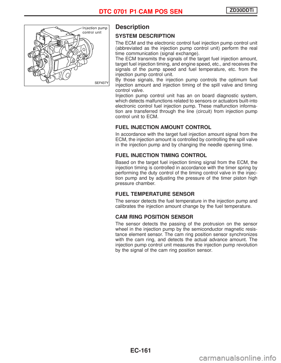
(abbreviated as the injection pump control unit) perform the real
time communication (signal exchange).
The ECM transmits the signals of the target fuel injection amount,
target fuel injection timing, and engine speed, etc., and receives the
signals of the pump speed and fuel temperature, etc. from the
injection pump control unit.
By those signals, the injection pump controls the optimum fuel
injection amount and injection timing of the spill valve and timing
control valve.
Injection pump control unit has an on board diagnostic system,
which detects malfunctions related to sensors or actuators built-into
electronic control fuel injection pump. These malfunction informa-
tion are transferred through the line (circuit) from injection pump
control unit to ECM.
FUEL INJECTION AMOUNT CONTROL
In accordance with the target fuel injection amount signal from the
ECM, the injection amount is controlled by controlling the spill valve
in the injection pump and by changing the needle opening time.
FUEL INJECTION TIMING CONTROL
Based on the target fuel injection timing signal from the ECM, the
injection timing is controlled in accordance with the timer spring by
performing the duty control of the timing control valve in the injec-
tion pump and by adjusting the pressure of the timer piston high
pressure chamber.
FUEL TEMPERATURE SENSOR
The sensor detects the fuel temperature in the injection pump and
calibrates the injection amount change by the fuel temperature.
CAM RING POSITION SENSOR
The sensor detects the passing of the protrusion on the sensor
wheel in the injection pump by the semiconductor magnetic resis-
tance element sensor. The cam ring position sensor synchronizes
with the cam ring, and detects the actual advance amount. The
injection pump control unit measures the injection pump revolution
by the signal of the cam ring position sensor.
SEF437Y
DTC 0701 P1×CAM POS SENZD30DDTi
EC-161
Page 530 of 1767
Description
SYSTEM DESCRIPTION
The ECM and the electronic control fuel injection pump control unit
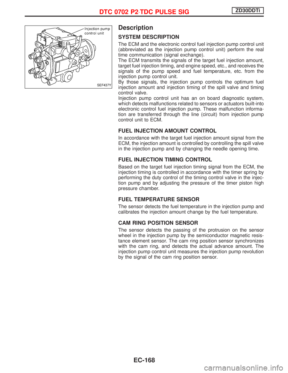
(abbreviated as the injection pump control unit) perform the real
time communication (signal exchange).
The ECM transmits the signals of the target fuel injection amount,
target fuel injection timing, and engine speed, etc., and receives the
signals of the pump speed and fuel temperature, etc. from the
injection pump control unit.
By those signals, the injection pump controls the optimum fuel
injection amount and injection timing of the spill valve and timing
control valve.
Injection pump control unit has an on board diagnostic system,
which detects malfunctions related to sensors or actuators built-into
electronic control fuel injection pump. These malfunction informa-
tion are transferred through the line (circuit) from injection pump
control unit to ECM.
FUEL INJECTION AMOUNT CONTROL
In accordance with the target fuel injection amount signal from the
ECM, the injection amount is controlled by controlling the spill valve
in the injection pump and by changing the needle opening time.
FUEL INJECTION TIMING CONTROL
Based on the target fuel injection timing signal from the ECM, the
injection timing is controlled in accordance with the timer spring by
performing the duty control of the timing control valve in the injec-
tion pump and by adjusting the pressure of the timer piston high
pressure chamber.
FUEL TEMPERATURE SENSOR
The sensor detects the fuel temperature in the injection pump and
calibrates the injection amount change by the fuel temperature.
CAM RING POSITION SENSOR
The sensor detects the passing of the protrusion on the sensor
wheel in the injection pump by the semiconductor magnetic resis-
tance element sensor. The cam ring position sensor synchronizes
with the cam ring, and detects the actual advance amount. The
injection pump control unit measures the injection pump revolution
by the signal of the cam ring position sensor.
SEF437Y
DTC 0702 P2×TDC PULSE SIGZD30DDTi
EC-168