2002 NISSAN TERRANO oil pressure
[x] Cancel search: oil pressurePage 1409 of 1767
qC
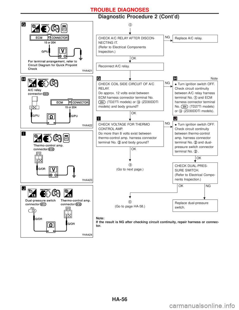
CHECK A/C RELAY AFTER DISCON-
NECTING IT.
(Refer to Electrical Components
Inspection.)
OK
ENG
Replace A/C relay.
Reconnect A/C relay.
Note
CHECK COIL SIDE CIRCUIT OF A/C
RELAY.
Do approx. 12 volts exist between
ECM harness connector terminal No.
204(TD27Ti models) orq15(ZD30DDTi
models) and body ground?
OK
ENG
ITurn ignition switch OFF.
Check circuit continuity
between A/C relay harness
terminal No.q
1and ECM
harness connector terminal
No.
204(TD27Ti models)
orq
15(ZD30DDTi models).
CHECK VOLTAGE FOR THERMO
CONTROL AMP.
Do more than 8 volts exist between
thermo-control amp. harness connector
terminal No.q
2and body ground?
OK
ENG
ITurn ignition switch OFF.
Check circuit continuity
between thermo-control
amp. harness connector
terminal No.q
2and dual-
pressure switch connector
terminal No.q
2.
OK
q
D
(Go to next page.)CHECK DUAL-PRES-
SURE SWITCH.
(Refer to Electrical Compo-
nents Inspection.)
NGOK
q
E
(Go to page HA-58.)Replace dual-pressure
switch.
Note:
If the result is NG after checking circuit continuity, repair harness or connec-
tor.
YHA421
YHA422
YHA423
YHA424
H
H
H
H
HH
HH
TROUBLE DIAGNOSES
Diagnostic Procedure 2 (Cont'd)
HA-56
Page 1414 of 1767
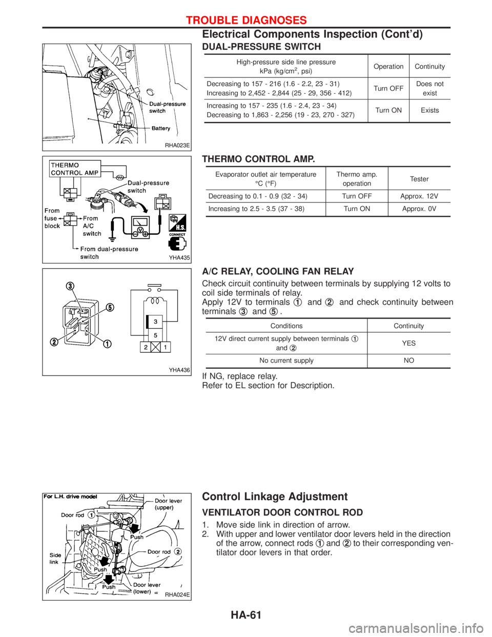
DUAL-PRESSURE SWITCH
High-pressure side line pressure
kPa (kg/cm2, psi)Operation Continuity
Decreasing to 157 - 216 (1.6 - 2.2, 23 - 31)
Increasing to 2,452 - 2,844 (25 - 29, 356 - 412)Turn OFFDoes not
exist
Increasing to 157 - 235 (1.6 - 2.4, 23 - 34)
Decreasing to 1,863 - 2,256 (19 - 23, 270 - 327)Turn ON Exists
THERMO CONTROL AMP.
Evaporator outlet air temperature
ÉC (ÉF)Thermo amp.
operationTester
Decreasing to 0.1 - 0.9 (32 - 34) Turn OFF Approx. 12V
Increasing to 2.5 - 3.5 (37 - 38) Turn ON Approx. 0V
A/C RELAY, COOLING FAN RELAY
Check circuit continuity between terminals by supplying 12 volts to
coil side terminals of relay.
Apply 12V to terminalsq
1andq2and check continuity between
terminalsq
3andq5.
Conditions Continuity
12V direct current supply between terminalsq
1
andq2YES
No current supply NO
If NG, replace relay.
Refer to EL section for Description.
Control Linkage Adjustment
VENTILATOR DOOR CONTROL ROD
1. Move side link in direction of arrow.
2. With upper and lower ventilator door levers held in the direction
of the arrow, connect rodsq
1andq2to their corresponding ven-
tilator door levers in that order.
RHA023E
YHA435
YHA436
RHA024E
TROUBLE DIAGNOSES
Electrical Components Inspection (Cont'd)
HA-61
Page 1420 of 1767
Clutch pedal .............................................CL-3, 4, 5
Clutch release mechanism ...............................CL-9
Coil spring (rear) ......................................RA-14, 16
Collision diagnosis..........................................RS-57
Combination lamp, front, removal and
installation .....................................................BT-6
Combination lamp, rear, removal and
installation .....................................................BT-8
Combination meter (needle type) ...................EL-70
Combination meter removal and instal-
lation - See Instrument panel......................BT-16
Combination switch...................................EL-23, 24
Component Location (manual A/C) ..................HA-7
Compression pressure ...................................EM-10
Compressor clutch removal and
installation ...................................................HA-24
Compressor mounting ....................................HA-21
Connecting rod...............................................EM-73
Connecting rod bearing clearance.................EM-77
Connecting rod bushing clearance ................EM-73
Console box - See Instrument panel ..............BT-16
CONSULT for ABS .........................................BR-58
CONSULT for engine .............................EC-39, 327
CONSULT-II general information.....................GI-26
Control lever (M/T) .........................................MT-13
Control lever (Transfer) .....................................TF-8
Control sleeve position sensor .....................EC-414
Control valve (A/T) ........................................AT-113
COOL/F - Wiring diagram ............................EC-112
Coolant mixture ratio ...................MA-17, 20, 22, 31
Coolant replacement ...............MA-5, 17, 20, 22, 31
Cooling circuit (engine)...............................LC-9, 27
Cooling fan ...............................................LC-15, 33
Cooling fan control .......................................EC-109
Cooling fan relay ..........................................EC-426
Corrosion protection..........................................BT-5
Counter gear (M/T) .........................................MT-11
Counter gear (Transfer) ............................TF-10, 20
Cowl top ..........................................................BT-21
Cowl top cover ................................................BT-21
Crankcase emission control system -
See positive crankcase ventilation .....EC-23, 312
Crankcase ventilation system - See
Positive crankcase ventilation ............EC-23, 312
Crankshaft ......................................................EM-76
Crankshaft position sensor (TDC) .......EC-145, 385
Cylinder block ................................................EM-66
Cylinder head .................................................EM-52
D
Data link connector ................................EC-39, 327
Daytime light system ..........................EL-29, 30, 31
DEF - Wiring diagram ...................................EL-107
Defroster door control rod adjustment ...........HA-62
Diagnosis sensor unit .....................................RS-11
Diagnostic trouble code (DTC) for OBD
system ................................................EC-33, 321
Differential carrier assembly ....................PD-29, 53Differential carrier disassembly..........PD-18, 38, 40
Differential gear oil replacement .......MA-36, 38, 39
Dimensions ......................................................GI-31
D/LOCK - Wiring diagram .............................EL-140
Door glass .......................................................BT-10
Door lock .........................................................BT-10
Door mirror ......................................................BT-48
Door trim .........................................................BT-19
Door, front .......................................................BT-10
Door, rear ........................................................BT-12
Drive belt inspection ................................MA-20, 28
Drive chain (Transfer) .....................................TF-10
Drive pinion diff. inspection ......................PD-20, 42
Drive pinion height ...................................PD-21, 49
Drive plate runout ..........................................EM-94
Drive shaft ........................................................MA-5
Drive shaft (front)..................................FA-4, 12, 22
Driver air bag..................................................RS-14
Dropping resistor (A/T)....................................AT-86
Dual pressure switch..................................HA-9, 61
E
ECM input/output signal .........................EC-69, 346
ECM relay ......................................EC-80, 209, 353
ECMRLY - Wiring diagram ...........................EC-210
ECTS - Wiring diagram ..................................EC-96
EGR control (EGRC) - solenoid valve .........EC-431
EGR control valve ........................................EC-439
EGR volume control valve ...........................EC-222
EGVC/V - Wiring diagram ............................EC-225
Electrical unit ................................................Foldout
Electronic fuel injection pump ......................EC-318
Engine compartment .......................................BT-50
Engine control circuit diagram ...............EC-16, 302
Engine control component parts
location ...............................................EC-12, 300
Engine control module (ECM) ......EC-69, 121, 200,
202, 213, 346,
407, 444
Engine control system diagram and
chart....................................................EC-17, 303
Engine coolant temperature sensor
(ECTS)................................................EC-95, 361
Engine oil filter replacement..........MA-5, 20, 21, 30
Engine oil precautions .......................................GI-6
Engine oil replacement ......................MA-20, 21, 29
Engine removal ..............................................EM-63
Engine room - See Engine
compartment ...............................................BT-50
Engine serial number ......................................GI-30
Exhaust manifold ...........................................EM-18
Exhaust system ..........................................FE-4, 10
Exhaust system inspection ............................MA-36
Extension tube diff. ..................................PD-19, 28
Exterior ............................................................BT-21
Exterior lamp.............................................EL-45, 60
ALPHABETICAL INDEX
IDX-3
Page 1422 of 1767
INT/V - Wiring diagram ................................EC-274
Intake air control valve control solenoid
valve .........................................................EC-273
Intake Air Volume .........................................EC-143
Intake door control linkage adjustment ..........HA-63
Intake manifold...............................................EM-12
Interior .............................................................BT-18
Interior lamp ..............................................EL-61, 66
ISO 15031-2 Terminology................................GI-35
K
Knuckle spindle ...............................................FA-20
L
License lamp ...................................................EL-45
Limited slip diff. adjustment............................PD-45
Limited slip diff. assembly ..............................PD-47
Limited slip diff. disassembly ...................PD-43, 44
Limited slip diff. inspection .............................PD-44
Line pressure solenoid valve ..........................AT-84
Line pressure test (A/T) ..........................AT-30, 196
Liquid gasket application .................................EM-3
Location of electrical units ............EL-241, 242, 244
Lock, door ...........................................BT-10, 12, 14
Low and reverse brake .................................AT-161
LSV (Load sensing valve) ..............................BR-10
Lubricants.......................................................MA-17
Lubrication circuit (engine) .........................LC-3, 20
Lubrication oil A/C ....................................HA-22, 64
Lubrication-locks, hinges and hood
latches ..................................................MA-36, 45
Luggage compartment trim .............................BT-18
M
MAFS - Wiring diagram..................................EC-90
MAIN - Wiring diagram...................................EC-80
Main drive gear (M/T) .....................................MT-11
Main gear (Transfer) .................................TF-10, 21
Mainshaft (M/T) ..............................................MT-11
Mainshaft (Transfer)..................................TF-10, 17
Maintenance ...........MA-5, 8, 11, 14, 20, 36, 48, 49
MAJOR OVERHALL ......................................AT-119
Major overhaul (Transfer) .................................TF-9
Malfunction indicator (MI).......................EC-34, 322
Manifold tightening torque (intake &
exhaust) ...............................................MA-20, 28
Manual transmission number ..........................GI-30
Manual transmission oil replacement ......MA-36, 37
Map lamp ........................................................EL-66
Mass air flow sensor (MAFS) ................EC-88, 356
Master cylinder (brake) ..................................BR-16
Meter .........................................................EL-70, 71
METER - Wiring diagram................................EL-72
MIL/DL - Wiring diagram ..............................EC-291MIRROR - Wiring diagram............................EL-131
Mirror, door......................................................BT-48
Model variation ................................................GI-28
Molding - See Exterior ....................................BT-21
M/T major overhaul ........................................MT-10
M/T removal and installation ........................MT-7, 8
Mud guard - See Exterior ...............................BT-21
MULTI - Wiring diagram................................EL-169
Multi-remote control system .........EL-168, 177, 179
Multiport fuel injection precautions ....................GI-5
N
NATS (Nissan anti-theft
system) .....................EL-186, 187, 188, 195, 208
NATS - Wiring diagram .................................EL-189
NATS V2.0 precautions (For Europe) ...............GI-4
Needle lift sensor .........................................EC-427
NVH troubleshooting (EM) ...............................EM-8
O
Oil change (capacity) ............MA-21, 29, 37, 38, 39
Oil change (interval) ..................................MA-5, 35
Oil cooler (engine) ............................................LC-8
Oil pan (engine) .............................................EM-22
Oil pump (A/T)...............................................AT-134
Oil seal replacement (engine)........................EM-50
Oil seal replacement (front final drive
4WD)...........................................................PD-10
OILPSW - Wiring diagram............................EC-451
On board diagnostic system ..................EC-33, 321
Overdrive control switch..................................AT-95
Overheat .......................................................EC-109
Overrun clutch solenoid valve ..................AT-69, 70
Oversize piston ..............................................EM-74
P
Park/Neutral position switch .........................EC-251
Park/neutral position switch (A/T) ...........AT-88, 114
Parking drum brake ........................................BR-35
Parking lamp ...................................................EL-45
PCV (positive crankcase ventilation) .....EC-23, 312
Periodic maintenance ......................................MA-5
Piston pin inspection ......................................EM-71
Piston ring inspection.....................................EM-72
PNP/SW - Wiring diagram ...........................EC-252
POWER - Wiring diagram.................................EL-8
Power door lock ...EL-137, 138, 145, 146, 148, 158
Power steering fluid level...............MA-36, 44, ST-4
Power steering gear .................................ST-12, 22
Power steering hydraulic pressure ...................ST-7
Power steering oil pump ...........................ST-16, 22
Power steering system bleeding.......................ST-5
Power supply routing ....................................EL-6, 8
Power window ...............................................EL-133
ALPHABETICAL INDEX
IDX-5
Page 1426 of 1767
ENGINE LUBRICATION &
COOLING SYSTEMS
SECTION
LC
CONTENTS
ZD
PRECAUTIONS AND PREPARATION............................2
Liquid Gasket Application Procedure ..........................2
Special Service Tools ..................................................2
ENGINE LUBRICATION SYSTEM..................................3
Lubricating Circuit ........................................................3
Oil Pressure Check......................................................4
Oil Pump ......................................................................5
Oil Jet...........................................................................7
Oil Cooler .....................................................................8
ENGINE COOLING SYSTEM..........................................9
Cooling Circuit .............................................................9
System Check............................................................10
Water Pump ............................................................... 11
Thermostat .................................................................12
Water Outlet ...............................................................13
Radiator .....................................................................14
Cooling Fan (Crankshaft driven) ...............................15
EGR Cooler ...............................................................16
SERVICE DATA AND SPECIFICATIONS (SDS)..........17
Engine Lubrication System ........................................17
Engine Cooling System .............................................17TD27TiPREPARATION..............................................................18
PRECAUTION................................................................19
ENGINE LUBRICATION SYSTEM................................20
Lubrication Circuit ......................................................20
Oil Pressure Check....................................................21
Oil Pump ....................................................................22
Oil Filter Bracket ........................................................24
Oil Cooler ...................................................................25
Oil Jet.........................................................................26
ENGINE COOLING SYSTEM........................................27
Cooling Circuit ...........................................................27
System Inspection .....................................................28
Water Pump ...............................................................29
Thermostat .................................................................31
Radiator .....................................................................32
Cooling Fan ...............................................................33
SERVICE DATA AND SPECIFICATIONS (SDS)..........34
Engine Lubrication System ........................................34
Engine Cooling System .............................................34
Page 1427 of 1767
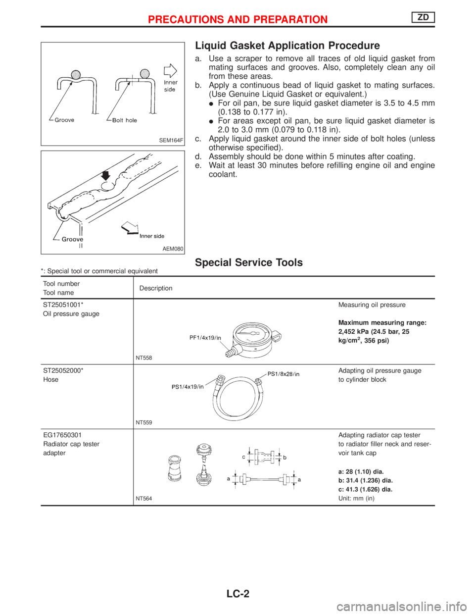
Liquid Gasket Application Procedure
a. Use a scraper to remove all traces of old liquid gasket from
mating surfaces and grooves. Also, completely clean any oil
from these areas.
b. Apply a continuous bead of liquid gasket to mating surfaces.
(Use Genuine Liquid Gasket or equivalent.)
IFor oil pan, be sure liquid gasket diameter is 3.5 to 4.5 mm
(0.138 to 0.177 in).
IFor areas except oil pan, be sure liquid gasket diameter is
2.0 to 3.0 mm (0.079 to 0.118 in).
c. Apply liquid gasket around the inner side of bolt holes (unless
otherwise specified).
d. Assembly should be done within 5 minutes after coating.
e. Wait at least 30 minutes before refilling engine oil and engine
coolant.
Special Service Tools*: Special tool or commercial equivalent
Tool number
Tool nameDescription
ST25051001*
Oil pressure gauge
NT558
Measuring oil pressure
Maximum measuring range:
2,452 kPa (24.5 bar, 25
kg/cm
2, 356 psi)
ST25052000*
Hose
NT559
Adapting oil pressure gauge
to cylinder block
EG17650301
Radiator cap tester
adapter
NT564
Adapting radiator cap tester
to radiator filler neck and reser-
voir tank cap
a: 28 (1.10) dia.
b: 31.4 (1.236) dia.
c: 41.3 (1.626) dia.
Unit: mm (in)
SEM164F
AEM080
PRECAUTIONS AND PREPARATIONZD
LC-2
Page 1429 of 1767
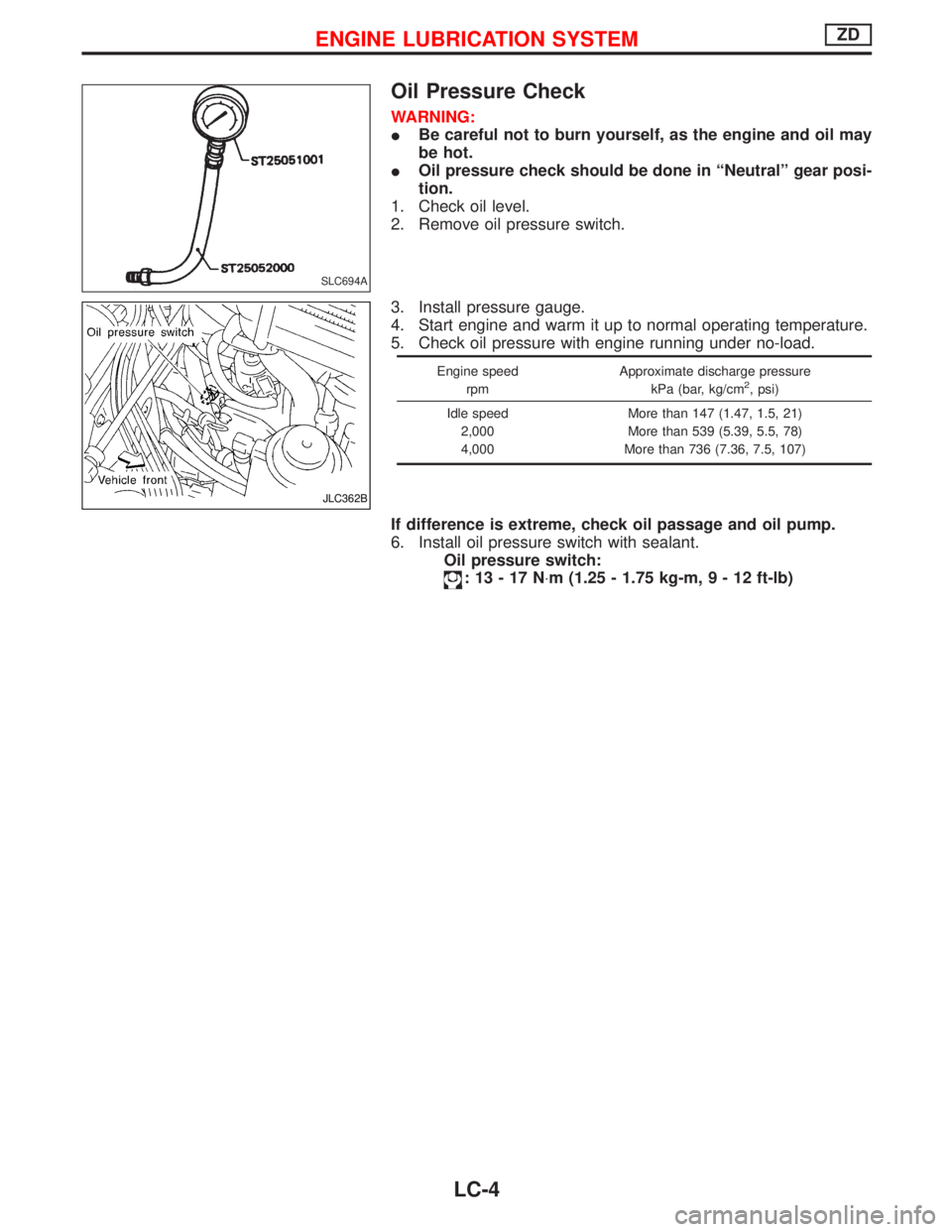
Oil Pressure Check
WARNING:
IBe careful not to burn yourself, as the engine and oil may
be hot.
IOil pressure check should be done in ªNeutralº gear posi-
tion.
1. Check oil level.
2. Remove oil pressure switch.
3. Install pressure gauge.
4. Start engine and warm it up to normal operating temperature.
5. Check oil pressure with engine running under no-load.
Engine speed
rpmApproximate discharge pressure
kPa (bar, kg/cm2, psi)
Idle speed
2,000
4,000More than 147 (1.47, 1.5, 21)
More than 539 (5.39, 5.5, 78)
More than 736 (7.36, 7.5, 107)
If difference is extreme, check oil passage and oil pump.
6. Install oil pressure switch with sealant.
Oil pressure switch:
:13-17N×m (1.25 - 1.75 kg-m,9-12ft-lb)
SLC694A
JLC362B
ENGINE LUBRICATION SYSTEMZD
LC-4
Page 1431 of 1767
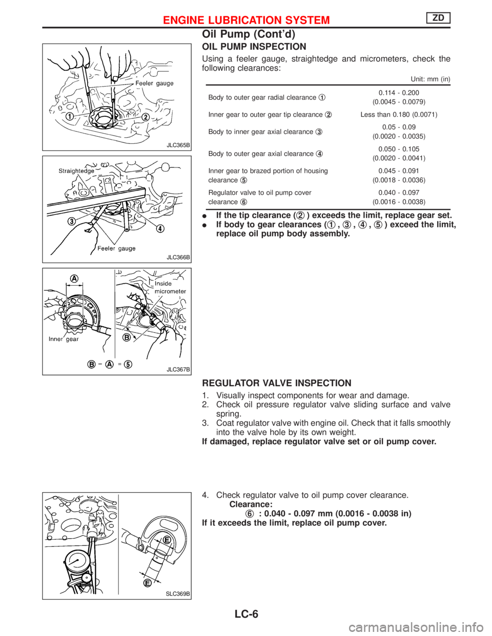
OIL PUMP INSPECTION
Using a feeler gauge, straightedge and micrometers, check the
following clearances:
Unit: mm (in)
Body to outer gear radial clearanceq10.114 - 0.200
(0.0045 - 0.0079)
Inner gear to outer gear tip clearanceq
2Less than 0.180 (0.0071)
Body to inner gear axial clearanceq
30.05 - 0.09
(0.0020 - 0.0035)
Body to outer gear axial clearanceq
40.050 - 0.105
(0.0020 - 0.0041)
Inner gear to brazed portion of housing
clearanceq
5
0.045 - 0.091
(0.0018 - 0.0036)
Regulator valve to oil pump cover
clearanceq
6
0.040 - 0.097
(0.0016 - 0.0038)
IIf the tip clearance (q2) exceeds the limit, replace gear set.
IIf body to gear clearances (q
1,q3,q4,q5) exceed the limit,
replace oil pump body assembly.
REGULATOR VALVE INSPECTION
1. Visually inspect components for wear and damage.
2. Check oil pressure regulator valve sliding surface and valve
spring.
3. Coat regulator valve with engine oil. Check that it falls smoothly
into the valve hole by its own weight.
If damaged, replace regulator valve set or oil pump cover.
4. Check regulator valve to oil pump cover clearance.
Clearance:
q
6: 0.040 - 0.097 mm (0.0016 - 0.0038 in)
If it exceeds the limit, replace oil pump cover.
JLC365B
JLC366B
JLC367B
SLC369B
ENGINE LUBRICATION SYSTEMZD
Oil Pump (Cont'd)
LC-6