Page 1602 of 1767
Propeller Shaft
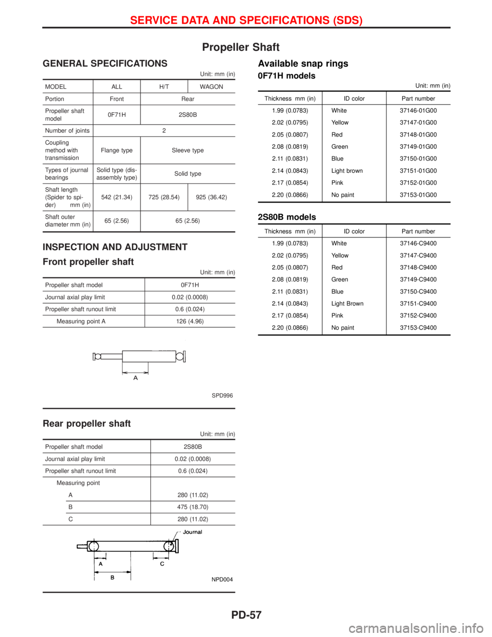
GENERAL SPECIFICATIONS
Unit: mm (in)
MODEL ALL H/T WAGON
Portion Front Rear
Propeller shaft
model0F71H 2S80B
Number of joints 2
Coupling
method with
transmissionFlange type Sleeve type
Types of journal
bearingsSolid type (dis-
assembly type)Solid type
Shaft length
(Spider to spi-
der) mm (in)542 (21.34) 725 (28.54) 925 (36.42)
Shaft outer
diameter mm (in)65 (2.56) 65 (2.56)
INSPECTION AND ADJUSTMENT
Front propeller shaft
Unit: mm (in)
Propeller shaft model 0F71H
Journal axial play limit 0.02 (0.0008)
Propeller shaft runout limit 0.6 (0.024)
Measuring point A 126 (4.96)
SPD996
Rear propeller shaft
Unit: mm (in)
Propeller shaft model 2S80B
Journal axial play limit 0.02 (0.0008)
Propeller shaft runout limit 0.6 (0.024)
Measuring point
A 280 (11.02)
B 475 (18.70)
C 280 (11.02)
NPD004
Available snap rings
0F71H models
Unit: mm (in)
Thickness mm (in) ID color Part number
1.99 (0.0783) White 37146-01G00
2.02 (0.0795) Yellow 37147-01G00
2.05 (0.0807) Red 37148-01G00
2.08 (0.0819) Green 37149-01G00
2.11 (0.0831) Blue 37150-01G00
2.14 (0.0843) Light brown 37151-01G00
2.17 (0.0854) Pink 37152-01G00
2.20 (0.0866) No paint 37153-01G00
2S80B models
Thickness mm (in) ID color Part number
1.99 (0.0783) White 37146-C9400
2.02 (0.0795) Yellow 37147-C9400
2.05 (0.0807) Red 37148-C9400
2.08 (0.0819) Green 37149-C9400
2.11 (0.0831) Blue 37150-C9400
2.14 (0.0843) Light Brown 37151-C9400
2.17 (0.0854) Pink 37152-C9400
2.20 (0.0866) No paint 37153-C9400
SERVICE DATA AND SPECIFICATIONS (SDS)
PD-57
Page 1603 of 1767
Final Drive
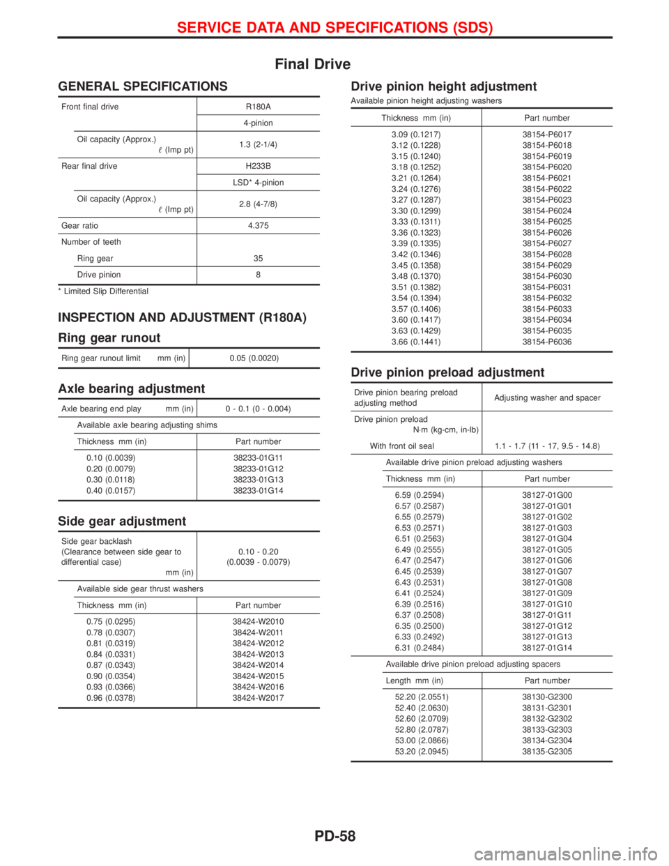
GENERAL SPECIFICATIONS
Front final drive R180A
4-pinion
Oil capacity (Approx.)
(Imp pt)1.3 (2-1/4)
Rear final drive H233B
LSD* 4-pinion
Oil capacity (Approx.)
(Imp pt)2.8 (4-7/8)
Gear ratio 4.375
Number of teeth
Ring gear 35
Drive pinion 8
* Limited Slip Differential
INSPECTION AND ADJUSTMENT (R180A)
Ring gear runout
Ring gear runout limit mm (in) 0.05 (0.0020)
Axle bearing adjustment
Axle bearing end play mm (in) 0 - 0.1 (0 - 0.004)
Available axle bearing adjusting shims
Thickness mm (in) Part number
0.10 (0.0039) 38233-01G11
0.20 (0.0079) 38233-01G12
0.30 (0.0118) 38233-01G13
0.40 (0.0157) 38233-01G14
Side gear adjustment
Side gear backlash
(Clearance between side gear to
differential case)
mm (in)0.10 - 0.20
(0.0039 - 0.0079)
Available side gear thrust washers
Thickness mm (in) Part number
0.75 (0.0295) 38424-W2010
0.78 (0.0307) 38424-W2011
0.81 (0.0319) 38424-W2012
0.84 (0.0331) 38424-W2013
0.87 (0.0343) 38424-W2014
0.90 (0.0354) 38424-W2015
0.93 (0.0366) 38424-W2016
0.96 (0.0378) 38424-W2017
Drive pinion height adjustment
Available pinion height adjusting washers
Thickness mm (in) Part number
3.09 (0.1217) 38154-P6017
3.12 (0.1228) 38154-P6018
3.15 (0.1240) 38154-P6019
3.18 (0.1252) 38154-P6020
3.21 (0.1264) 38154-P6021
3.24 (0.1276) 38154-P6022
3.27 (0.1287) 38154-P6023
3.30 (0.1299) 38154-P6024
3.33 (0.1311) 38154-P6025
3.36 (0.1323) 38154-P6026
3.39 (0.1335) 38154-P6027
3.42 (0.1346) 38154-P6028
3.45 (0.1358) 38154-P6029
3.48 (0.1370) 38154-P6030
3.51 (0.1382) 38154-P6031
3.54 (0.1394) 38154-P6032
3.57 (0.1406) 38154-P6033
3.60 (0.1417) 38154-P6034
3.63 (0.1429) 38154-P6035
3.66 (0.1441) 38154-P6036
Drive pinion preload adjustment
Drive pinion bearing preload
adjusting methodAdjusting washer and spacer
Drive pinion preload
N×m (kg-cm, in-lb)
With front oil seal 1.1 - 1.7 (11 - 17, 9.5 - 14.8)
Available drive pinion preload adjusting washers
Thickness mm (in) Part number
6.59 (0.2594) 38127-01G00
6.57 (0.2587) 38127-01G01
6.55 (0.2579) 38127-01G02
6.53 (0.2571) 38127-01G03
6.51 (0.2563) 38127-01G04
6.49 (0.2555) 38127-01G05
6.47 (0.2547) 38127-01G06
6.45 (0.2539) 38127-01G07
6.43 (0.2531) 38127-01G08
6.41 (0.2524) 38127-01G09
6.39 (0.2516) 38127-01G10
6.37 (0.2508) 38127-01G11
6.35 (0.2500) 38127-01G12
6.33 (0.2492) 38127-01G13
6.31 (0.2484) 38127-01G14
Available drive pinion preload adjusting spacers
Length mm (in) Part number
52.20 (2.0551) 38130-G2300
52.40 (2.0630) 38131-G2301
52.60 (2.0709) 38132-G2302
52.80 (2.0787) 38133-G2303
53.00 (2.0866) 38134-G2304
53.20 (2.0945) 38135-G2305
SERVICE DATA AND SPECIFICATIONS (SDS)
PD-58
Page 1605 of 1767
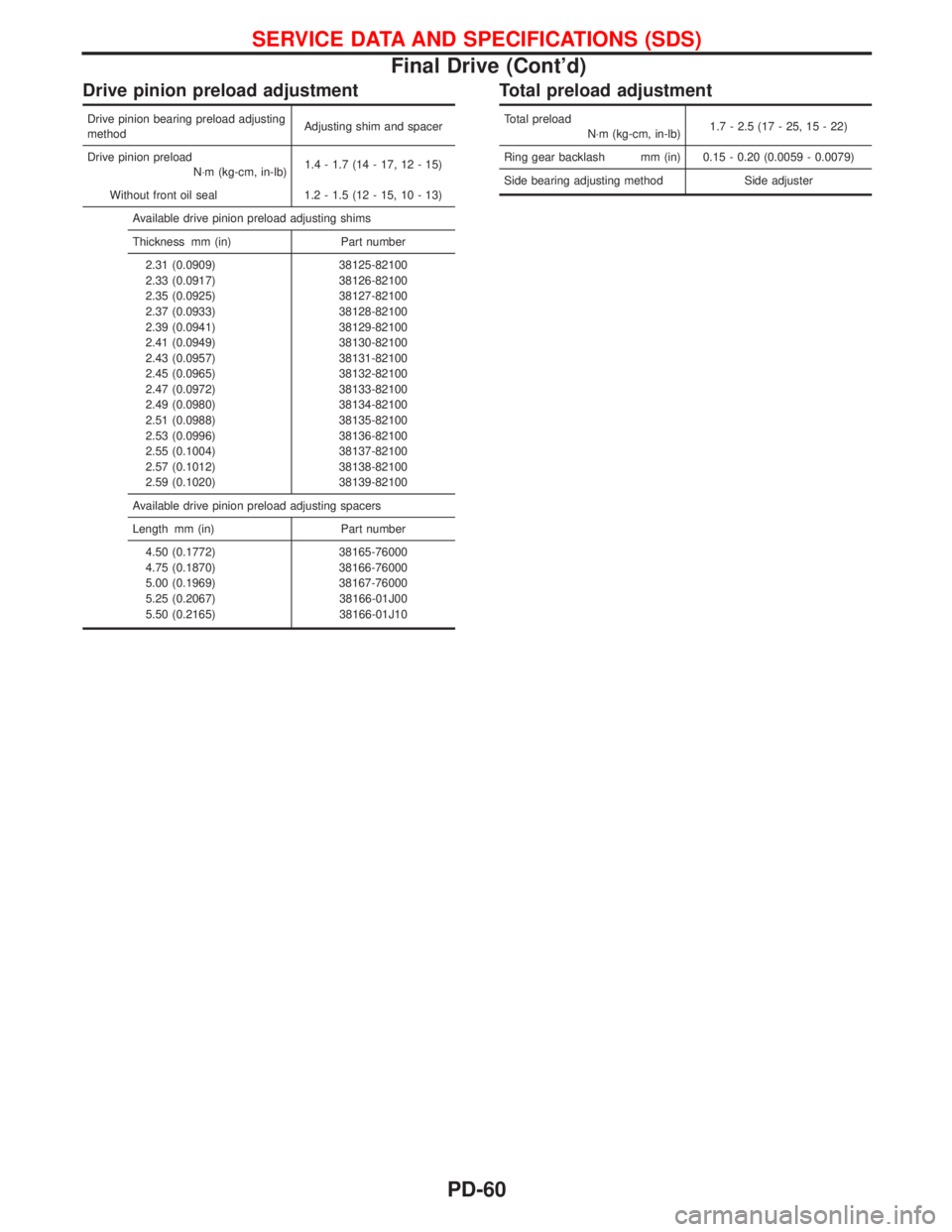
Drive pinion preload adjustment
Drive pinion bearing preload adjusting
methodAdjusting shim and spacer
Drive pinion preload
N×m (kg-cm, in-lb)1.4 - 1.7 (14 - 17, 12 - 15)
Without front oil seal 1.2 - 1.5 (12 - 15, 10 - 13)
Available drive pinion preload adjusting shims
Thickness mm (in) Part number
2.31 (0.0909) 38125-82100
2.33 (0.0917) 38126-82100
2.35 (0.0925) 38127-82100
2.37 (0.0933) 38128-82100
2.39 (0.0941) 38129-82100
2.41 (0.0949) 38130-82100
2.43 (0.0957) 38131-82100
2.45 (0.0965) 38132-82100
2.47 (0.0972) 38133-82100
2.49 (0.0980) 38134-82100
2.51 (0.0988) 38135-82100
2.53 (0.0996) 38136-82100
2.55 (0.1004) 38137-82100
2.57 (0.1012) 38138-82100
2.59 (0.1020) 38139-82100
Available drive pinion preload adjusting spacers
Length mm (in) Part number
4.50 (0.1772) 38165-76000
4.75 (0.1870) 38166-76000
5.00 (0.1969) 38167-76000
5.25 (0.2067) 38166-01J00
5.50 (0.2165) 38166-01J10
Total preload adjustment
Total preload
N×m (kg-cm, in-lb)1.7 - 2.5 (17 - 25, 15 - 22)
Ring gear backlash mm (in) 0.15 - 0.20 (0.0059 - 0.0079)
Side bearing adjusting method Side adjuster
SERVICE DATA AND SPECIFICATIONS (SDS)
Final Drive (Cont'd)
PD-60
Page 1621 of 1767
General Specifications
COIL SPRING AND SHOCK ABSORBER
Model Hardtop Wagon
Coil spring
Wire diameter mm (in) 13.0 (0.512) 13.5 (0.531)
Free length mm (in) 400 (15.75) 417 (16.42)
Spring constant
N/mm (kg/mm, lb/in)25.5 (2.6, 146) 29 (3.0, 168)
Shock absorber
Shock absorber type Non-adjustable (hydraulic)
Maximum length mm (in) 586 (23.07) 596 (23.46)
Minimum length mm (in) 350 (13.78) 356 (14.02)
Damping force
[at 0.3 m (1.0 ft)/sec.]
N (kg, lb)
Expansion990 - 1,330
(101 - 136,
223 - 229)1,169 - 1,563
(119 - 159,
223 - 351)
Compression346 - 524
(35.3 - 53.4,
77.8 - 117.8)301 - 461
(30.7 - 47.0,
67.7 - 103.6)
RA260
STABILIZER BAR
Model Hardtop Wagon
Diameter mm (in) 23 (0.91) 24 (0.94)
Spring constant
N/mm (kg/mm, lb/in)24.5 (2.5, 140) 29.0 (3.0, 166)
Inspection and Adjustment
WHEEL BEARING
Total end play mm (in) 0 (0)
SERVICE DATA AND SPECIFICATIONS (SDS)
RA-16
Page 1701 of 1767
4. Inspect pinion teeth.
IReplace pinion if teeth are worn or damaged. (Also check
condition of ring gear teeth.)
5. Inspect reduction gear teeth.
IReplace reduction gear if teeth are worn of damaged.
(Also check condition of armature shaft gear teeth.)
Brush Check
BRUSH
Check wear of brush.
Wear limit length:
Refer to SDS (SC-30).
IExcessive wear ... Replace.
BRUSH HOLDER
1. Perform insulation test between brush holder (positive side)
and its base (negative side).
IContinuity exists ... Replace.
2. Check brush to see if it moves smoothly.
IIf brush holder is bent, replace it; if sliding surface is dirty,
clean.
Field Coil Check
1. Continuity test (between field coil positive terminal and positive
brushes).
INo continuity ... Replace field coil.
2. Insulation test (between field coil positive terminal and yoke).
IContinuity exists ... Replace field coil.
SEL014Z
YEL549D
YEL550D
SEL103E
STARTING SYSTEM
Pinion/Clutch Check (Cont'd)
SC-20
Page 1703 of 1767
5. Check depth of insulating mold from commutator surface.
ILess than 0.2 mm (0.008 in) ... Undercut to 0.5 - 0.8 mm
(0.020 - 0.031 in)
Assembly
Carefully observe the following instructions.
GREASE POINT
IRear cover metal
IGear case metal
ICenter bracket metal
IFrictional surface of pinion
IMoving portion of shift lever
IPlunger of magnetic switch
IReduction gear
PINION PROTRUSION LENGTH ADJUSTMENT
Reduction gear type
Compare movement ªº in height of pinion when it is pushed out
with magnetic switch energized and when it is pulled out by hand
until it touches stopper.
Movement ªº:
Refer to SDS (SC-30).
INot in the specified value ... Adjust by adjusting plate.
SEL022Z
SEL497D
SEL573B
STARTING SYSTEM
Armature Check (Cont'd)
SC-22
Page 1711 of 1767
Battery
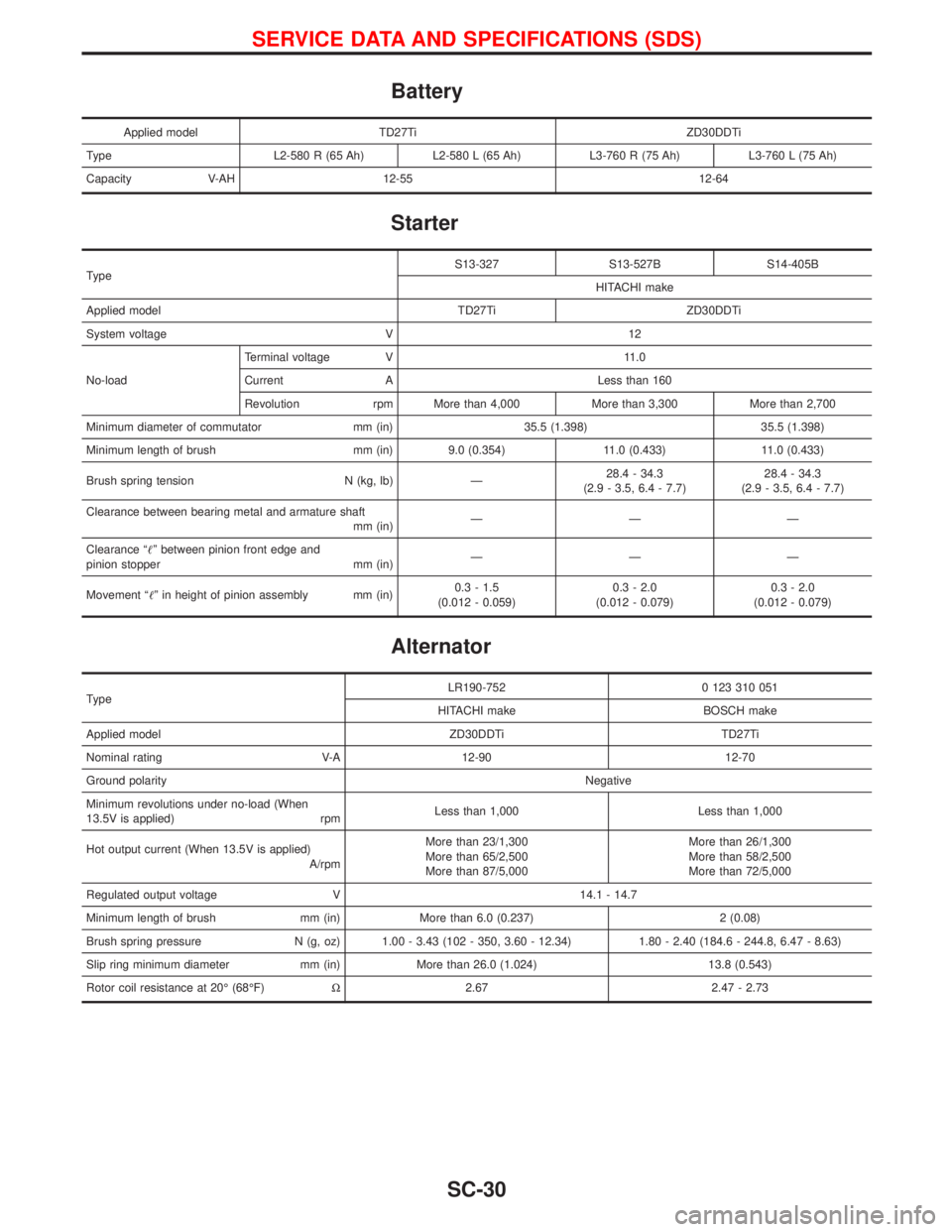
Applied model TD27Ti ZD30DDTi
Type L2-580 R (65 Ah) L2-580 L (65 Ah) L3-760 R (75 Ah) L3-760 L (75 Ah)
Capacity V-AH 12-55 12-64
Starter
TypeS13-327 S13-527B S14-405B
HITACHI make
Applied model TD27Ti ZD30DDTi
System voltage V 12
No-loadTerminal voltage V 11.0
Current A Less than 160
Revolution rpm More than 4,000 More than 3,300 More than 2,700
Minimum diameter of commutator mm (in) 35.5 (1.398) 35.5 (1.398)
Minimum length of brush mm (in) 9.0 (0.354) 11.0 (0.433) 11.0 (0.433)
Brush spring tension N (kg, lb) Ð28.4 - 34.3
(2.9 - 3.5, 6.4 - 7.7)28.4 - 34.3
(2.9 - 3.5, 6.4 - 7.7)
Clearance between bearing metal and armature shaft
mm (in)ÐÐÐ
Clearance ªº between pinion front edge and
pinion stopper mm (in)ÐÐÐ
Movement ªº in height of pinion assembly mm (in)0.3 - 1.5
(0.012 - 0.059)0.3 - 2.0
(0.012 - 0.079)0.3 - 2.0
(0.012 - 0.079)
Alternator
TypeLR190-752 0 123 310 051
HITACHI make BOSCH make
Applied model ZD30DDTi TD27Ti
Nominal rating V-A 12-90 12-70
Ground polarityNegative
Minimum revolutions under no-load (When
13.5V is applied) rpmLess than 1,000 Less than 1,000
Hot output current (When 13.5V is applied)
A/rpmMore than 23/1,300
More than 65/2,500
More than 87/5,000More than 26/1,300
More than 58/2,500
More than 72/5,000
Regulated output voltage V 14.1 - 14.7
Minimum length of brush mm (in) More than 6.0 (0.237) 2 (0.08)
Brush spring pressure N (g, oz) 1.00 - 3.43 (102 - 350, 3.60 - 12.34) 1.80 - 2.40 (184.6 - 244.8, 6.47 - 8.63)
Slip ring minimum diameter mm (in) More than 26.0 (1.024) 13.8 (0.543)
Rotor coil resistance at 20É (68ÉF)W2.67 2.47 - 2.73
SERVICE DATA AND SPECIFICATIONS (SDS)
SC-30
Page 1722 of 1767
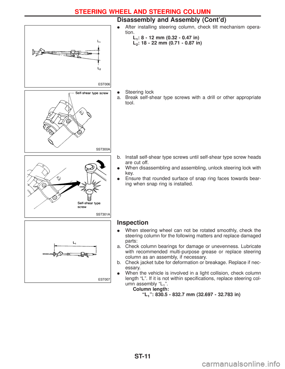
IAfter installing steering column, check tilt mechanism opera-
tion.
L
1:8-12mm(0.32 - 0.47 in)
L
2: 18 - 22 mm (0.71 - 0.87 in)
ISteering lock
a. Break self-shear type screws with a drill or other appropriate
tool.
b. Install self-shear type screws until self-shear type screw heads
are cut off.
IWhen disassembling and assembling, unlock steering lock with
key.
IEnsure that rounded surface of snap ring faces towards bear-
ing when snap ring is installed.
Inspection
IWhen steering wheel can not be rotated smoothly, check the
steering column for the following matters and replace damaged
parts:
a. Check column bearings for damage or unevenness. Lubricate
with recommended multi-purpose grease or replace steering
column as an assembly, if necessary.
b. Check jacket tube for deformation or breakage. Replace if nec-
essary.
IWhen the vehicle is involved in a light collision, check column
length ªLº. If it is not within specifications, replace steering col-
umn assembly ªL
1º.
Column length:
ªL
1º: 830.5 - 832.7 mm (32.697 - 32.783 in)
EST006
SST300A
SST301A
EST007
STEERING WHEEL AND STEERING COLUMN
Disassembly and Assembly (Cont'd)
ST-11