Page 174 of 1767
6. Remove servo piston spring retainer, return spring C and pis-
ton stem from band servo piston.
7. Remove E-ring from band servo piston.
8. Remove servo cushion spring retainer from band servo piston.
9. Remove D-rings from band servo piston.
10. Remove O-rings from servo piston retainer.
INSPECTION
Pistons, retainers and piston stem
ICheck frictional surfaces for abnormal wear or damage.
Return springs
ICheck for deformation or damage. Measure free length and
outer diameter.
Inspection standard:
Refer to SDS, AT-198.
SAT912A
SAT913A
SAT914A
SAT915A
SAT916AA
REPAIR FOR COMPONENT PARTS
Band Servo Piston Assembly (Cont'd)
AT-172
Page 180 of 1767
2. Install accumulator piston.
a. Install O-rings onto accumulator piston.
IApply ATF to O-rings.
Accumulator piston O-rings
Unit: mm (in)
AccumulatorqAqBqCqD
Small diameter end 29 (1.14) 32 (1.26) 45 (1.77) 29 (1.14)
Large diameter end 45 (1.77) 50 (1.97) 50 (1.97) 45 (1.77)
b. Install return spring for accumulator A onto transmission case.
Free length of return spring:
Refer to SDS, AT-197.
c. Install accumulator pistonsq
A,qB,qCandqD.
IApply ATF to transmission case.
3. Install band servo piston.
a. Install return springs onto servo piston.
b. Install band servo piston onto transmission case.
IApply ATF to O-ring of band servo piston and transmission
case.
c. Install gasket for band servo onto transmission case.
SAT523GA
SAT938A
SAT939AA
SAT941A
SAT942A
ASSEMBLY
Assembly (1) (Cont'd)
AT-178
Page 193 of 1767
c. While holding anchor end pin, tighten lock nut.
8. Install terminal cord assembly.
a. Install O-ring on terminal cord assembly.
IApply petroleum jelly to O-ring.
b. Compress terminal cord assembly stopper and install terminal
cord assembly on transmission case.
9. Install control valve assembly.
a. Install accumulator piston return springsq
B,qCandqD.
Free length of return springs:
Refer to SDS, AT-197.
b. Install manual valve on control valve.
IApply ATF to manual valve.
c. Place control valve assembly on transmission case. Connect
solenoid connector for upper body.
d. Install connector clip.
SAT002B
SAT115B
SAT004BA
SAT005B
SAT006B
ASSEMBLY
Assembly (2) (Cont'd)
AT-191
Page 199 of 1767

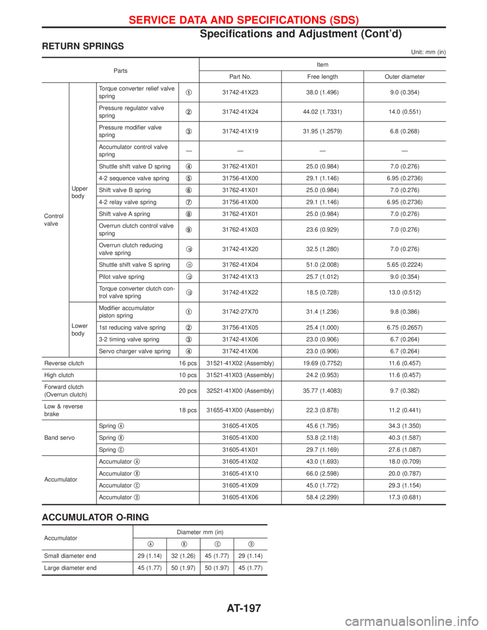
RETURN SPRINGSUnit: mm (in)
PartsItem
Part No. Free length Outer diameter
Control
valveUpper
bodyTorque converter relief valve
springq
131742-41X23 38.0 (1.496) 9.0 (0.354)
Pressure regulator valve
springq
231742-41X24 44.02 (1.7331) 14.0 (0.551)
Pressure modifier valve
springq
331742-41X19 31.95 (1.2579) 6.8 (0.268)
Accumulator control valve
springÐÐÐÐ
Shuttle shift valve D springq
431762-41X01 25.0 (0.984) 7.0 (0.276)
4-2 sequence valve springq
531756-41X00 29.1 (1.146) 6.95 (0.2736)
Shift valve B springq
631762-41X01 25.0 (0.984) 7.0 (0.276)
4-2 relay valve springq
731756-41X00 29.1 (1.146) 6.95 (0.2736)
Shift valve A springq
831762-41X01 25.0 (0.984) 7.0 (0.276)
Overrun clutch control valve
springq
931762-41X03 23.6 (0.929) 7.0 (0.276)
Overrun clutch reducing
valve springq
1031742-41X20 32.5 (1.280) 7.0 (0.276)
Shuttle shift valve S springq
1131762-41X04 51.0 (2.008) 5.65 (0.2224)
Pilot valve springq
1231742-41X13 25.7 (1.012) 9.0 (0.354)
Torque converter clutch con-
trol valve springq
1331742-41X22 18.5 (0.728) 13.0 (0.512)
Lower
bodyModifier accumulator
piston springq
131742-27X70 31.4 (1.236) 9.8 (0.386)
1st reducing valve springq
231756-41X05 25.4 (1.000) 6.75 (0.2657)
3-2 timing valve springq
331742-41X06 23.0 (0.906) 6.7 (0.264)
Servo charger valve springq
431742-41X06 23.0 (0.906) 6.7 (0.264)
Reverse clutch 16 pcs 31521-41X02 (Assembly) 19.69 (0.7752) 11.6 (0.457)
High clutch 10 pcs 31521-41X03 (Assembly) 24.2 (0.953) 11.6 (0.457)
Forward clutch
(Overrun clutch)20 pcs 32521-41X00 (Assembly) 35.77 (1.4083) 9.7 (0.382)
Low & reverse
brake18 pcs 31655-41X00 (Assembly) 22.3 (0.878) 11.2 (0.441)
Band servoSpringq
A31605-41X05 45.6 (1.795) 34.3 (1.350)
Springq
B31605-41X00 53.8 (2.118) 40.3 (1.587)
Springq
C31605-41X01 29.7 (1.169) 27.6 (1.087)
AccumulatorAccumulatorq
A31605-41X02 43.0 (1.693) 18.0 (0.709)
Accumulatorq
B31605-41X10 66.0 (2.598) 20.0 (0.787)
Accumulatorq
C31605-41X09 45.0 (1.772) 29.3 (1.154)
Accumulatorq
D31605-41X06 58.4 (2.299) 17.3 (0.681)
ACCUMULATOR O-RING
AccumulatorDiameter mm (in)
qAqBqCqD
Small diameter end 29 (1.14) 32 (1.26) 45 (1.77) 29 (1.14)
Large diameter end 45 (1.77) 50 (1.97) 50 (1.97) 45 (1.77)
SERVICE DATA AND SPECIFICATIONS (SDS)
Specifications and Adjustment (Cont'd)
AT-197
Page 214 of 1767
Inspection and Adjustment
CAUTION:
ICheck level in brake fluid reservoir.
IRefill with recommended brake fluid ªDOT 4º.
INever reuse drained brake fluid.
IBe careful not to splash brake fluid on painted areas; it
may cause paint damage. If brake fluid is splashed on
painted areas wash it away with water immediately. DO
NOT RUB IT OFF.
1. Before adjusting load sensing valve spring length, check for
proper installation and abnormal wear of brake pads and
shoes.
2. Remove the air bleeder from the wheel caliper, and install a
pressure gauge (A) to the bleed valve hole.
3. Bleed the air from the front brake piping.
4. Remove the air bleed valve from the rear wheel cylinder, and
install a pressure gauge (B) to the bleed valve hole.
EBR019
EBR020
EBR021
LOAD SENSING VALVE
BR-12
Page 215 of 1767

5. Bleed the air from the rear brake piping.
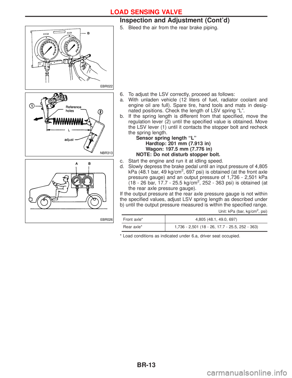
6. To adjust the LSV correctly, proceed as follows:
a. With unladen vehicle (12 liters of fuel, radiator coolant and
engine oil are full). Spare tire, hand tools and mats in desig-
nated positions. Check the length of LSV spring ªLº.
b. If the spring length is different from that specified, move the
regulation lever (2) until the specified value is obtained. Move
the LSV lever (1) until it contacts the stopper bolt and recheck
the spring length.
Sensor spring length ªLº
Hardtop: 201 mm (7.913 in)
Wagon: 197.5 mm (7.776 in)
NOTE: Do not disturb stopper bolt.
c. Start the engine and run it at idling speed.
d. Slowly depress the brake pedal until an input pressure of 4,805
kPa (48.1 bar, 49 kg/cm
2, 697 psi) is obtained (at the front axle
pressure gauge) and an output pressure of 1,736 - 2,501 kPa
(18 - 26 bar, 17.7 - 25.5 kg/cm
2, 252 - 363 psi) is obtained (at
the rear axle pressure gauge).
If the output pressure at the rear axle pressure gauge is not within
the specified values, adjust LSV spring length as described under
b) until the output pressure measured is within the specified range.
Unit: kPa (bar, kg/cm2, psi)
Front axle* 4,805 (48.1, 49.0, 697)
Rear axle* 1,736 - 2,501 (18 - 26, 17.7 - 25.5, 252 - 363)
* Load conditions as indicated under 6.a, driver seat occupied.
EBR022
NBR313
EBR026
LOAD SENSING VALVE
Inspection and Adjustment (Cont'd)
BR-13
Page 219 of 1767

Removal and Installation
Inspection
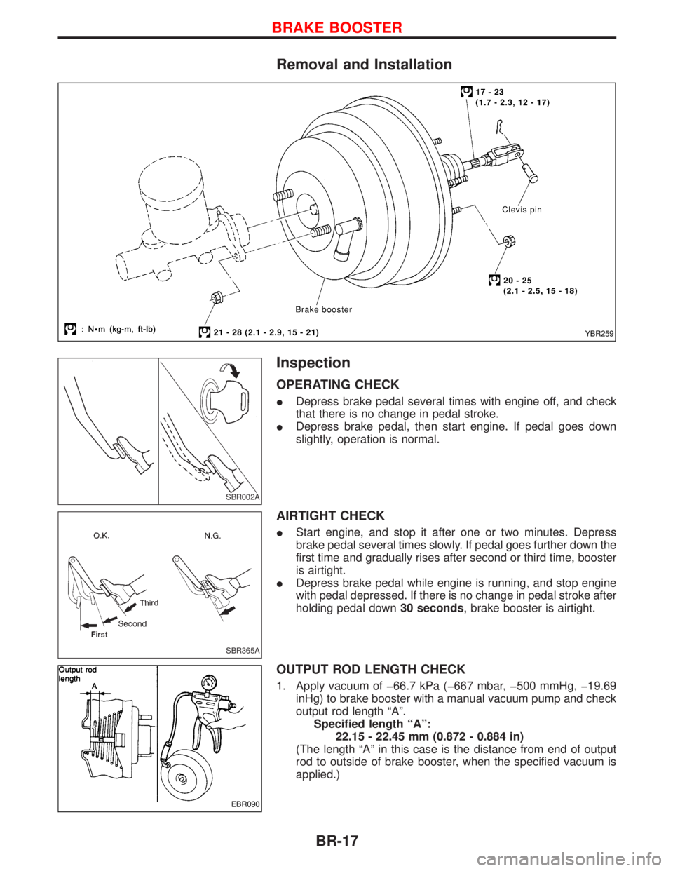
OPERATING CHECK
IDepress brake pedal several times with engine off, and check
that there is no change in pedal stroke.
IDepress brake pedal, then start engine. If pedal goes down
slightly, operation is normal.
AIRTIGHT CHECK
IStart engine, and stop it after one or two minutes. Depress
brake pedal several times slowly. If pedal goes further down the
first time and gradually rises after second or third time, booster
is airtight.
IDepress brake pedal while engine is running, and stop engine
with pedal depressed. If there is no change in pedal stroke after
holding pedal down30 seconds, brake booster is airtight.
OUTPUT ROD LENGTH CHECK
1. Apply vacuum of þ66.7 kPa (þ667 mbar, þ500 mmHg, þ19.69
inHg) to brake booster with a manual vacuum pump and check
output rod length ªAº.
Specified length ªAº:
22.15 - 22.45 mm (0.872 - 0.884 in)
(The length ªAº in this case is the distance from end of output
rod to outside of brake booster, when the specified vacuum is
applied.)
YBR259
SBR002A
SBR365A
EBR090
BRAKE BOOSTER
BR-17
Page 220 of 1767

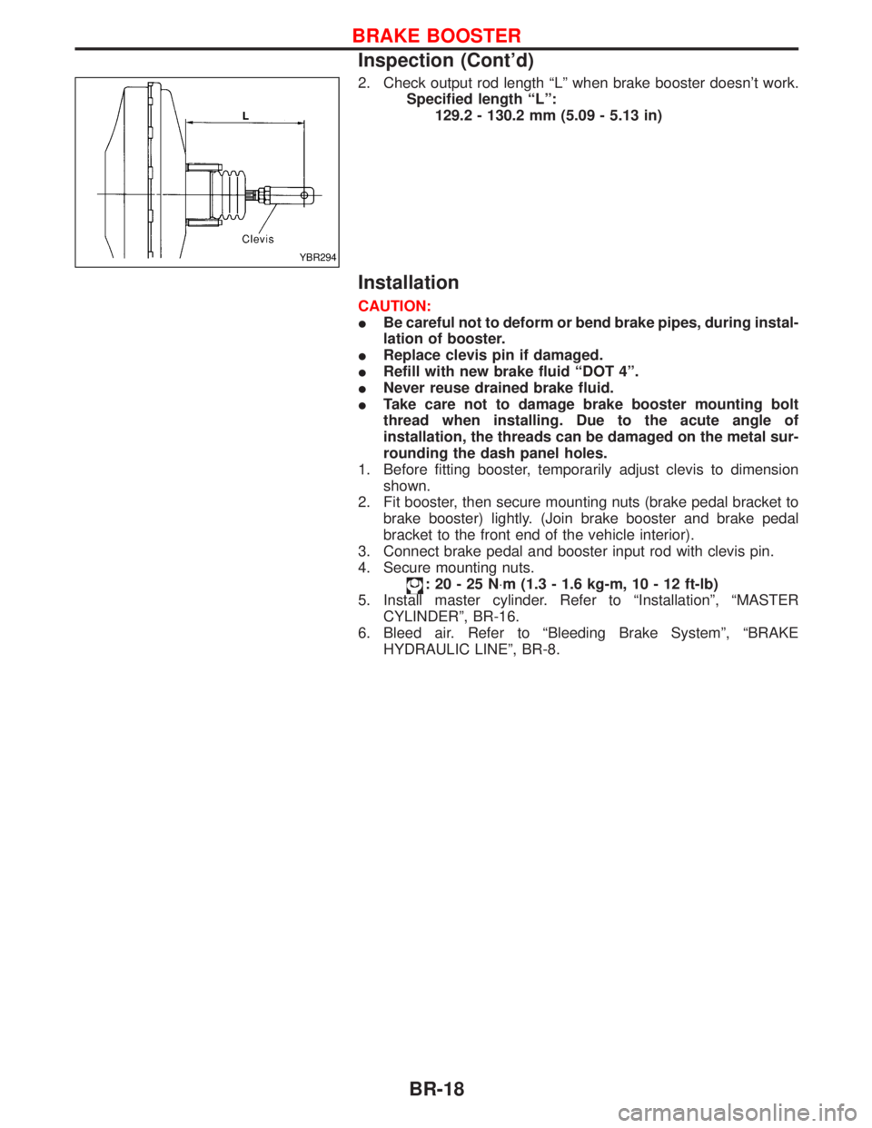
2. Check output rod length ªLº when brake booster doesn't work.
Specified length ªLº:
129.2 - 130.2 mm (5.09 - 5.13 in)
Installation
CAUTION:
IBe careful not to deform or bend brake pipes, during instal-
lation of booster.
IReplace clevis pin if damaged.
IRefill with new brake fluid ªDOT 4º.
INever reuse drained brake fluid.
ITake care not to damage brake booster mounting bolt
thread when installing. Due to the acute angle of
installation, the threads can be damaged on the metal sur-
rounding the dash panel holes.
1. Before fitting booster, temporarily adjust clevis to dimension
shown.
2. Fit booster, then secure mounting nuts (brake pedal bracket to
brake booster) lightly. (Join brake booster and brake pedal
bracket to the front end of the vehicle interior).
3. Connect brake pedal and booster input rod with clevis pin.
4. Secure mounting nuts.
:20-25N×m (1.3 - 1.6 kg-m, 10 - 12 ft-lb)
5. Install master cylinder. Refer to ªInstallationº, ªMASTER
CYLINDERº, BR-16.
6. Bleed air. Refer to ªBleeding Brake Systemº, ªBRAKE
HYDRAULIC LINEº, BR-8.
YBR294
BRAKE BOOSTER
Inspection (Cont'd)
BR-18