Page 1290 of 1767
Make sure that snap ring and anchor arm are properly
installed.
6. Tighten anchor arm adjusting nut to attain dimension ªLº.
Standard length ªLº:
77 mm (3.03 in)
7. Bounce vehicle with tires on ground (Unladen) to eliminate
friction of suspension.
8. Measure vehicle posture ªHº.
H = A þ B mm (in) ªUnladenº
Refer to SDS, FA-39.
(1) Exercise the front suspension by bouncing the front of the
vehicle 4 or 5 times to ensure that the vehicle is in a neutral
height attitude.
(2) Measure vehicle posture ... Dimension ªHº.
(Refer to SDS, FA-39.)
SFA185A
YFA014
YFA015
SFA965
NFA015
FRONT SUSPENSION
Torsion Bar (Cont'd)
FA-32
Page 1296 of 1767

General Specifications
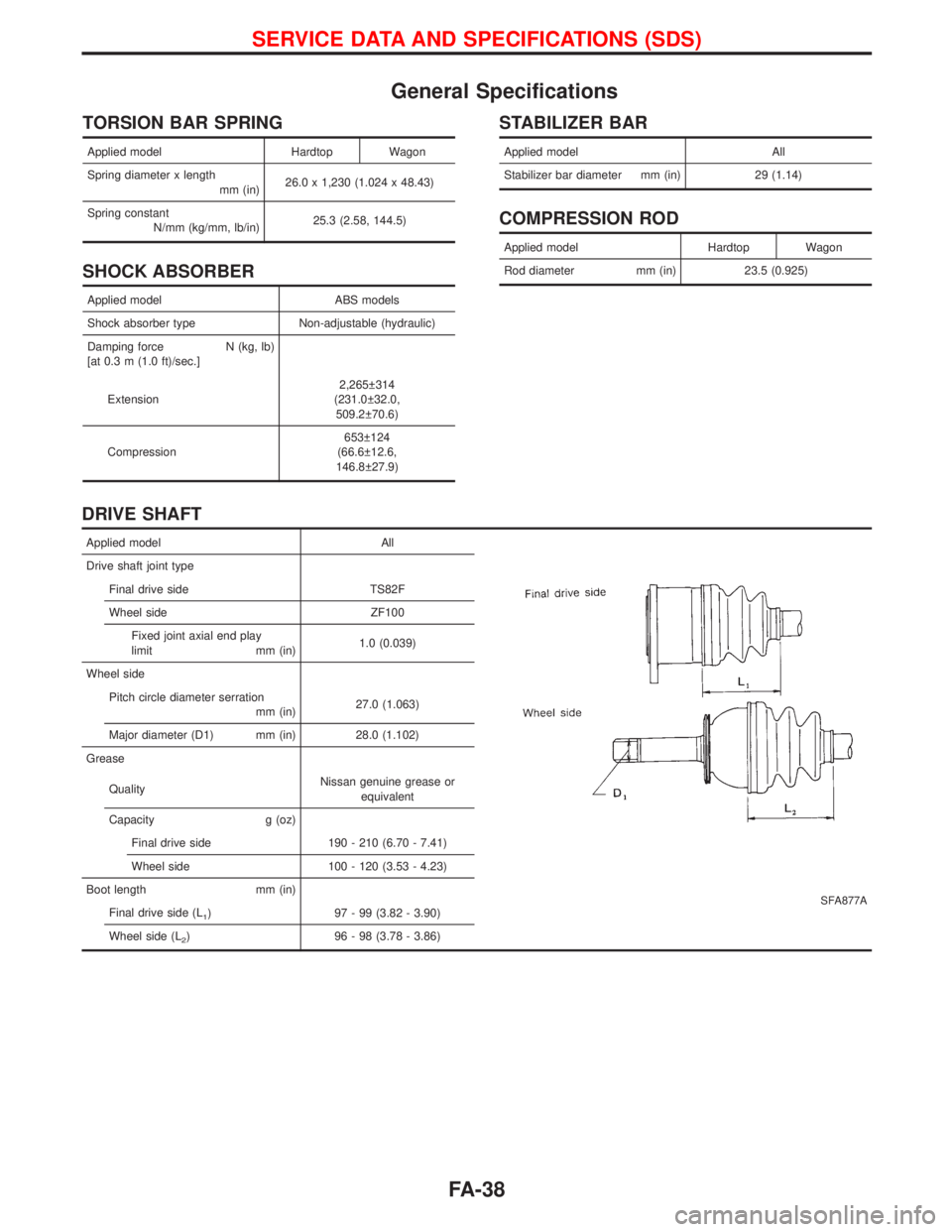
TORSION BAR SPRING
Applied model Hardtop Wagon
Spring diameter x length
mm (in)26.0 x 1,230 (1.024 x 48.43)
Spring constant
N/mm (kg/mm, lb/in)25.3 (2.58, 144.5)
SHOCK ABSORBER
Applied model ABS models
Shock absorber type Non-adjustable (hydraulic)
Damping force N (kg, lb)
[at 0.3 m (1.0 ft)/sec.]
Extension2,265 314
(231.0 32.0,
509.2 70.6)
Compression653 124
(66.6 12.6,
146.8 27.9)
STABILIZER BAR
Applied model All
Stabilizer bar diameter mm (in) 29 (1.14)
COMPRESSION ROD
Applied model Hardtop Wagon
Rod diameter mm (in) 23.5 (0.925)
DRIVE SHAFT
Applied model All
SFA877A
Drive shaft joint type
Final drive side TS82F
Wheel side ZF100
Fixed joint axial end play
limit mm (in)1.0 (0.039)
Wheel side
Pitch circle diameter serration
mm (in)27.0 (1.063)
Major diameter (D1) mm (in) 28.0 (1.102)
Grease
QualityNissan genuine grease or
equivalent
Capacity g (oz)
Final drive side 190 - 210 (6.70 - 7.41)
Wheel side 100 - 120 (3.53 - 4.23)
Boot length mm (in)
Final drive side (L
1) 97 - 99 (3.82 - 3.90)
Wheel side (L
2) 96 - 98 (3.78 - 3.86)
SERVICE DATA AND SPECIFICATIONS (SDS)
FA-38
Page 1346 of 1767
Dimensions
Unit: mm (in)
Hardtop Wagon
Overall length 4,242 (167.0) 4,722 (185.9)
Overall width (*) 1,755 (69.1) 1,755 (69.1)
Overall height 1,805 (71.1) 1,810 (71.3)
Front tread 1,455 (57.3) 1,455 (57.3)
Rear tread 1,430 (56.3) 1,430 (56.3)
Wheelbase 2,450 (96.5) 2,650 (104.3)
Ground clearance 210 (8.3) 205 (8.1)
Front overhang 837 (33.0) 837 (33.0)
Rear overhang
bumper 835 (32.9) 1,115 (43.9)
spare wheel 955 (37.6) 1,235 (48.6)
(*): without mirrors
Wheels and Tires
Road wheel size 16 x 7J
Offset [mm (in)] 25 (0.98)
Tire size 235/70 R16
IDENTIFICATION INFORMATION
GI-31
Page 1387 of 1767

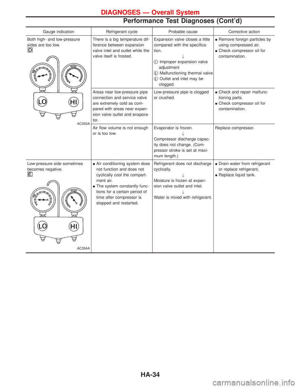
Gauge indication Refrigerant cycle Probable cause Corrective action
Both high- and low-pressure
sides are too low.
AC353A
There is a big temperature dif-
ference between expansion
valve inlet and outlet while the
valve itself is frosted.Expansion valve closes a little
compared with the specifica-
tion.
"
q
1Improper expansion valve
adjustment
q
2Malfunctioning thermal valve
q
3Outlet and inlet may be
clogged.IRemove foreign particles by
using compressed air.
ICheck compressor oil for
contamination.
Areas near low-pressure pipe
connection and service valve
are extremely cold as com-
pared with areas near expan-
sion valve outlet and evapora-
tor.Low-pressure pipe is clogged
or crushed.ICheck and repair malfunc-
tioning parts.
ICheck compressor oil for
contamination.
Air flow volume is not enough
or is too low.Evaporator is frozen.
"
Compressor discharge capac-
ity does not change. (Com-
pressor stroke is set at maxi-
mum length.)Replace compressor.
Low-pressure side sometimes
becomes negative.
AC354A
IAir conditioning system does
not function and does not
cyclically cool the compart-
ment air.
IThe system constantly func-
tions for a certain period of
time after compressor is
stopped and restarted.Refrigerant does not discharge
cyclically.
"
Moisture is frozen at expan-
sion valve outlet and inlet.
"
Water is mixed with refrigerant.IDrain water from refrigerant
or replace refrigerant.
IReplace liquid tank.
DIAGNOSES Ð Overall System
Performance Test Diagnoses (Cont'd)
HA-34
Page 1433 of 1767
OIL FILTER
The oil filter is an element type. Refer to ªChanging Oil Filterº in MA
section.
Oil Cooler
REMOVAL AND INSTALLATION
1. Drain engine oil and coolant.
Remove catalyst and turbocharger. Refer to ªCATALYST AND
TURBOCHARGERº in EM section.
2. Remove bolts A to C then remove oil cooler assembly.
IDo not remove ªDº nuts when removing oil cooler assem-
bly.
Bolt length:
A: 20 mm (0.79 in)
B: 45 mm (1.77 in)
C: 65 mm (2.56 in)
3. Installation is in reverse order of removal.
IDo not spill coolant on the drive belt.
INSPECTION
1. Check oil cooler for cracks.
2. Check oil cooler for clogging by blowing through coolant inlet.
If necessary, replace oil cooler assembly.
YLC030
JLC381B
ENGINE LUBRICATION SYSTEMZD
Oil Jet (Cont'd)
LC-8
Page 1488 of 1767

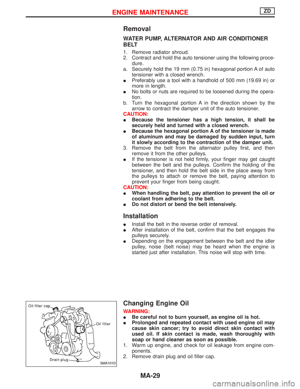
Removal
WATER PUMP, ALTERNATOR AND AIR CONDITIONER
BELT
1. Remove radiator shroud.
2. Contract and hold the auto tensioner using the following proce-
dure.
a. Securely hold the 19 mm (0.75 in) hexagonal portion A of auto
tensioner with a closed wrench.
IPreferably use a tool with a handhold of 500 mm (19.69 in) or
more in length.
INo bolts or nuts are required to be loosened during the opera-
tion.
b. Turn the hexagonal portion A in the direction shown by the
arrow to contract the damper unit of the auto tensioner.
CAUTION:
IBecause the tensioner has a high tension, it shall be
securely held and turned with a closed wrench.
IBecause the hexagonal portion A of the tensioner is made
of aluminum and may be damaged by sudden input, turn
it slowly according to the contraction of the damper unit.
3. Remove the belt from the alternator pulley first, and then
remove it from the other pulleys.
IIf the tensioner is not held firmly, your finger may get caught
between the belt and the pulleys. Confirm the holding of the
tensioner, and then hold the belt side in the place away from
the pulleys to attach or remove the belt, paying attention to
prevent your finger from being caught.
CAUTION:
IWhen handling the belt, pay attention to prevent the oil or
coolant from adhering to the belt.
IDo not distort or bend the belt intensively.
Installation
IInstall the belt in the reverse order of removal.
IAfter installation of the belt, confirm that the belt engages the
pulleys securely.
IDepending on the engagement between the belt and the idler
pulley, noise (belt noise) may be heard when the engine is
started just after installation. This noise will stop with time.
Changing Engine Oil
WARNING:
IBe careful not to burn yourself, as engine oil is hot.
IProlonged and repeated contact with used engine oil may
cause skin cancer; try to avoid direct skin contact with
used oil. If skin contact is made, wash thoroughly with
soap or hand cleaner as soon as possible.
1. Warm up engine, and check for oil leakage from engine com-
ponents.
2. Remove drain plug and oil filler cap.
SMA101D
ENGINE MAINTENANCEZD
MA-29
Page 1517 of 1767
Installation
Transmission has to be installed as a unit together with transfer
box.
Install transmission assembly as follows:
IApply sealant as below:
Bolt No. Tightening torque N×m (kg-m, ft-lb)Bolt length ªLº -
mm (in)
1 39 - 49 (4.0 - 5.0, 29 - 36) 57 (2.244)
2 18 - 22 (1.9 - 2.2, 14 - 16) 11 (0.433)
3 29 - 39 (3.0 - 4.0, 22 - 29) 100 (3.94)
NMT002
NMT027
REMOVAL AND INSTALLATIONFS5R30A
MT-8
Page 1590 of 1767

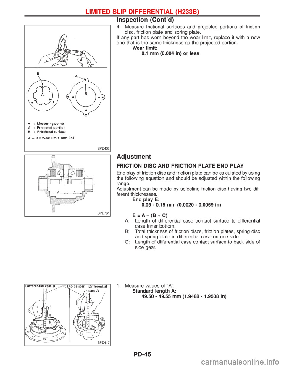
4. Measure frictional surfaces and projected portions of friction
disc, friction plate and spring plate.
If any part has worn beyond the wear limit, replace it with a new
one that is the same thickness as the projected portion.
Wear limit:
0.1 mm (0.004 in) or less
Adjustment
FRICTION DISC AND FRICTION PLATE END PLAY
End play of friction disc and friction plate can be calculated by using
the following equation and should be adjusted within the following
range.
Adjustment can be made by selecting friction disc having two dif-
ferent thicknesses.
End play E:
0.05 - 0.15 mm (0.0020 - 0.0059 in)
E=Aþ(B+C)
A: Length of differential case contact surface to differential
case inner bottom.
B: Total thickness of friction discs, friction plates, spring disc
and spring plate in differential case on one side.
C: Length of differential case contact surface to back side of
side gear.
1. Measure values of ªAº.
Standard length A:
49.50 - 49.55 mm (1.9488 - 1.9508 in)
SPD403
SPD761
SPD417
LIMITED SLIP DIFFERENTIAL (H233B)
Inspection (Cont'd)
PD-45