Page 222 of 1767
CAUTION:
When installing vacuum hoses, pay attention to the following
points.
IDo not apply any oil or lubricants to vacuum hose and
check valve.
IInsert vacuum tube into vacuum hose over a length of min.
24 mm (0.94 in) as shown.
Take care to main vacuum hoses in their original direction and
position.
YBR292
SBR225B
VACUUM HOSE
Removal and Installation (Cont'd)
BR-20
Page 286 of 1767
General Specifications
Applied modelWagon (LWB) Hard Top (SWB) Wagon (LWB) Hard Top (SWB)
Without ABS With ABS
Front brakeLD28VA
Brake model
Cylinder bore diameter
mm (in)43 (1.69)
Pad mm (in)
length x width x thickness144.85 x 48.5 x 15.5
(5.70 x 1.90 x 0.61)
Rotor outer mm (in)
diameter x thickness27.7 x 26.1
(10.91 x 1.02)
Drum brakeLT28
Brake model
Cylinder bore diameter
mm (in)23.8 (0.94) 22.0 (0.87) 20.6 (0.81)
Lining mm (in)
Length x width x thickness
Leading 111 x 55 x 8.95 (4.37 x 2.17 x 0.35)
Trailing 114 x 55 x 3.95 (4.49 x 2.17 x 0.16)
Drum inner mm (in)
Diameter280 (11.02)
Master cylinder mm (in)
Cylinder bore diameter 25.4 (1.0)
Control valve
Valve model Load Sensing Valve Ð
Split point [kPa (bar, kg/cm
2, psi)] x
reducing ratioVariable x 0.23 Variable x 0.15 Ð
Brake booster
Booster model Lucas LSC 115 (8²+9²)
Diaphragm diameter
mm (in)Primary: 203.2 (8)
Secondary: 228.6 (9)
Specified brake fluidDOT 4
SERVICE DATA AND SPECIFICATIONS (SDS)
BR-84
Page 337 of 1767
Alignment
IAll dimensions indicated in figures are actual ones.
IWhen using a tracking gauge, adjust both pointers to equal length. Then check the pointers and gauge
itself to make sure there is no free play.
IWhen a measuring tape is used, check to be sure there is no elongation, twisting or bending.
IMeasurements should be taken at the center of the mounting holes.
IAn asterisk (*) following the value at the measuring point indicates that the measuring point on the other
side is symmetrically the same value.
IThe coordinates of the measurement points are the distances measured from the standard line of ªXº, ªYº
and ªZº.
YBT089
BODY (ALIGNMENT)
BT-49
Page 657 of 1767
Special Service Tools
Tool number
Tool nameDescription
KV11229352
Measuring device
q
1KV11229350
Holder
q
2KV11229360
Nut
q
3KV11229370
Pin
q
4KV11254410
Dial gauge
NT570
Measuring set length of plunger spring
ST16540000
Pulley holder
NT628
Removing injection pump drive gear
a: 68 mm (2.68 in)
b: 8 mm (0.31 in)
KV11289004
Nozzle cleaning kit
q
1KV11290012
Box
q
2KV11290110
Brush
q
3KV11290122
Nozzle oil sump scraper
q
4KV11290140
Nozzle needle tip cleaner
q
5KV11290150
Nozzle seat scraper
q
6KV11290210
Nozzle holder
q
7KV11290220
Nozzle hole cleaning
needle
NT296
KV11290632
Nozzle oil sump scraper
NT294
KV11292010
Nozzle centering device
NT293
PRECAUTIONS AND PREPARATIONTD27Ti
EC-295
Page 1169 of 1767

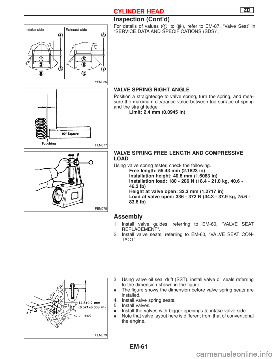
For details of values (q1toq10), refer to EM-87, ªValve Seatº in
ªSERVICE DATA AND SPECIFICATIONS (SDS)º.
VALVE SPRING RIGHT ANGLE
Position a straightedge to valve spring, turn the spring, and mea-
sure the maximum clearance value between top surface of spring
and the straightedge
Limit: 2.4 mm (0.0945 in)
VALVE SPRING FREE LENGTH AND COMPRESSIVE
LOAD
Using valve spring tester, check the following.
Free length: 55.43 mm (2.1823 in)
Installation height: 40.8 mm (1.6063 in)
Installation load: 180 - 206 N (18.4 - 21.0 kg, 40.6 -
46.3 lb)
Height at valve open: 32.3 mm (1.2717 in)
Load at valve open: 336 - 372 N (34.3 - 37.9 kg, 75.6 -
83.6 lb)
Assembly
1. Install valve guides, referring to EM-60, ªVALVE SEAT
REPLACEMENTº.
2. Install valve seats, referring to EM-60, ªVALVE SEAT CON-
TACTº.
3. Using valve oil seal drift (SST), install valve oil seals referring
to the dimension shown in the figure.
IThe figure shows the dimension before valve spring seats are
installed.
4. Install valve spring seats.
5. Install valves.
IInstall the valves with bigger openings to intake valve side.
INote that valve layout here is different from that of conventional
the engine.
YEM035
FEM077
FEM078
FEM079
CYLINDER HEADZD
Inspection (Cont'd)
EM-61
Page 1188 of 1767

Assembly
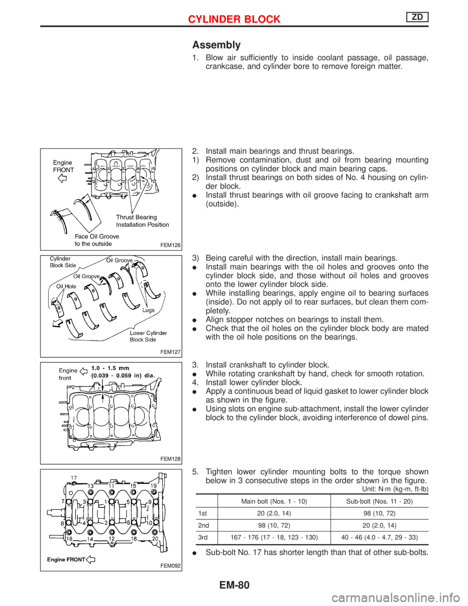
1. Blow air sufficiently to inside coolant passage, oil passage,
crankcase, and cylinder bore to remove foreign matter.
2. Install main bearings and thrust bearings.
1) Remove contamination, dust and oil from bearing mounting
positions on cylinder block and main bearing caps.
2) Install thrust bearings on both sides of No. 4 housing on cylin-
der block.
IInstall thrust bearings with oil groove facing to crankshaft arm
(outside).
3) Being careful with the direction, install main bearings.
IInstall main bearings with the oil holes and grooves onto the
cylinder block side, and those without oil holes and grooves
onto the lower cylinder block side.
IWhile installing bearings, apply engine oil to bearing surfaces
(inside). Do not apply oil to rear surfaces, but clean them com-
pletely.
IAlign stopper notches on bearings to install them.
ICheck that the oil holes on the cylinder block body are mated
with the oil hole positions on the bearings.
3. Install crankshaft to cylinder block.
IWhile rotating crankshaft by hand, check for smooth rotation.
4. Install lower cylinder block.
IApply a continuous bead of liquid gasket to lower cylinder block
as shown in the figure.
IUsing slots on engine sub-attachment, install the lower cylinder
block to the cylinder block, avoiding interference of dowel pins.
5. Tighten lower cylinder mounting bolts to the torque shown
below in 3 consecutive steps in the order shown in the figure.
Unit: N×m (kg-m, ft-lb)
Main bolt (Nos. 1 - 10) Sub-bolt (Nos. 11 - 20)
1st 20 (2.0, 14) 98 (10, 72)
2nd 98 (10, 72) 20 (2.0, 14)
3rd 167 - 176 (17 - 18, 123 - 130) 40 - 46 (4.0 - 4.7, 29 - 33)
ISub-bolt No. 17 has shorter length than that of other sub-bolts.
FEM126
FEM127
FEM128
FEM092
CYLINDER BLOCKZD
EM-80
Page 1190 of 1767

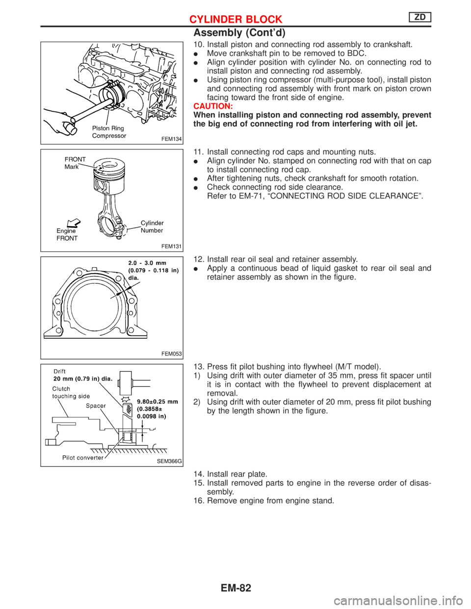
10. Install piston and connecting rod assembly to crankshaft.
IMove crankshaft pin to be removed to BDC.
IAlign cylinder position with cylinder No. on connecting rod to
install piston and connecting rod assembly.
IUsing piston ring compressor (multi-purpose tool), install piston
and connecting rod assembly with front mark on piston crown
facing toward the front side of engine.
CAUTION:
When installing piston and connecting rod assembly, prevent
the big end of connecting rod from interfering with oil jet.
11. Install connecting rod caps and mounting nuts.
IAlign cylinder No. stamped on connecting rod with that on cap
to install connecting rod cap.
IAfter tightening nuts, check crankshaft for smooth rotation.
ICheck connecting rod side clearance.
Refer to EM-71, ªCONNECTING ROD SIDE CLEARANCEº.
12. Install rear oil seal and retainer assembly.
IApply a continuous bead of liquid gasket to rear oil seal and
retainer assembly as shown in the figure.
13. Press fit pilot bushing into flywheel (M/T model).
1) Using drift with outer diameter of 35 mm, press fit spacer until
it is in contact with the flywheel to prevent displacement at
removal.
2) Using drift with outer diameter of 20 mm, press fit pilot bushing
by the length shown in the figure.
14. Install rear plate.
15. Install removed parts to engine in the reverse order of disas-
sembly.
16. Remove engine from engine stand.
FEM134
FEM131
FEM053
SEM366G
CYLINDER BLOCKZD
Assembly (Cont'd)
EM-82
Page 1193 of 1767
Valve head diameter ªDºIntake 31.9 - 32.1 (1.256 - 1.264)
Exhaust 29.9 - 30.1 (1.177 - 1.185)
Valve length ªLºIntake 113.5 (4.4685)
Exhaust 113.5 (4.4685)
Valve stem diameter ªdºIntake 6.962 - 6.977 (0.2741 - 0.2747)
Exhaust 6.945 - 6.960 (0.2734 - 0.2740)
Valve seat angle ªaºIntake
45É00¢- 45É30¢
Exhaust
Valve margin ªTºIntake 1.5 (0.059)
Exhaust 1.5 (0.059)
Valve stem end surface grinding limitLess than 0.2 (0.008)
VALVE CLEARANCE
Unit: mm (in)
Cold
Intake0.30 - 0.40 (0.0118 - 0.0157)
Exhaust0.30 - 0.40 (0.0118 - 0.0157)
*: Approximately 80ÉC (176ÉF)
AVAILABLE SHIMS
Thickness mm (in) Identification mark
2.35 (0.0925) 2.35
2.40 (0.0945) 2.40
2.45 (0.0965) 2.45
2.50 (0.0984) 2.50
2.55 (0.1004) 2.55
2.60 (0.1024) 2.60
2.65 (0.1043) 2.65
2.70 (0.1063) 2.70
2.75 (0.1083) 2.75
2.80 (0.1102) 2.80
2.85 (0.1122) 2.85
2.90 (0.1142) 2.90
2.95 (0.1161) 2.95
3.00 (0.1181) 3.00
3.05 (0.1201) 3.05
SEM252G
SERVICE DATA AND SPECIFICATIONS (SDS)ZD
Valve (Cont'd)
EM-85