2002 NISSAN TERRANO check engine
[x] Cancel search: check enginePage 1338 of 1767
Incident Simulation Tests
INTRODUCTION
Sometimes the symptom is not present when the vehicle is brought in for service. If possible, re-create the
conditions present at the time of the incident. Doing so may help avoid a No Trouble Found Diagnosis. The
following section illustrates ways to simulate the conditions/environment under which the owner experiences
an electrical incident.
The section is broken into the six following topics:
IVehicle vibration
IHeat sensitive
IFreezing
IWater intrusion
IElectrical load
ICold or hot start up
Get a thorough description of the incident from the customer. It is important for simulating the conditions of
the problem.
VEHICLE VIBRATION
The problem may occur or become worse while driving on a rough road or when engine is vibrating (idle with
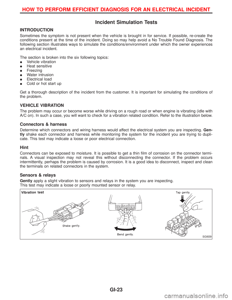
A/C on). In such a case, you will want to check for a vibration related condition. Refer to the illustration below.
Connectors & harness
Determine which connectors and wiring harness would affect the electrical system you are inspecting.Gen-
tlyshake each connector and harness while monitoring the system for the incident you are trying to dupli-
cate. This test may indicate a loose or poor electrical connection.
Hint
Connectors can be exposed to moisture. It is possible to get a thin film of corrosion on the connector termi-
nals. A visual inspection may not reveal this without disconnecting the connector. If the problem occurs
intermittently, perhaps the problem is caused by corrosion. It is a good idea to disconnect, inspect and clean
the terminals on related connectors in the system.
Sensors & relays
Gentlyapply a slight vibration to sensors and relays in the system you are inspecting.
This test may indicate a loose or poorly mounted sensor or relay.
SGI839
HOW TO PERFORM EFFICIENT DIAGNOSIS FOR AN ELECTRICAL INCIDENT
GI-23
Page 1339 of 1767
Engine compartment
There are several reasons a vehicle or engine vibration could
cause an electrical complaint. Some of the things to check for are:
IConnectors not fully seated.
IWiring harness not long enough and is being stressed due to
engine vibrations or rocking.
IWires laying across brackets or moving components.
ILoose, dirty or corroded ground wires.
IWires routed too close to hot components.
To inspect components under the hood, start by verifying the integ-
rity of ground connections. (Refer to GROUND INSPECTION
described later.) First check that the system is properly grounded.
Then check for loose connection bygently shakingthe wiring or
components as previously explained. Using the wiring diagrams
inspect the wiring for continuity.
Behind the instrument panel
An improperly routed or improperly clamped harness can become
pinched during accessory installation. Vehicle vibration can aggra-
vate a harness which is routed along a bracket or near a screw.
Under seating areas
An unclamped or loose harness can cause wiring to be pinched by
seat components (such as slide guides) during vehicle vibration. If
the wiring runs under seating areas, inspect wire routing for pos-
sible damage or pinching.
HEAT SENSITIVE
The owner's problem may occur during hot weather or after car has
sat for a short time. In such cases you will want to check for a heat
sensitive condition.
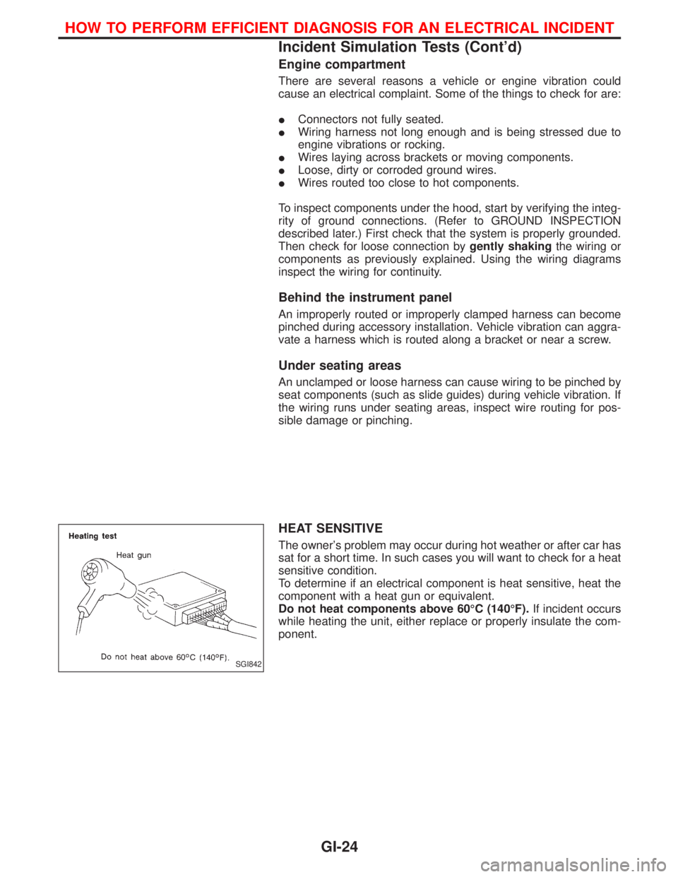
To determine if an electrical component is heat sensitive, heat the
component with a heat gun or equivalent.
Do not heat components above 60ÉC (140ÉF).If incident occurs
while heating the unit, either replace or properly insulate the com-
ponent.
SGI842
HOW TO PERFORM EFFICIENT DIAGNOSIS FOR AN ELECTRICAL INCIDENT
Incident Simulation Tests (Cont'd)
GI-24
Page 1340 of 1767
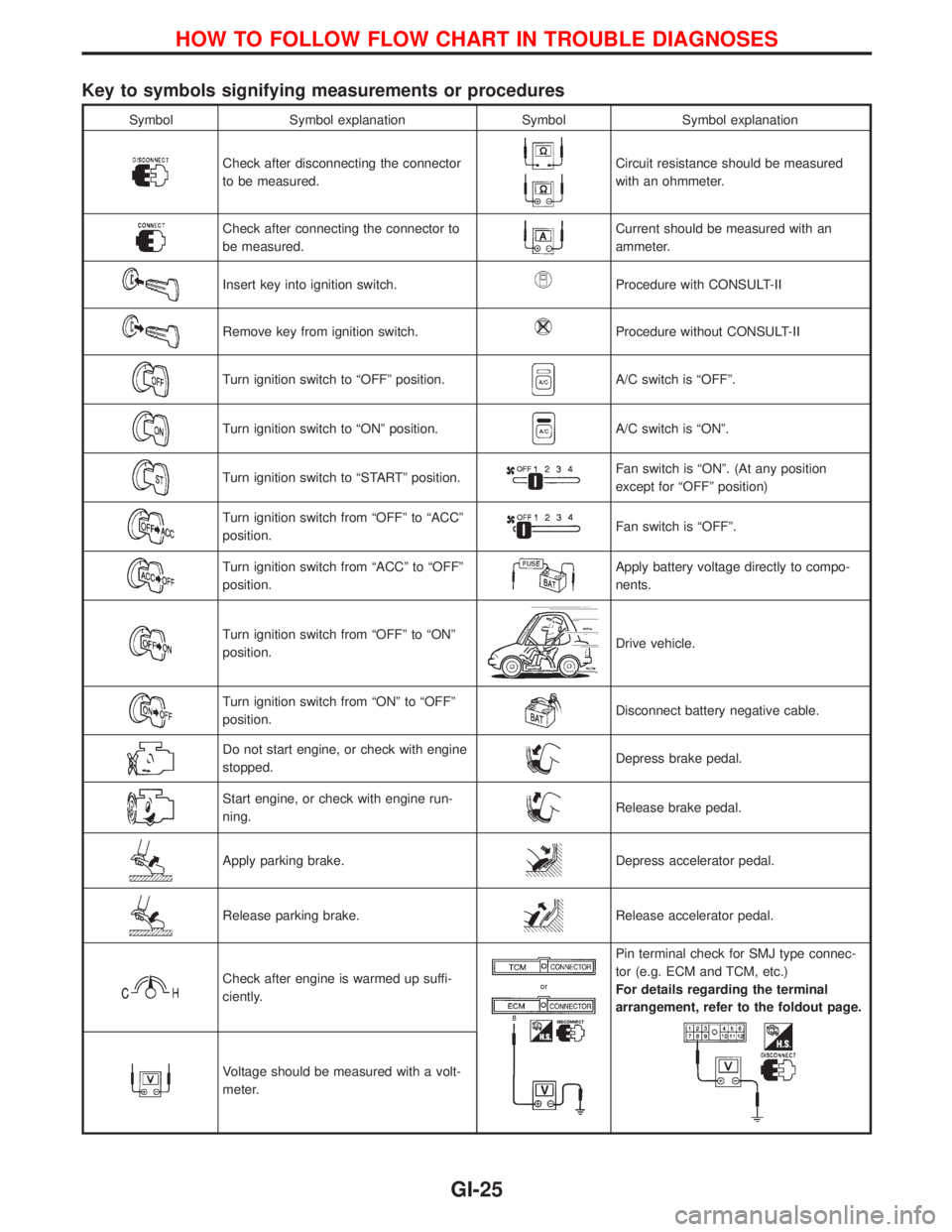
Key to symbols signifying measurements or procedures
Symbol Symbol explanation Symbol Symbol explanation
Check after disconnecting the connector
to be measured.Circuit resistance should be measured
with an ohmmeter.
Check after connecting the connector to
be measured.Current should be measured with an
ammeter.
Insert key into ignition switch.Procedure with CONSULT-II
Remove key from ignition switch.Procedure without CONSULT-II
Turn ignition switch to ªOFFº position.A/C switch is ªOFFº.
Turn ignition switch to ªONº position.A/C switch is ªONº.
Turn ignition switch to ªSTARTº position.Fan switch is ªONº. (At any position
except for ªOFFº position)
Turn ignition switch from ªOFFº to ªACCº
position.Fan switch is ªOFFº.
Turn ignition switch from ªACCº to ªOFFº
position.Apply battery voltage directly to compo-
nents.
Turn ignition switch from ªOFFº to ªONº
position.Drive vehicle.
Turn ignition switch from ªONº to ªOFFº
position.Disconnect battery negative cable.
Do not start engine, or check with engine
stopped.Depress brake pedal.
Start engine, or check with engine run-
ning.Release brake pedal.
Apply parking brake.Depress accelerator pedal.
Release parking brake.Release accelerator pedal.
Check after engine is warmed up suffi-
ciently.
Pin terminal check for SMJ type connec-
tor (e.g. ECM and TCM, etc.)
For details regarding the terminal
arrangement, refer to the foldout page.
Voltage should be measured with a volt-
meter.
HOW TO FOLLOW FLOW CHART IN TROUBLE DIAGNOSES
GI-25
Page 1341 of 1767
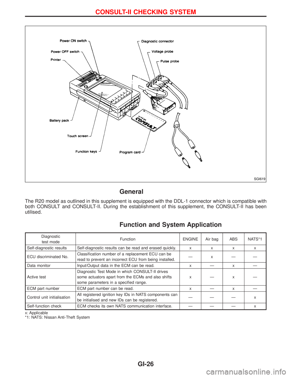
General
The R20 model as outlined in this supplement is equipped with the DDL-1 connector which is compatible with
both CONSULT and CONSULT-II. During the establishment of this supplement, the CONSULT-II has been
utilised.
Function and System Application
Diagnostic
test modeFunction ENGINE Air bag ABS NATS*1
Self-diagnostic results Self-diagnostic results can be read and erased quickly.xxxx
ECU discriminated No.Classification number of a replacement ECU can be
read to prevent an incorrect ECU from being installed.ÐxÐÐ
Data monitor Input/Output data in the ECM can be read.xÐxÐ
Active testDiagnostic Test Mode in which CONSULT-II drives
some actuators apart from the ECMs and also shifts
some parameters in a specified range.xÐxÐ
ECM part number ECM part number can be read.xÐxÐ
Control unit initialisationAll registered ignition key IDs in NATS components can
be initialised and new IDs can be registered.ÐÐÐ x
Self-function check ECM checks its own NATS communication interface. Ð Ð Ð x
x: Applicable
*1: NATS: Nissan Anti-Theft System
SGI619
CONSULT-II CHECKING SYSTEM
GI-26
Page 1351 of 1767
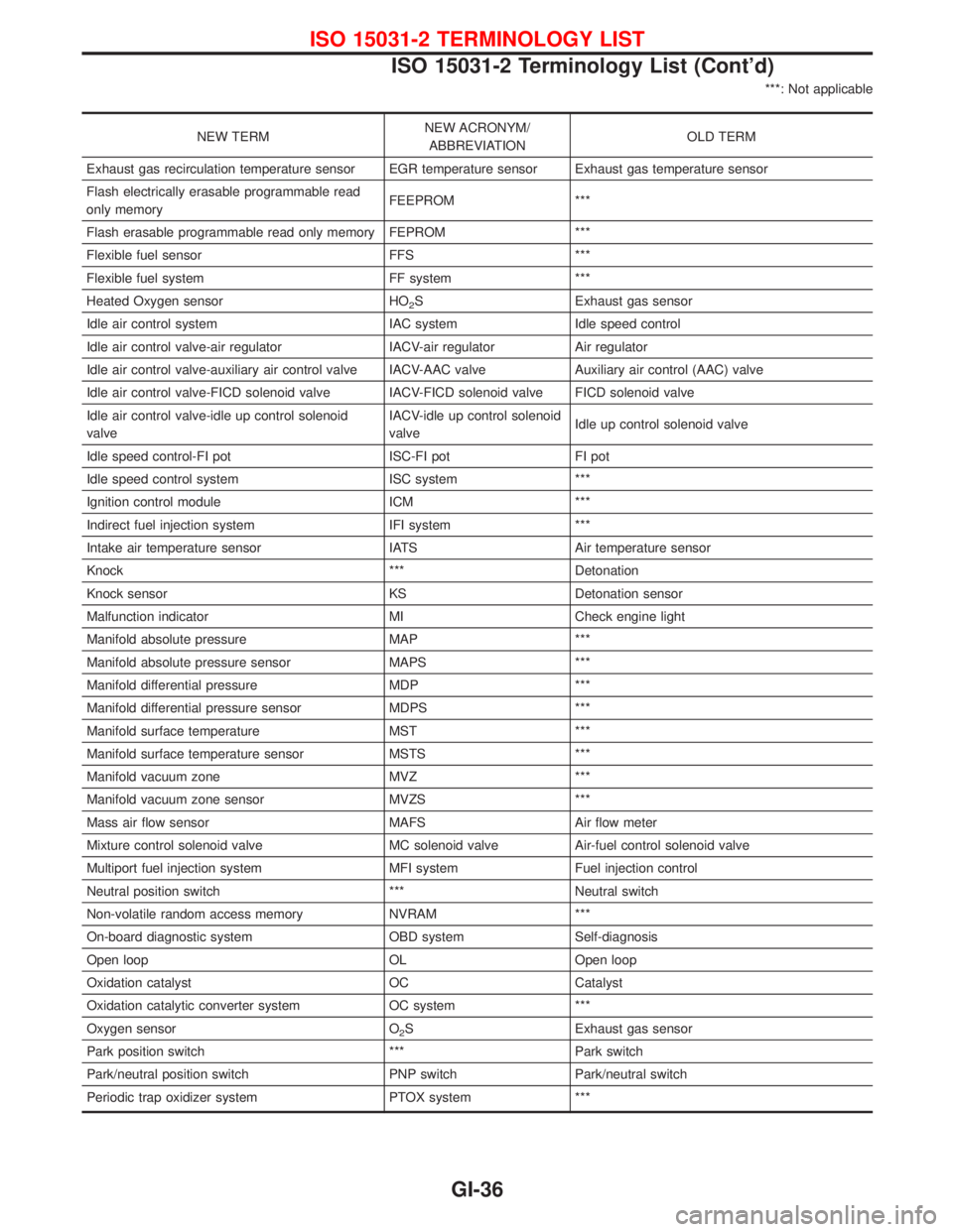
***: Not applicable
NEW TERMNEW ACRONYM/
ABBREVIATIONOLD TERM
Exhaust gas recirculation temperature sensor EGR temperature sensor Exhaust gas temperature sensor
Flash electrically erasable programmable read
only memoryFEEPROM ***
Flash erasable programmable read only memory FEPROM ***
Flexible fuel sensor FFS ***
Flexible fuel system FF system ***
Heated Oxygen sensor HO
2S Exhaust gas sensor
Idle air control system IAC system Idle speed control
Idle air control valve-air regulator IACV-air regulator Air regulator
Idle air control valve-auxiliary air control valve IACV-AAC valve Auxiliary air control (AAC) valve
Idle air control valve-FICD solenoid valve IACV-FICD solenoid valve FICD solenoid valve
Idle air control valve-idle up control solenoid
valveIACV-idle up control solenoid
valveIdle up control solenoid valve
Idle speed control-FI pot ISC-FI pot FI pot
Idle speed control system ISC system ***
Ignition control module ICM ***
Indirect fuel injection system IFI system ***
Intake air temperature sensor IATS Air temperature sensor
Knock *** Detonation
Knock sensor KS Detonation sensor
Malfunction indicator MI Check engine light
Manifold absolute pressure MAP ***
Manifold absolute pressure sensor MAPS ***
Manifold differential pressure MDP ***
Manifold differential pressure sensor MDPS ***
Manifold surface temperature MST ***
Manifold surface temperature sensor MSTS ***
Manifold vacuum zone MVZ ***
Manifold vacuum zone sensor MVZS ***
Mass air flow sensor MAFS Air flow meter
Mixture control solenoid valve MC solenoid valve Air-fuel control solenoid valve
Multiport fuel injection system MFI system Fuel injection control
Neutral position switch *** Neutral switch
Non-volatile random access memory NVRAM ***
On-board diagnostic system OBD system Self-diagnosis
Open loop OL Open loop
Oxidation catalyst OC Catalyst
Oxidation catalytic converter system OC system ***
Oxygen sensor O
2S Exhaust gas sensor
Park position switch *** Park switch
Park/neutral position switch PNP switch Park/neutral switch
Periodic trap oxidizer system PTOX system ***
ISO 15031-2 TERMINOLOGY LIST
ISO 15031-2 Terminology List (Cont'd)
GI-36
Page 1358 of 1767
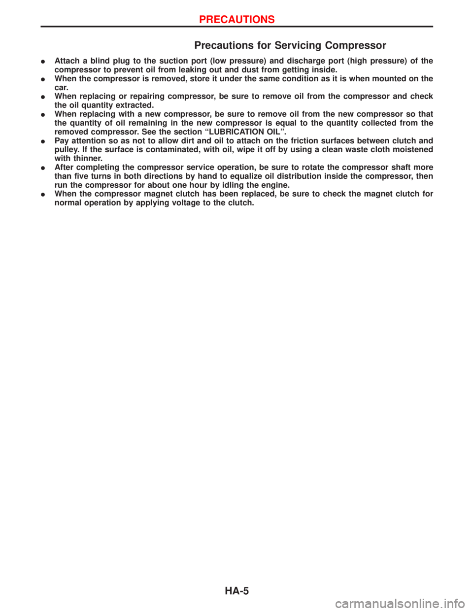
Precautions for Servicing Compressor
IAttach a blind plug to the suction port (low pressure) and discharge port (high pressure) of the
compressor to prevent oil from leaking out and dust from getting inside.
IWhen the compressor is removed, store it under the same condition as it is when mounted on the
car.
IWhen replacing or repairing compressor, be sure to remove oil from the compressor and check
the oil quantity extracted.
IWhen replacing with a new compressor, be sure to remove oil from the new compressor so that
the quantity of oil remaining in the new compressor is equal to the quantity collected from the
removed compressor. See the section ªLUBRICATION OILº.
IPay attention so as not to allow dirt and oil to attach on the friction surfaces between clutch and
pulley. If the surface is contaminated, with oil, wipe it off by using a clean waste cloth moistened
with thinner.
IAfter completing the compressor service operation, be sure to rotate the compressor shaft more
than five turns in both directions by hand to equalize oil distribution inside the compressor, then
run the compressor for about one hour by idling the engine.
IWhen the compressor magnet clutch has been replaced, be sure to check the magnet clutch for
normal operation by applying voltage to the clutch.
PRECAUTIONS
HA-5
Page 1369 of 1767
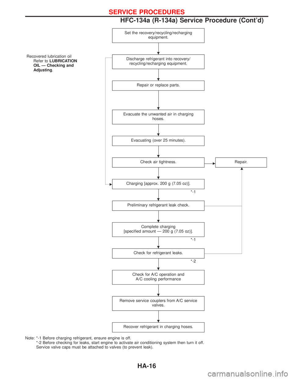
Set the recovery/recycling/recharging
equipment.
Recovered lubrication oil
Refer toLUBRICATION
OIL Ð Checking and
Adjusting.Discharge refrigerant into recovery/
recycling/recharging equipment.
Repair or replace parts.
Evacuate the unwanted air in charging
hoses.
Evacuating (over 25 minutes).
Check air tightness.ERepair.
G
ECharging [approx. 200 g (7.05 oz)].
*-1
Preliminary refrigerant leak check.
Complete charging
[specified amount Ð 200 g (7.05 oz)].
*-1
Check for refrigerant leaks.
*-2
Check for A/C operation and
A/C cooling performance
Remove service couplers from A/C service
valves.
Recover refrigerant in charging hoses.
Note: *-1 Before charging refrigerant, ensure engine is off.
*-2 Before checking for leaks, start engine to activate air conditioning system then turn it off.
Service valve caps must be attached to valves (to prevent leak).
H
H
H
H
H
H
H
H
H
H
H
H
SERVICE PROCEDURES
HFC-134a (R-134a) Service Procedure (Cont'd)
HA-16
Page 1375 of 1767
Lubrication Oil
Name: Nissan A/C System Oil Type R
Part number: KLH00-PAGR0
Maintenance of Oil Quantity in Compressor
The oil used to lubricate the compressor circulates through the
system with the refrigerant. Whenever any component of the sys-
tem is replaced or a large amount of gas leakage occurs, add oil
to the compressor to maintain the specified amount.
If oil quantity is not maintained properly, the following malfunctions
may result:
ILack of oil: May lead to a seized compressor
IExcessive oil: Inadequate cooling (thermal exchange impeded)
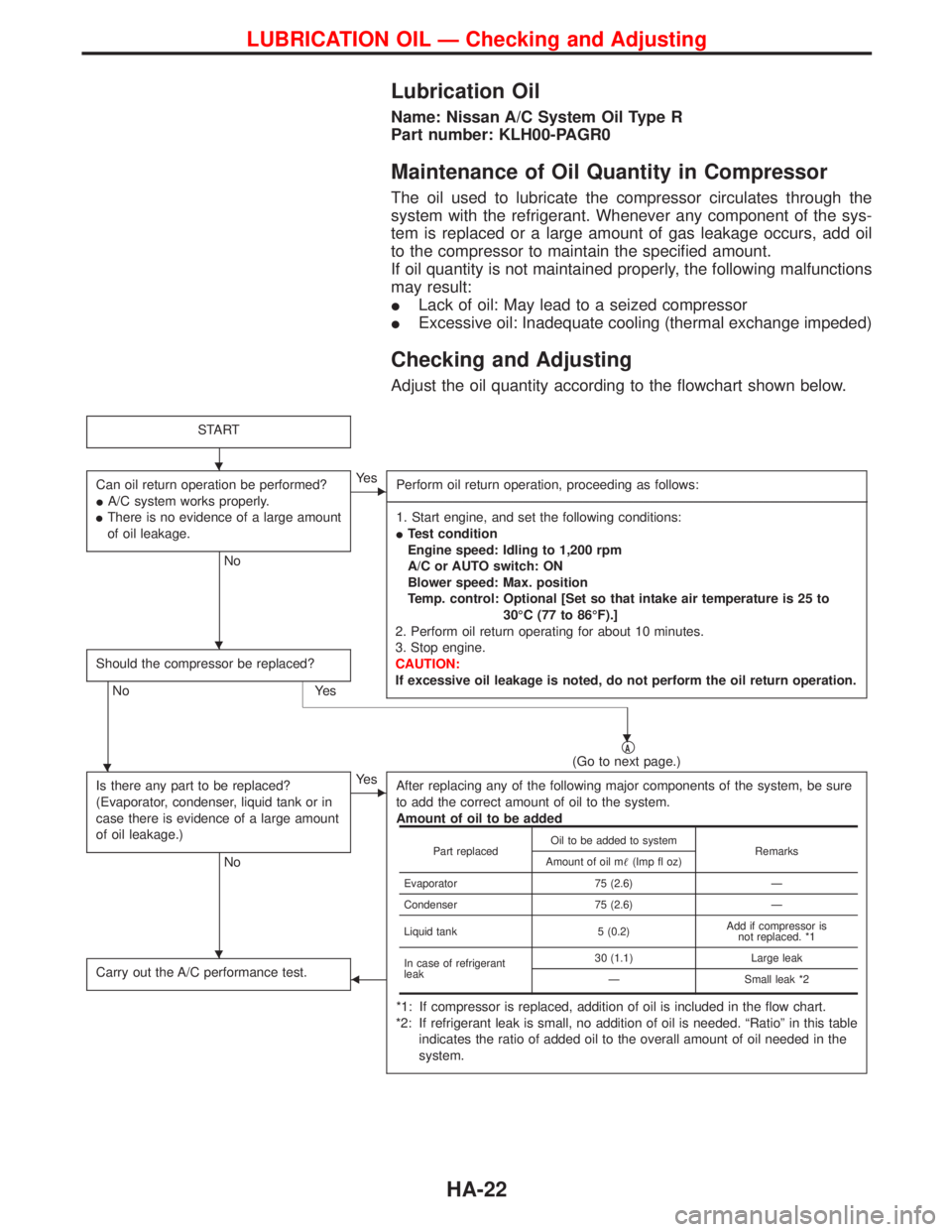
Checking and Adjusting
Adjust the oil quantity according to the flowchart shown below.
START
Can oil return operation be performed?
IA/C system works properly.
IThere is no evidence of a large amount
of oil leakage.
No
EYe s
Perform oil return operation, proceeding as follows:
-------------------------------------------------------------------------------------------------------------------------------------------------------------------------------------------------------------------------------------------------------------------------------------------------------------------------------------------------------------------------------------------------------------------------------------------------------------------------------------------------------------------------------------------------------------
1. Start engine, and set the following conditions:
ITest condition
Engine speed: Idling to 1,200 rpm
A/C or AUTO switch: ON
Blower speed: Max. position
Temp. control: Optional [Set so that intake air temperature is 25 to
30ÉC (77 to 86ÉF).]
2. Perform oil return operating for about 10 minutes.
3. Stop engine.
CAUTION:
If excessive oil leakage is noted, do not perform the oil return operation.
Should the compressor be replaced?
No Yes
qA(Go to next page.)
Is there any part to be replaced?
(Evaporator, condenser, liquid tank or in
case there is evidence of a large amount
of oil leakage.)
No
EYe s
After replacing any of the following major components of the system, be sure
to add the correct amount of oil to the system.
Amount of oil to be added
*1: If compressor is replaced, addition of oil is included in the flow chart.
*2: If refrigerant leak is small, no addition of oil is needed. ªRatioº in this table
indicates the ratio of added oil to the overall amount of oil needed in the
system.
Carry out the A/C performance test.F
Part replacedOil to be added to system
Remarks
Amount of oil m(Imp fl oz)
Evaporator 75 (2.6) Ð
Condenser 75 (2.6) Ð
Liquid tank 5 (0.2)Add if compressor is
not replaced. *1
In case of refrigerant
leak30 (1.1) Large leak
Ð Small leak *2
H
H
H
H
H
LUBRICATION OIL Ð Checking and Adjusting
HA-22