Page 1169 of 1767
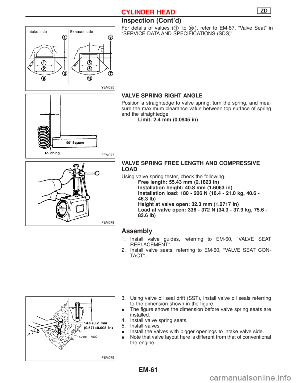
For details of values (q1toq10), refer to EM-87, ªValve Seatº in
ªSERVICE DATA AND SPECIFICATIONS (SDS)º.
VALVE SPRING RIGHT ANGLE
Position a straightedge to valve spring, turn the spring, and mea-
sure the maximum clearance value between top surface of spring
and the straightedge
Limit: 2.4 mm (0.0945 in)
VALVE SPRING FREE LENGTH AND COMPRESSIVE
LOAD
Using valve spring tester, check the following.
Free length: 55.43 mm (2.1823 in)
Installation height: 40.8 mm (1.6063 in)
Installation load: 180 - 206 N (18.4 - 21.0 kg, 40.6 -
46.3 lb)
Height at valve open: 32.3 mm (1.2717 in)
Load at valve open: 336 - 372 N (34.3 - 37.9 kg, 75.6 -
83.6 lb)
Assembly
1. Install valve guides, referring to EM-60, ªVALVE SEAT
REPLACEMENTº.
2. Install valve seats, referring to EM-60, ªVALVE SEAT CON-
TACTº.
3. Using valve oil seal drift (SST), install valve oil seals referring
to the dimension shown in the figure.
IThe figure shows the dimension before valve spring seats are
installed.
4. Install valve spring seats.
5. Install valves.
IInstall the valves with bigger openings to intake valve side.
INote that valve layout here is different from that of conventional
the engine.
YEM035
FEM077
FEM078
FEM079
CYLINDER HEADZD
Inspection (Cont'd)
EM-61
Page 1173 of 1767
21. Hook hoists to slingers to secure the position.
22. Remove installation nuts for left and right engine mount insula-
tors.
23. While adjusting position frequently, hoist and remove the
engine.
CAUTION:
IWhile performing operation, check that all necessary wires
and pipes are disconnected.
IAvoid interference with parts on the vehicle.
Installation
Install the engine in the reverse order of the removal procedure.
IKeep each mount insulator from oil adherence and damage.
IWhile keeping each mount insulator free from twisting, tighten
mounting bolts and nuts for the engine mount.
Inspection
IBefore starting the engine, check coolant level and grease
amount, and if necessary, refill them to the specified level.
IStart the engine, and check that there is no abnormal noise or
vibration.
IWarm up the engine to the sufficient temperature, and check
that there is no leakage of coolant, greases, fuel, or exhaust
gas.
YEM042
ENGINE REMOVALZD
Removal (Cont'd)
EM-65
Page 1178 of 1767
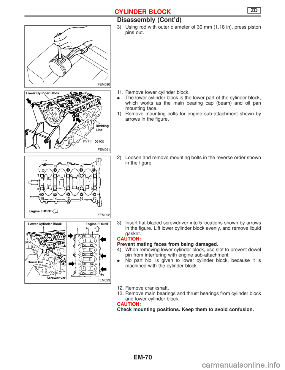
3) Using rod with outer diameter of 30 mm (1.18 in), press piston
pins out.
11. Remove lower cylinder block.
IThe lower cylinder block is the lower part of the cylinder block,
which works as the main bearing cap (beam) and oil pan
mounting face.
1) Remove mounting bolts for engine sub-attachment shown by
arrows in the figure.
2) Loosen and remove mounting bolts in the reverse order shown
in the figure.
3) Insert flat-bladed screwdriver into 5 locations shown by arrows
in the figure. Lift lower cylinder block evenly, and remove liquid
gasket.
CAUTION:
Prevent mating faces from being damaged.
4) When removing lower cylinder block, use slot to prevent dowel
pin from interfering with engine sub-attachment.
INo part No. is given to lower cylinder block, because it is
machined with the cylinder block.
12. Remove crankshaft.
13. Remove main bearings and thrust bearings from cylinder block
and lower cylinder block.
CAUTION:
Check mounting positions. Keep them to avoid confusion.
FEM090
FEM091
FEM092
FEM093
CYLINDER BLOCKZD
Disassembly (Cont'd)
EM-70
Page 1182 of 1767
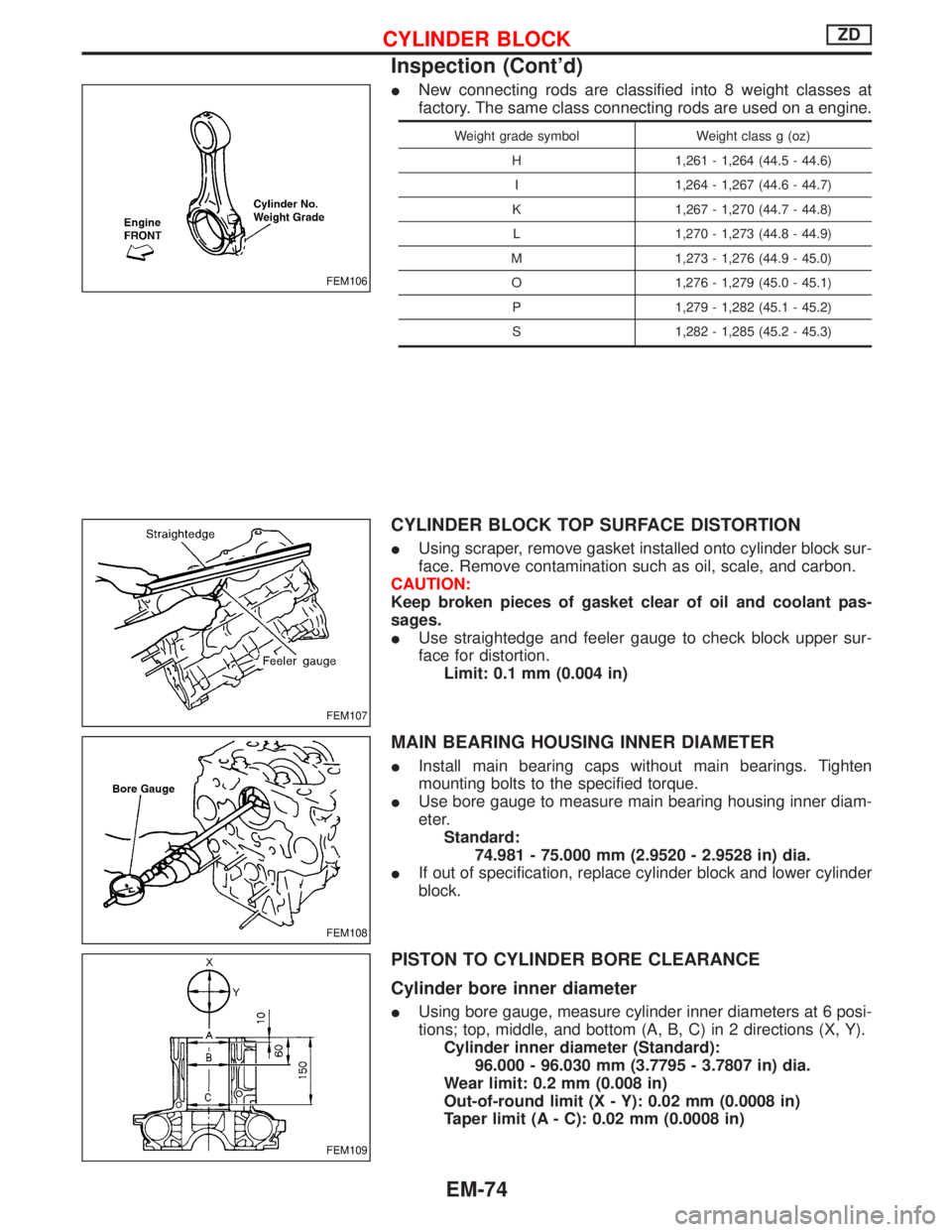
INew connecting rods are classified into 8 weight classes at
factory. The same class connecting rods are used on a engine.
Weight grade symbol Weight class g (oz)
H 1,261 - 1,264 (44.5 - 44.6)
I 1,264 - 1,267 (44.6 - 44.7)
K 1,267 - 1,270 (44.7 - 44.8)
L 1,270 - 1,273 (44.8 - 44.9)
M 1,273 - 1,276 (44.9 - 45.0)
O 1,276 - 1,279 (45.0 - 45.1)
P 1,279 - 1,282 (45.1 - 45.2)
S 1,282 - 1,285 (45.2 - 45.3)
CYLINDER BLOCK TOP SURFACE DISTORTION
IUsing scraper, remove gasket installed onto cylinder block sur-
face. Remove contamination such as oil, scale, and carbon.
CAUTION:
Keep broken pieces of gasket clear of oil and coolant pas-
sages.
IUse straightedge and feeler gauge to check block upper sur-
face for distortion.
Limit: 0.1 mm (0.004 in)
MAIN BEARING HOUSING INNER DIAMETER
IInstall main bearing caps without main bearings. Tighten
mounting bolts to the specified torque.
IUse bore gauge to measure main bearing housing inner diam-
eter.
Standard:
74.981 - 75.000 mm (2.9520 - 2.9528 in) dia.
IIf out of specification, replace cylinder block and lower cylinder
block.
PISTON TO CYLINDER BORE CLEARANCE
Cylinder bore inner diameter
IUsing bore gauge, measure cylinder inner diameters at 6 posi-
tions; top, middle, and bottom (A, B, C) in 2 directions (X, Y).
Cylinder inner diameter (Standard):
96.000 - 96.030 mm (3.7795 - 3.7807 in) dia.
Wear limit: 0.2 mm (0.008 in)
Out-of-round limit (X - Y): 0.02 mm (0.0008 in)
Taper limit (A - C): 0.02 mm (0.0008 in)
FEM106
FEM107
FEM108
FEM109
CYLINDER BLOCKZD
Inspection (Cont'd)
EM-74
Page 1188 of 1767
Assembly
1. Blow air sufficiently to inside coolant passage, oil passage,
crankcase, and cylinder bore to remove foreign matter.
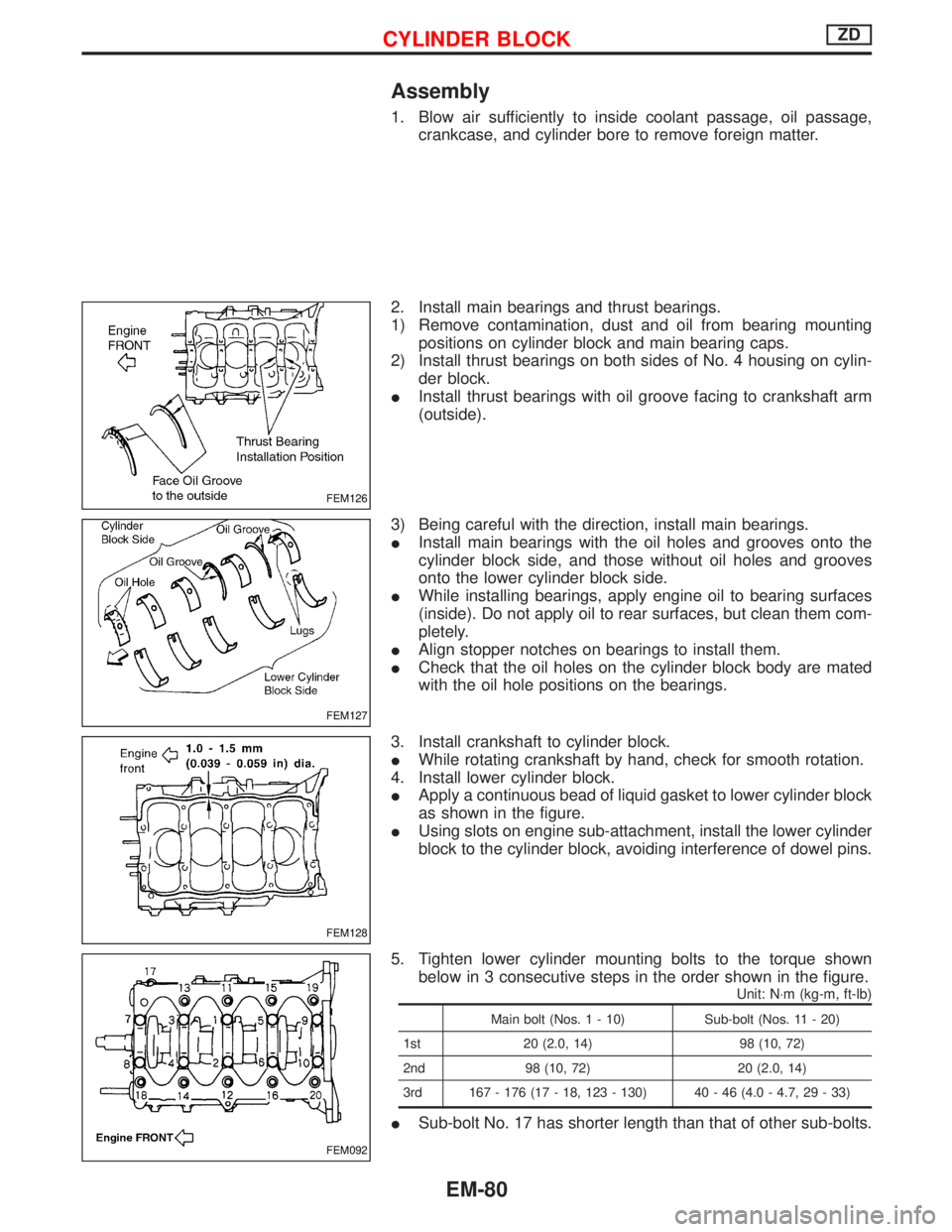
2. Install main bearings and thrust bearings.
1) Remove contamination, dust and oil from bearing mounting
positions on cylinder block and main bearing caps.
2) Install thrust bearings on both sides of No. 4 housing on cylin-
der block.
IInstall thrust bearings with oil groove facing to crankshaft arm
(outside).
3) Being careful with the direction, install main bearings.
IInstall main bearings with the oil holes and grooves onto the
cylinder block side, and those without oil holes and grooves
onto the lower cylinder block side.
IWhile installing bearings, apply engine oil to bearing surfaces
(inside). Do not apply oil to rear surfaces, but clean them com-
pletely.
IAlign stopper notches on bearings to install them.
ICheck that the oil holes on the cylinder block body are mated
with the oil hole positions on the bearings.
3. Install crankshaft to cylinder block.
IWhile rotating crankshaft by hand, check for smooth rotation.
4. Install lower cylinder block.
IApply a continuous bead of liquid gasket to lower cylinder block
as shown in the figure.
IUsing slots on engine sub-attachment, install the lower cylinder
block to the cylinder block, avoiding interference of dowel pins.
5. Tighten lower cylinder mounting bolts to the torque shown
below in 3 consecutive steps in the order shown in the figure.
Unit: N×m (kg-m, ft-lb)
Main bolt (Nos. 1 - 10) Sub-bolt (Nos. 11 - 20)
1st 20 (2.0, 14) 98 (10, 72)
2nd 98 (10, 72) 20 (2.0, 14)
3rd 167 - 176 (17 - 18, 123 - 130) 40 - 46 (4.0 - 4.7, 29 - 33)
ISub-bolt No. 17 has shorter length than that of other sub-bolts.
FEM126
FEM127
FEM128
FEM092
CYLINDER BLOCKZD
EM-80
Page 1189 of 1767
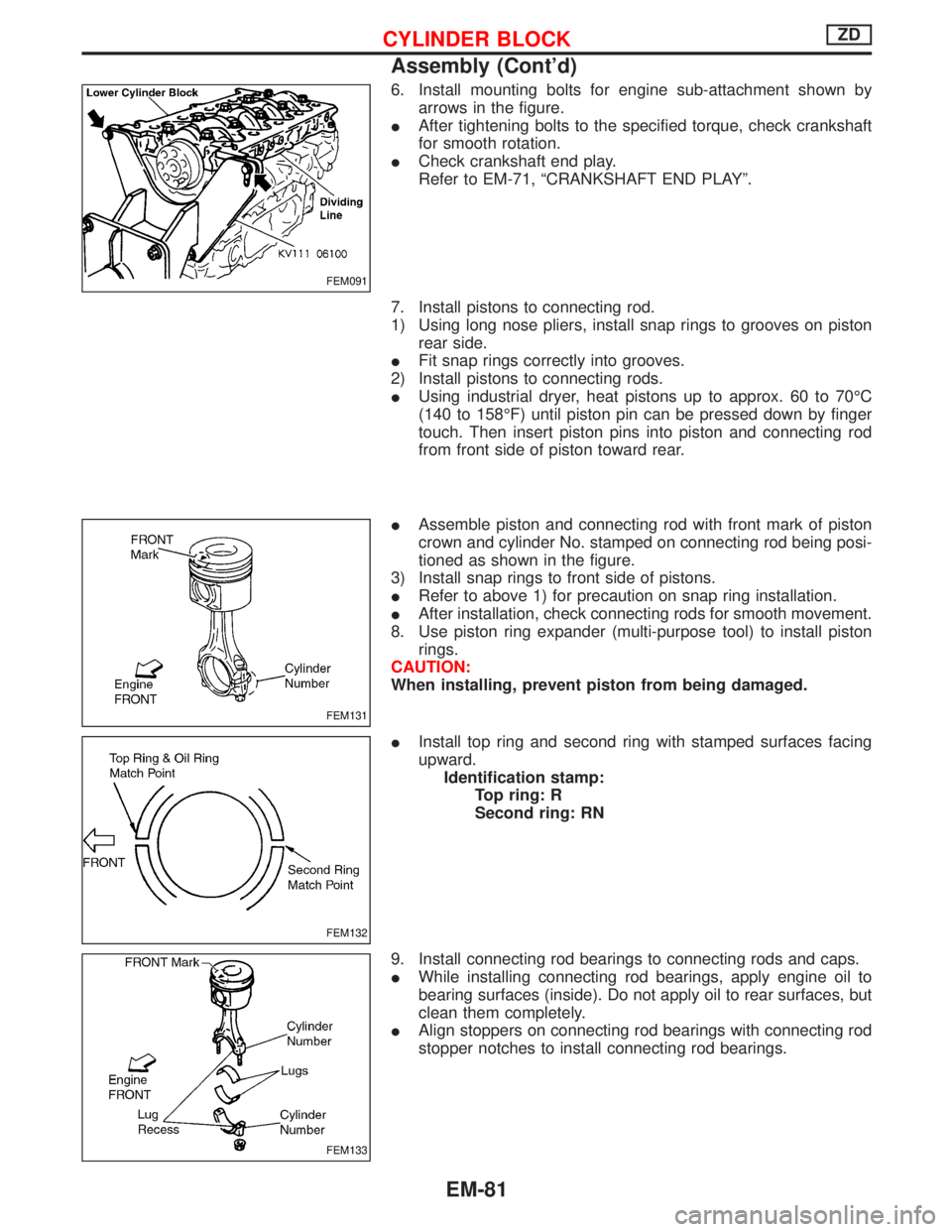
6. Install mounting bolts for engine sub-attachment shown by
arrows in the figure.
IAfter tightening bolts to the specified torque, check crankshaft
for smooth rotation.
ICheck crankshaft end play.
Refer to EM-71, ªCRANKSHAFT END PLAYº.
7. Install pistons to connecting rod.
1) Using long nose pliers, install snap rings to grooves on piston
rear side.
IFit snap rings correctly into grooves.
2) Install pistons to connecting rods.
IUsing industrial dryer, heat pistons up to approx. 60 to 70ÉC
(140 to 158ÉF) until piston pin can be pressed down by finger
touch. Then insert piston pins into piston and connecting rod
from front side of piston toward rear.
IAssemble piston and connecting rod with front mark of piston
crown and cylinder No. stamped on connecting rod being posi-
tioned as shown in the figure.
3) Install snap rings to front side of pistons.
IRefer to above 1) for precaution on snap ring installation.
IAfter installation, check connecting rods for smooth movement.
8. Use piston ring expander (multi-purpose tool) to install piston
rings.
CAUTION:
When installing, prevent piston from being damaged.
IInstall top ring and second ring with stamped surfaces facing
upward.
Identification stamp:
Top ring: R
Second ring: RN
9. Install connecting rod bearings to connecting rods and caps.
IWhile installing connecting rod bearings, apply engine oil to
bearing surfaces (inside). Do not apply oil to rear surfaces, but
clean them completely.
IAlign stoppers on connecting rod bearings with connecting rod
stopper notches to install connecting rod bearings.
FEM091
FEM131
FEM132
FEM133
CYLINDER BLOCKZD
Assembly (Cont'd)
EM-81
Page 1190 of 1767
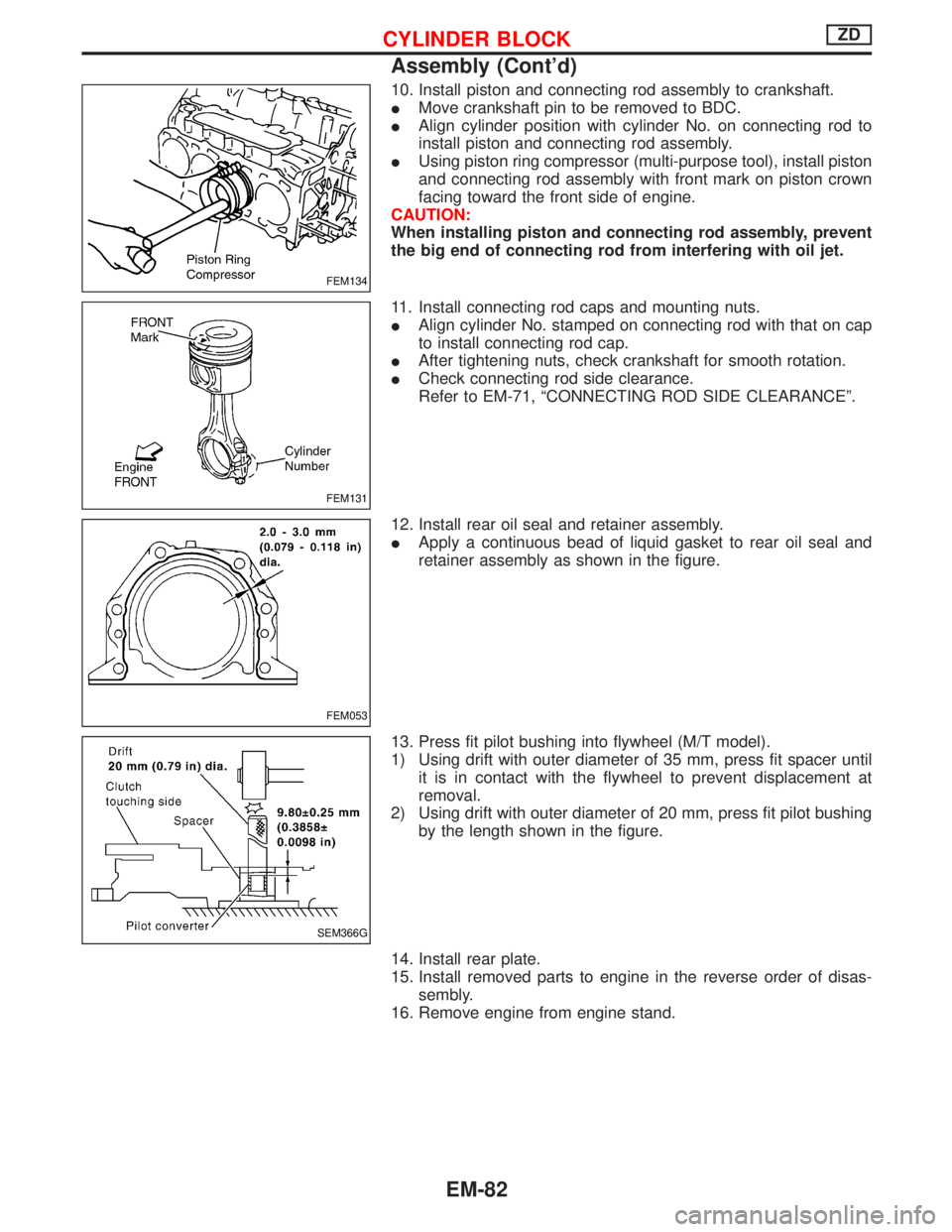
10. Install piston and connecting rod assembly to crankshaft.
IMove crankshaft pin to be removed to BDC.
IAlign cylinder position with cylinder No. on connecting rod to
install piston and connecting rod assembly.
IUsing piston ring compressor (multi-purpose tool), install piston
and connecting rod assembly with front mark on piston crown
facing toward the front side of engine.
CAUTION:
When installing piston and connecting rod assembly, prevent
the big end of connecting rod from interfering with oil jet.
11. Install connecting rod caps and mounting nuts.
IAlign cylinder No. stamped on connecting rod with that on cap
to install connecting rod cap.
IAfter tightening nuts, check crankshaft for smooth rotation.
ICheck connecting rod side clearance.
Refer to EM-71, ªCONNECTING ROD SIDE CLEARANCEº.
12. Install rear oil seal and retainer assembly.
IApply a continuous bead of liquid gasket to rear oil seal and
retainer assembly as shown in the figure.
13. Press fit pilot bushing into flywheel (M/T model).
1) Using drift with outer diameter of 35 mm, press fit spacer until
it is in contact with the flywheel to prevent displacement at
removal.
2) Using drift with outer diameter of 20 mm, press fit pilot bushing
by the length shown in the figure.
14. Install rear plate.
15. Install removed parts to engine in the reverse order of disas-
sembly.
16. Remove engine from engine stand.
FEM134
FEM131
FEM053
SEM366G
CYLINDER BLOCKZD
Assembly (Cont'd)
EM-82
Page 1223 of 1767
2. Install cylinder head.
ICylinder head identification mark
3. Apply oil to threaded portion and seat surface of bolts and
tighten cylinder head bolts using Tool.
CAUTION:
ITightening procedure
1st: Tighten bolts to 39 - 44 N×m
(4.0 - 4.5 kg-m, 29 - 33 ft-lb)
2nd: Tighten bolts to 54 - 59 N×m
(5.5 - 6.0 kg-m, 40 - 43 ft-lb)
3rd:
(1) Mark exhaust side of cylinder head and cylin-
der head bolts with paint as shown.
(2) Turn all bolts 90 10 degrees clockwise.
(3) Check that paint mark of each bolt is facing
the front of the vehicle.
4. Apply engine oil and install push rods.
5. Install rocker shaft assembly.
Adjust intake and exhaust valve clearance carefully.
Refer to MA section in order to accomplish valve adjustment.
NEM179
SEM641B
SEM580C
SEM642B
CYLINDER HEADTD27Ti
Installation (Cont'd)
EM-115