Page 1135 of 1767
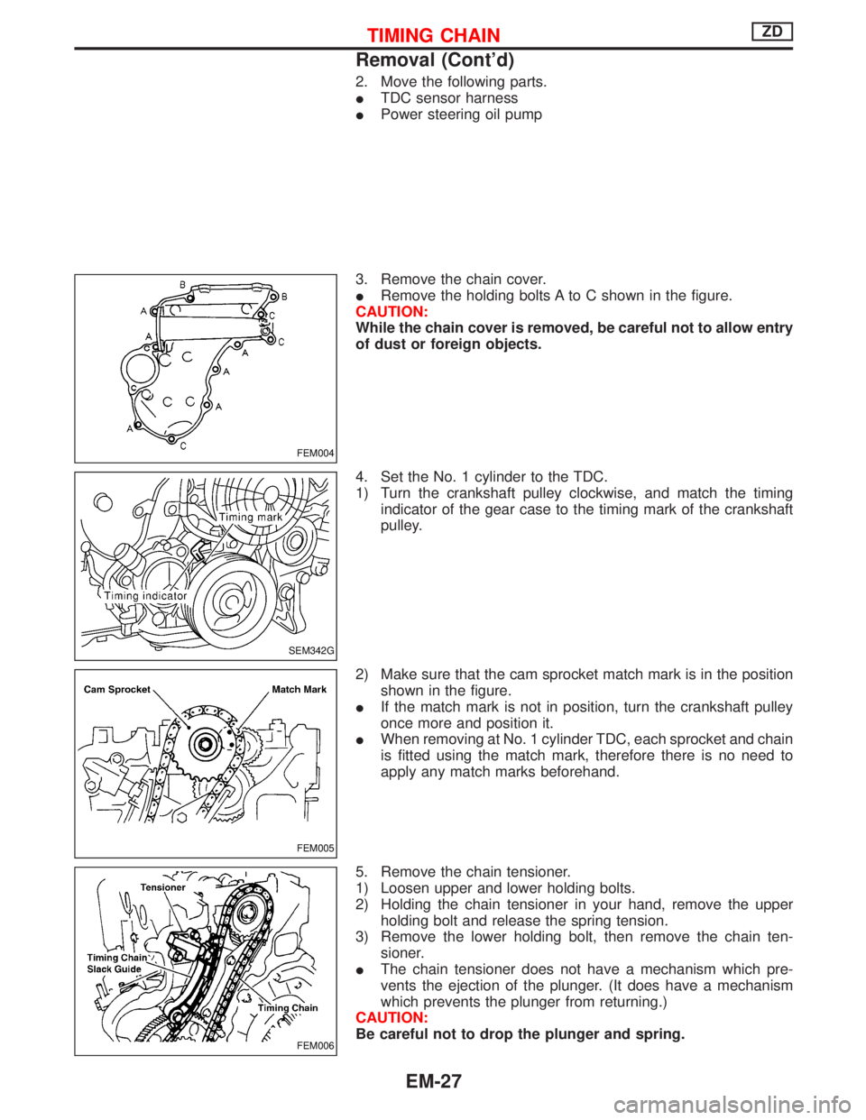
2. Move the following parts.
ITDC sensor harness
IPower steering oil pump
3. Remove the chain cover.
IRemove the holding bolts A to C shown in the figure.
CAUTION:
While the chain cover is removed, be careful not to allow entry
of dust or foreign objects.
4. Set the No. 1 cylinder to the TDC.
1) Turn the crankshaft pulley clockwise, and match the timing
indicator of the gear case to the timing mark of the crankshaft
pulley.
2) Make sure that the cam sprocket match mark is in the position
shown in the figure.
IIf the match mark is not in position, turn the crankshaft pulley
once more and position it.
IWhen removing at No. 1 cylinder TDC, each sprocket and chain
is fitted using the match mark, therefore there is no need to
apply any match marks beforehand.
5. Remove the chain tensioner.
1) Loosen upper and lower holding bolts.
2) Holding the chain tensioner in your hand, remove the upper
holding bolt and release the spring tension.
3) Remove the lower holding bolt, then remove the chain ten-
sioner.
IThe chain tensioner does not have a mechanism which pre-
vents the ejection of the plunger. (It does have a mechanism
which prevents the plunger from returning.)
CAUTION:
Be careful not to drop the plunger and spring.
FEM004
SEM342G
FEM005
FEM006
TIMING CHAINZD
Removal (Cont'd)
EM-27
Page 1137 of 1767
3) Install the chain cover.
IThe dimension below the neck of the holding bolt will vary
depending on the part.
Dimension below the neck:
A: 20 mm (0.79 in)
B: 50 mm (1.97 in)
C: 60 mm (2.36 in)
6. Install by following all removal procedures in reverse.
CAUTION:
IArrange the TDC sensor harness in the position shown in
the figure.
IMake sure that the harness has no deflection around the
vicinity of the crankshaft pulley when installing the clamp.
FEM004
SEM349G
TIMING CHAINZD
Installation (Cont'd)
EM-29
Page 1143 of 1767
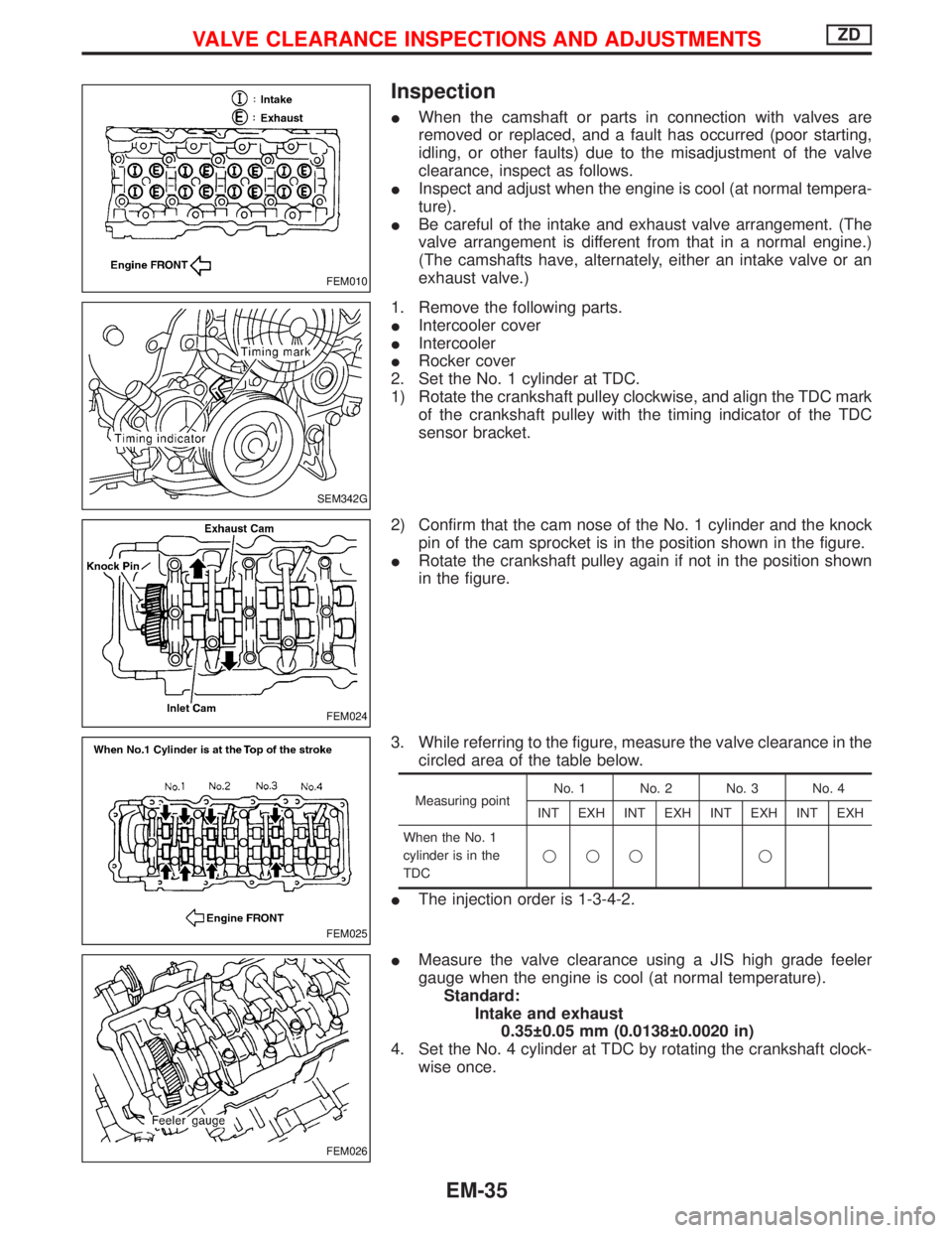
Inspection
IWhen the camshaft or parts in connection with valves are
removed or replaced, and a fault has occurred (poor starting,
idling, or other faults) due to the misadjustment of the valve
clearance, inspect as follows.
IInspect and adjust when the engine is cool (at normal tempera-
ture).
IBe careful of the intake and exhaust valve arrangement. (The
valve arrangement is different from that in a normal engine.)
(The camshafts have, alternately, either an intake valve or an
exhaust valve.)
1. Remove the following parts.
IIntercooler cover
IIntercooler
IRocker cover
2. Set the No. 1 cylinder at TDC.
1) Rotate the crankshaft pulley clockwise, and align the TDC mark
of the crankshaft pulley with the timing indicator of the TDC
sensor bracket.
2) Confirm that the cam nose of the No. 1 cylinder and the knock
pin of the cam sprocket is in the position shown in the figure.
IRotate the crankshaft pulley again if not in the position shown
in the figure.
3. While referring to the figure, measure the valve clearance in the
circled area of the table below.
Measuring pointNo. 1 No. 2 No. 3 No. 4
INT EXH INT EXH INT EXH INT EXH
When the No. 1
cylinder is in the
TDCqqq q
IThe injection order is 1-3-4-2.
IMeasure the valve clearance using a JIS high grade feeler
gauge when the engine is cool (at normal temperature).
Standard:
Intake and exhaust
0.35 0.05 mm (0.0138 0.0020 in)
4. Set the No. 4 cylinder at TDC by rotating the crankshaft clock-
wise once.
FEM010
SEM342G
FEM024
FEM025
FEM026
VALVE CLEARANCE INSPECTIONS AND ADJUSTMENTSZD
EM-35
Page 1147 of 1767
Removal
1. Remove the engine assembly.
Refer to ªENGINE REMOVALº, EM-63.
2. Place the engine on an engine stand (SST).
Refer to ªCYLINDER BLOCKº, EM-67.
3. Remove the following.
IAuto tensioner bracket
IAir conditioner bracket
IAlternator bracket
IOil tube
IVacuum pump
IRocker cover
IOil pan (upper, lower)
IInjection tube
ISpill tube
IHigh pressure nozzle assembly
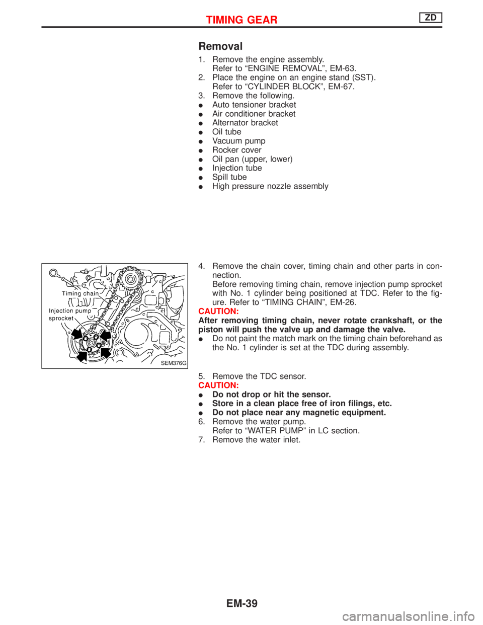
4. Remove the chain cover, timing chain and other parts in con-
nection.
Before removing timing chain, remove injection pump sprocket
with No. 1 cylinder being positioned at TDC. Refer to the fig-
ure. Refer to ªTIMING CHAINº, EM-26.
CAUTION:
After removing timing chain, never rotate crankshaft, or the
piston will push the valve up and damage the valve.
IDo not paint the match mark on the timing chain beforehand as
the No. 1 cylinder is set at the TDC during assembly.
5. Remove the TDC sensor.
CAUTION:
IDo not drop or hit the sensor.
IStore in a clean place free of iron filings, etc.
IDo not place near any magnetic equipment.
6. Remove the water pump.
Refer to ªWATER PUMPº in LC section.
7. Remove the water inlet.
SEM376G
TIMING GEARZD
EM-39
Page 1156 of 1767
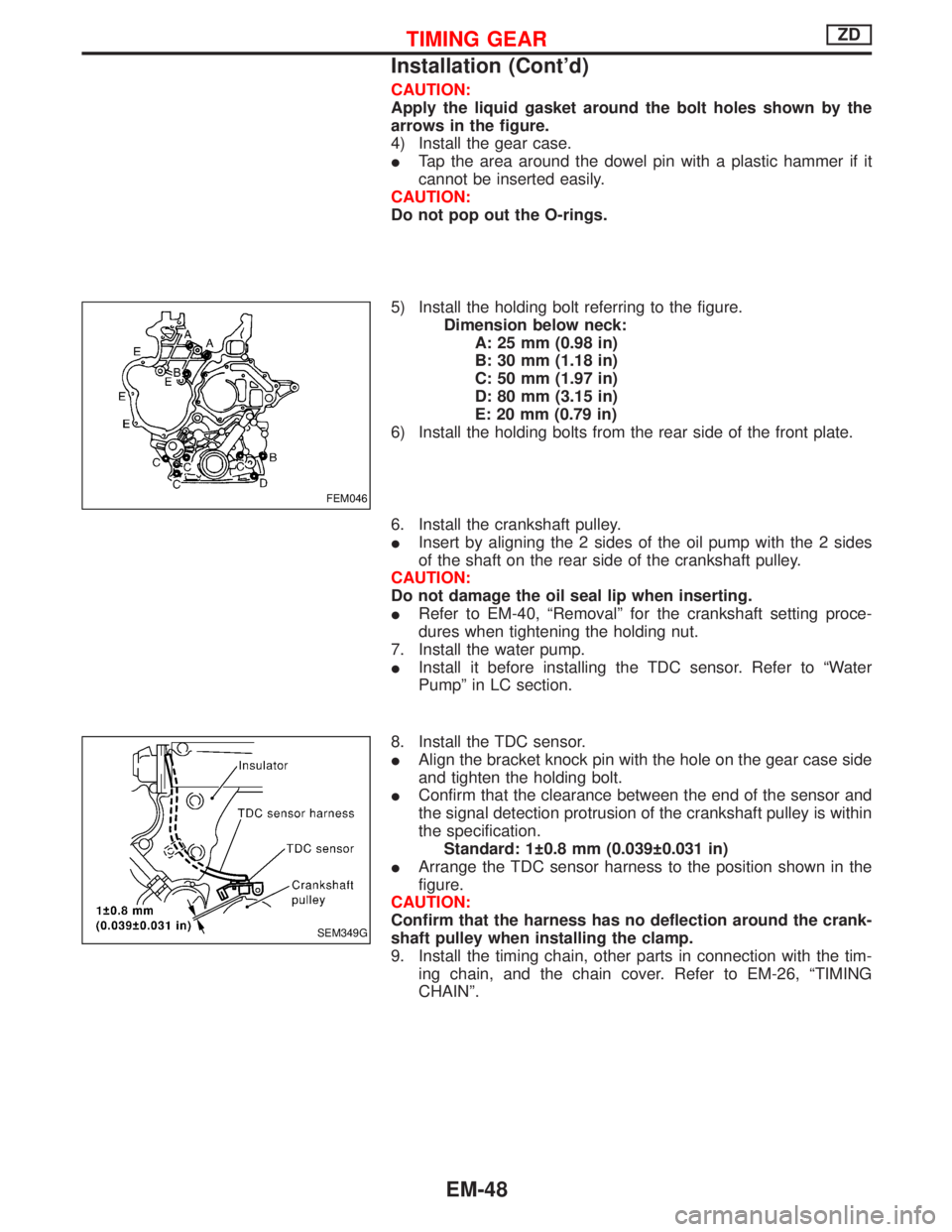
CAUTION:
Apply the liquid gasket around the bolt holes shown by the
arrows in the figure.
4) Install the gear case.
ITap the area around the dowel pin with a plastic hammer if it
cannot be inserted easily.
CAUTION:
Do not pop out the O-rings.
5) Install the holding bolt referring to the figure.
Dimension below neck:
A: 25 mm (0.98 in)
B: 30 mm (1.18 in)
C: 50 mm (1.97 in)
D: 80 mm (3.15 in)
E: 20 mm (0.79 in)
6) Install the holding bolts from the rear side of the front plate.
6. Install the crankshaft pulley.
IInsert by aligning the 2 sides of the oil pump with the 2 sides
of the shaft on the rear side of the crankshaft pulley.
CAUTION:
Do not damage the oil seal lip when inserting.
IRefer to EM-40, ªRemovalº for the crankshaft setting proce-
dures when tightening the holding nut.
7. Install the water pump.
IInstall it before installing the TDC sensor. Refer to ªWater
Pumpº in LC section.
8. Install the TDC sensor.
IAlign the bracket knock pin with the hole on the gear case side
and tighten the holding bolt.
IConfirm that the clearance between the end of the sensor and
the signal detection protrusion of the crankshaft pulley is within
the specification.
Standard: 1 0.8 mm (0.039 0.031 in)
IArrange the TDC sensor harness to the position shown in the
figure.
CAUTION:
Confirm that the harness has no deflection around the crank-
shaft pulley when installing the clamp.
9. Install the timing chain, other parts in connection with the tim-
ing chain, and the chain cover. Refer to EM-26, ªTIMING
CHAINº.
FEM046
SEM349G
TIMING GEARZD
Installation (Cont'd)
EM-48
Page 1208 of 1767
q1Intake manifold
q
2Oil cooler
q
3Injection pump drive gearq
4Dust cover
q
5Engine revolution sensor
q
6Air conditioner compressorq
7Idler pulley
q
8Electronic injection pump
NEM324
ENGINE COMPONENTS Ð Outer PartsTD27Ti
EM-100
Page 1300 of 1767
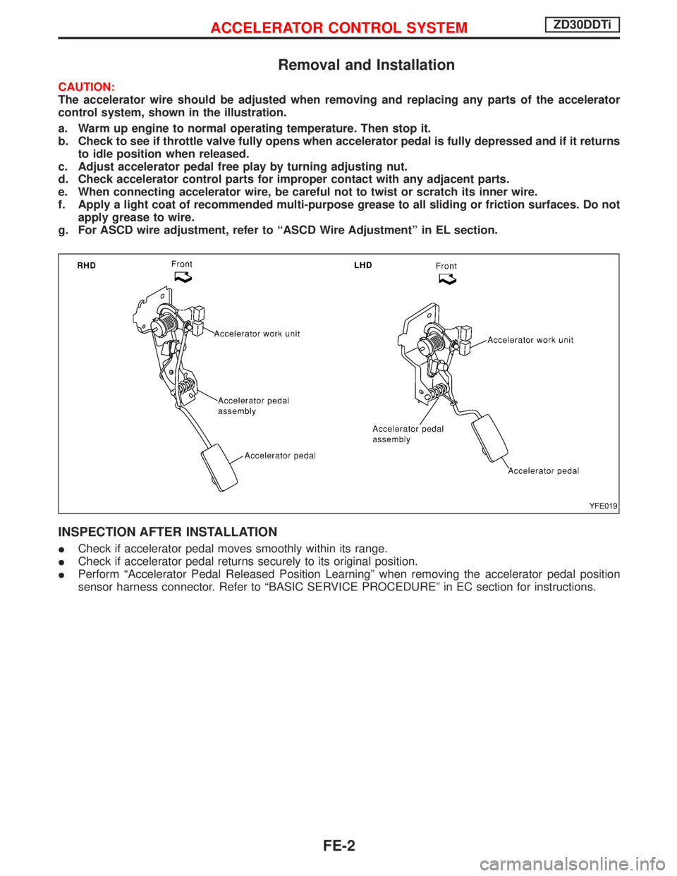
Removal and Installation
CAUTION:
The accelerator wire should be adjusted when removing and replacing any parts of the accelerator
control system, shown in the illustration.
a. Warm up engine to normal operating temperature. Then stop it.
b. Check to see if throttle valve fully opens when accelerator pedal is fully depressed and if it returns
to idle position when released.
c. Adjust accelerator pedal free play by turning adjusting nut.
d. Check accelerator control parts for improper contact with any adjacent parts.
e. When connecting accelerator wire, be careful not to twist or scratch its inner wire.
f. Apply a light coat of recommended multi-purpose grease to all sliding or friction surfaces. Do not
apply grease to wire.
g. For ASCD wire adjustment, refer to ªASCD Wire Adjustmentº in EL section.
INSPECTION AFTER INSTALLATION
ICheck if accelerator pedal moves smoothly within its range.
ICheck if accelerator pedal returns securely to its original position.
IPerform ªAccelerator Pedal Released Position Learningº when removing the accelerator pedal position
sensor harness connector. Refer to ªBASIC SERVICE PROCEDUREº in EC section for instructions.
YFE019
ACCELERATOR CONTROL SYSTEMZD30DDTi
FE-2
Page 1303 of 1767
Adjusting Accelerator Cable
q1Pedal bracket
q
2Accelerator switchq
3Accelerator position sensor
q
4Accelerator cableq
5Return spring
q
6Accelerator pedal
INSPECTION AFTER INSTALLATION
ICheck if accelerator pedal moves smoothly within its range.
ICheck if accelerator pedal returns securely to its original position.
IPerform ªAccelerator Pedal Released Position Learningº when removing the accelerator pedal position
sensor harness connector. Refer to ªBASIC SERVICE PROCEDUREº in EC section for instructions.
IIf MI illuminates after engine has started, refer to ªON BOARD DIAGNOSTIC SYSTEM DESCRIPTIONº
in EC section for instructions.
NFE032
ACCELERATOR CONTROL SYSTEMTD27Ti
FE-5