Page 771 of 1767
Component Description
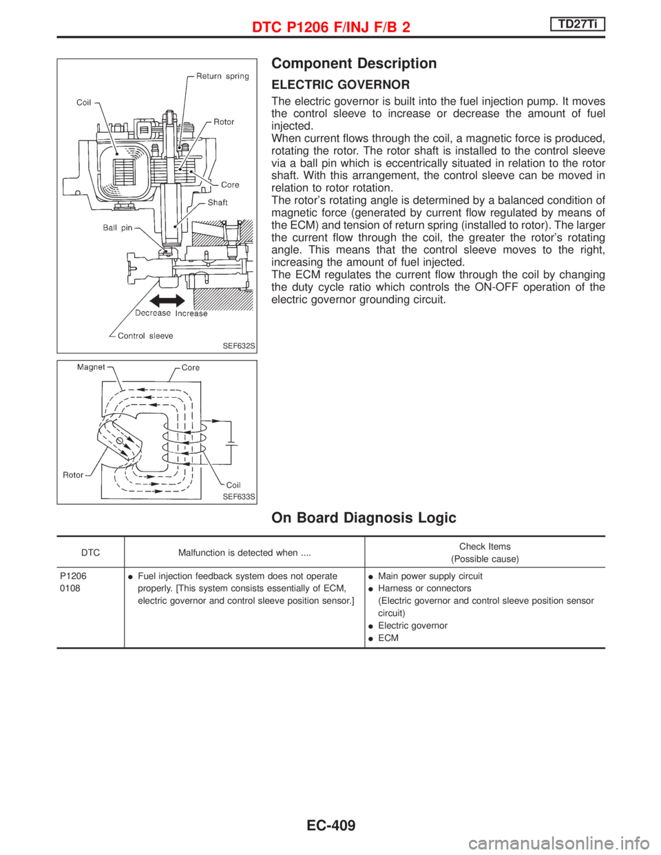
ELECTRIC GOVERNOR
The electric governor is built into the fuel injection pump. It moves
the control sleeve to increase or decrease the amount of fuel
injected.
When current flows through the coil, a magnetic force is produced,
rotating the rotor. The rotor shaft is installed to the control sleeve
via a ball pin which is eccentrically situated in relation to the rotor
shaft. With this arrangement, the control sleeve can be moved in
relation to rotor rotation.
The rotor's rotating angle is determined by a balanced condition of
magnetic force (generated by current flow regulated by means of
the ECM) and tension of return spring (installed to rotor). The larger
the current flow through the coil, the greater the rotor's rotating
angle. This means that the control sleeve moves to the right,
increasing the amount of fuel injected.
The ECM regulates the current flow through the coil by changing
the duty cycle ratio which controls the ON-OFF operation of the
electric governor grounding circuit.
On Board Diagnosis Logic
DTC Malfunction is detected when ....Check Items
(Possible cause)
P1206
0108IFuel injection feedback system does not operate
properly. [This system consists essentially of ECM,
electric governor and control sleeve position sensor.]IMain power supply circuit
IHarness or connectors
(Electric governor and control sleeve position sensor
circuit)
IElectric governor
IECM
SEF632S
SEF633S
DTC P1206 F/INJ F/B 2TD27Ti
EC-409
Page 776 of 1767
Component Description
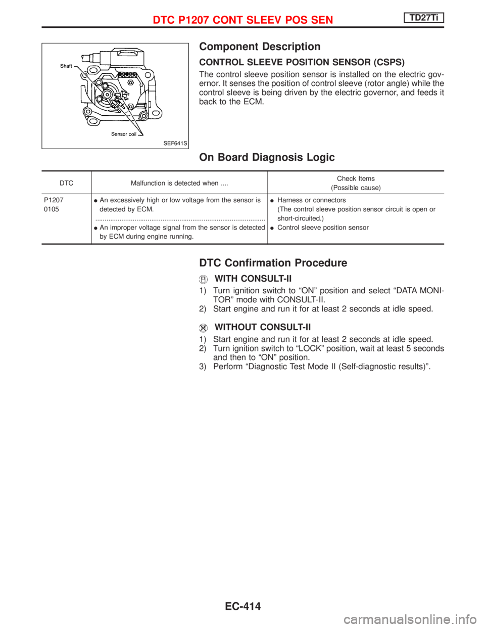
CONTROL SLEEVE POSITION SENSOR (CSPS)
The control sleeve position sensor is installed on the electric gov-
ernor. It senses the position of control sleeve (rotor angle) while the
control sleeve is being driven by the electric governor, and feeds it
back to the ECM.
On Board Diagnosis Logic
DTC Malfunction is detected when ....Check Items
(Possible cause)
P1207
0105IAn excessively high or low voltage from the sensor is
detected by ECM.
...........................................................................................
IAn improper voltage signal from the sensor is detected
by ECM during engine running.IHarness or connectors
(The control sleeve position sensor circuit is open or
short-circuited.)
IControl sleeve position sensor
DTC Confirmation Procedure
WITH CONSULT-II
1) Turn ignition switch to ªONº position and select ªDATA MONI-
TORº mode with CONSULT-II.
2) Start engine and run it for at least 2 seconds at idle speed.
WITHOUT CONSULT-II
1) Start engine and run it for at least 2 seconds at idle speed.
2) Turn ignition switch to ªLOCKº position, wait at least 5 seconds
and then to ªONº position.
3) Perform ªDiagnostic Test Mode II (Self-diagnostic results)º.
SEF641S
DTC P1207 CONT SLEEV POS SENTD27Ti
EC-414
Page 778 of 1767
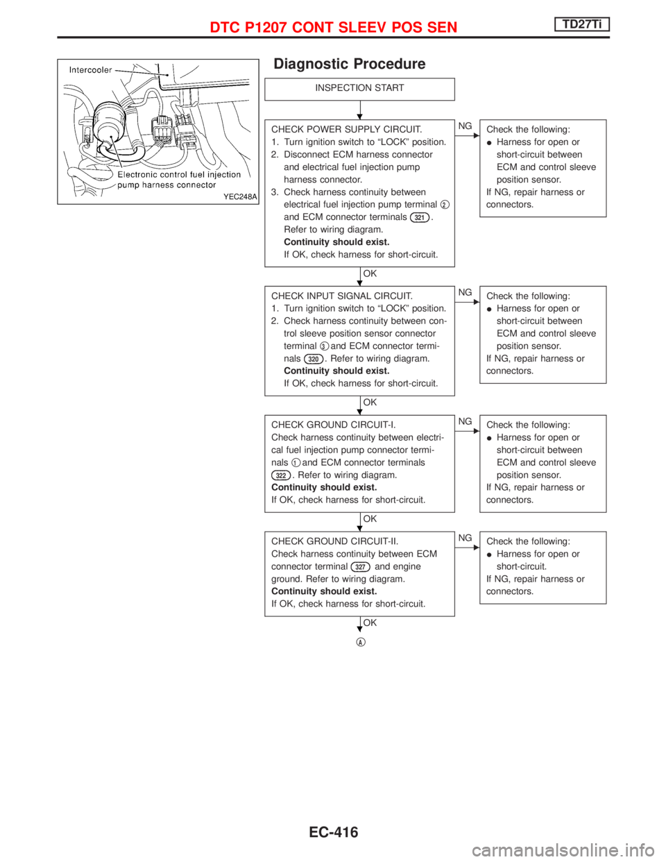
Diagnostic Procedure
INSPECTION START
CHECK POWER SUPPLY CIRCUIT.
1. Turn ignition switch to ªLOCKº position.
2. Disconnect ECM harness connector
and electrical fuel injection pump
harness connector.
3. Check harness continuity between
electrical fuel injection pump terminalq
2
and ECM connector terminals321.
Refer to wiring diagram.
Continuity should exist.
If OK, check harness for short-circuit.
OK
ENG
Check the following:
IHarness for open or
short-circuit between
ECM and control sleeve
position sensor.
If NG, repair harness or
connectors.
CHECK INPUT SIGNAL CIRCUIT.
1. Turn ignition switch to ªLOCKº position.
2. Check harness continuity between con-
trol sleeve position sensor connector
terminalq
3and ECM connector termi-
nals
320. Refer to wiring diagram.
Continuity should exist.
If OK, check harness for short-circuit.
OK
ENG
Check the following:
IHarness for open or
short-circuit between
ECM and control sleeve
position sensor.
If NG, repair harness or
connectors.
CHECK GROUND CIRCUIT-I.
Check harness continuity between electri-
cal fuel injection pump connector termi-
nalsq
1and ECM connector terminals
322. Refer to wiring diagram.
Continuity should exist.
If OK, check harness for short-circuit.
OK
ENG
Check the following:
IHarness for open or
short-circuit between
ECM and control sleeve
position sensor.
If NG, repair harness or
connectors.
CHECK GROUND CIRCUIT-II.
Check harness continuity between ECM
connector terminal
327and engine
ground. Refer to wiring diagram.
Continuity should exist.
If OK, check harness for short-circuit.
OK
ENG
Check the following:
IHarness for open or
short-circuit.
If NG, repair harness or
connectors.
qA
YEC248A
H
H
H
H
H
DTC P1207 CONT SLEEV POS SENTD27Ti
EC-416
Page 779 of 1767
qA
CHECK COMPONENT
(Control sleeve position sensor).
Refer to ªCOMPONENT INSPECTIONº on
page EC-417.
OK
ENG
Have the injection pump
assembly serviced by an
authorised service repre-
sentative.
Disconnect and reconnect harness con-
nectors in the circuit. Then retest.
Trouble is not fixed.
Check ECM pin terminals for damage and
check the connection of ECM harness
connector. Reconnect ECM harness con-
nector and retest.
INSPECTION END
Component Inspection
CONTROL SLEEVE POSITION SENSOR
1. Disconnect control sleeve position sensor & electric governor
harness connector.
2. Check continuity between terminalsq
1andq3,q2andq3.
Resistance: Approximately 6.1W[at 25ÉC (77ÉF)]
If NG, take proper action.
YEC259A
H
H
H
H
DTC P1207 CONT SLEEV POS SENTD27Ti
Diagnostic Procedure (Cont'd)
EC-417
Page 780 of 1767
Description
SYSTEM DESCRIPTION
Sensor Input signal to ECM ECM function Actuator
Engine coolant temperature
sensorEngine coolant temperature
Cooling fan control Cooling fan relay
Air conditioner switch Air conditioner ªONº signal
The ECM controls the cooling fan corresponding to the vehicle speed, engine coolant temperature, air condi-
tioner ON signal.
On Board Diagnosis Logic
This diagnosis continuously monitors the engine coolant temperature.
If the cooling fan or another component in the cooling system malfunctions, engine coolant temperature will
rise.
When the engine coolant temperature reaches an abnormally high temperature condition, a malfunction is
indicated.
DTC Malfunction is detected when ... Check Items (Possible Cause)
P1217
0208ICooling fan does not operate properly (Overheat).
ICooling fan system does not operate properly (Over-
heat).
IEngine coolant was not added to the system using
the proper filling method.IHarness or connectors
(The cooling fan circuit is open or shorted.)
ICooling fan
IRadiator hose
IRadiator
IRadiator cap
IWater pump
IThermostat
IEngine coolant temperature sensor
For more information, refer to ªMAIN 12 CAUSES OF
OVERHEATINGº, EC-425.
CAUTION:
When a malfunction is indicated, be sure to replace the coolant following the procedure in the LC
section, ªChanging Engine Coolantº. Also, replace the engine oil.
1) Fill radiator with coolant up to specified level with a filling speed of 2 liters per minute. Be sure to
use coolant with the proper mixture ratio. Refer to MA section, ªEngine Coolant Mixture Ratioº.
2) After refilling coolant, run engine to ensure that no water-flow noise is emitted.
DTC P1217 OVER HEATTD27Ti
EC-418
Page 781 of 1767
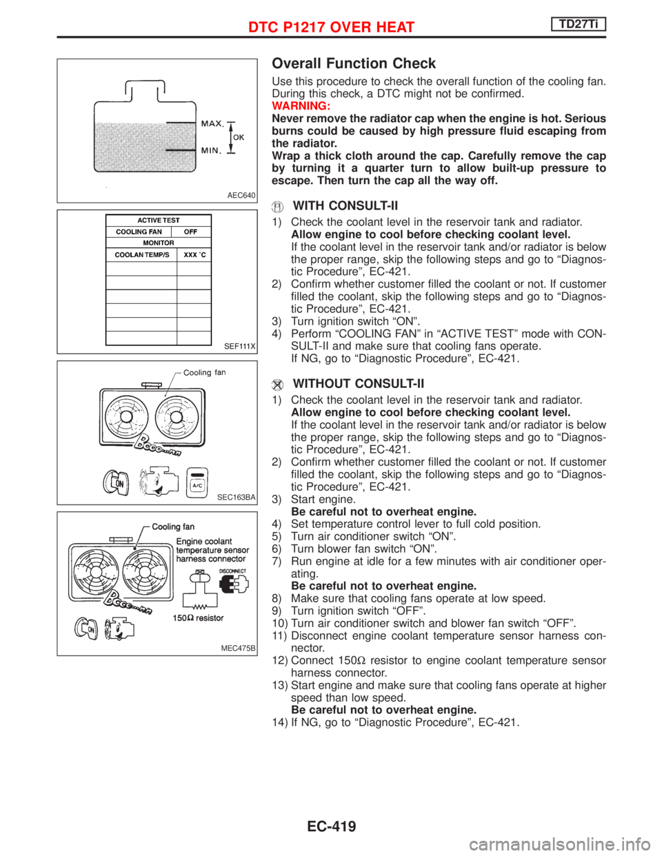
Overall Function Check
Use this procedure to check the overall function of the cooling fan.
During this check, a DTC might not be confirmed.
WARNING:
Never remove the radiator cap when the engine is hot. Serious
burns could be caused by high pressure fluid escaping from
the radiator.
Wrap a thick cloth around the cap. Carefully remove the cap
by turning it a quarter turn to allow built-up pressure to
escape. Then turn the cap all the way off.
WITH CONSULT-II
1) Check the coolant level in the reservoir tank and radiator.
Allow engine to cool before checking coolant level.
If the coolant level in the reservoir tank and/or radiator is below
the proper range, skip the following steps and go to ªDiagnos-
tic Procedureº, EC-421.
2) Confirm whether customer filled the coolant or not. If customer
filled the coolant, skip the following steps and go to ªDiagnos-
tic Procedureº, EC-421.
3) Turn ignition switch ªONº.
4) Perform ªCOOLING FANº in ªACTIVE TESTº mode with CON-
SULT-II and make sure that cooling fans operate.
If NG, go to ªDiagnostic Procedureº, EC-421.
WITHOUT CONSULT-II
1) Check the coolant level in the reservoir tank and radiator.
Allow engine to cool before checking coolant level.
If the coolant level in the reservoir tank and/or radiator is below
the proper range, skip the following steps and go to ªDiagnos-
tic Procedureº, EC-421.
2) Confirm whether customer filled the coolant or not. If customer
filled the coolant, skip the following steps and go to ªDiagnos-
tic Procedureº, EC-421.
3) Start engine.
Be careful not to overheat engine.
4) Set temperature control lever to full cold position.
5) Turn air conditioner switch ªONº.
6) Turn blower fan switch ªONº.
7) Run engine at idle for a few minutes with air conditioner oper-
ating.
Be careful not to overheat engine.
8) Make sure that cooling fans operate at low speed.
9) Turn ignition switch ªOFFº.
10) Turn air conditioner switch and blower fan switch ªOFFº.
11) Disconnect engine coolant temperature sensor harness con-
nector.
12) Connect 150Wresistor to engine coolant temperature sensor
harness connector.
13) Start engine and make sure that cooling fans operate at higher
speed than low speed.
Be careful not to overheat engine.
14) If NG, go to ªDiagnostic Procedureº, EC-421.
AEC640
SEF111X
SEC163BA
MEC475B
DTC P1217 OVER HEATTD27Ti
EC-419
Page 786 of 1767
qc
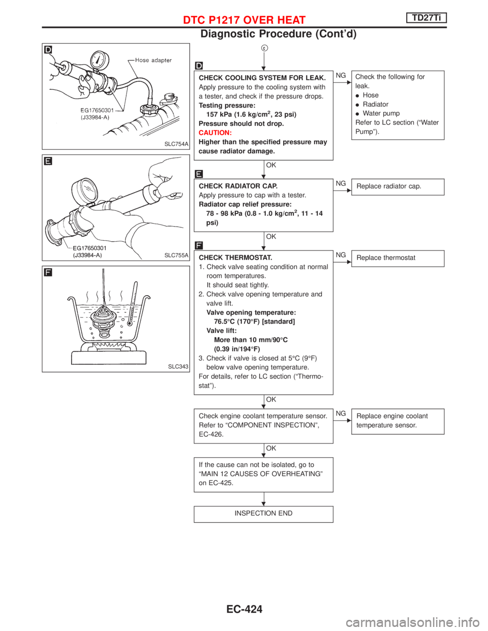
CHECK COOLING SYSTEM FOR LEAK.
Apply pressure to the cooling system with
a tester, and check if the pressure drops.
Testing pressure:
157 kPa (1.6 kg/cm
2, 23 psi)
Pressure should not drop.
CAUTION:
Higher than the specified pressure may
cause radiator damage.
OK
ENG
Check the following for
leak.
IHose
IRadiator
IWater pump
Refer to LC section (ªWater
Pumpº).
CHECK RADIATOR CAP.
Apply pressure to cap with a tester.
Radiator cap relief pressure:
78 - 98 kPa (0.8 - 1.0 kg/cm
2,11-14
psi)
OK
ENG
Replace radiator cap.
CHECK THERMOSTAT.
1. Check valve seating condition at normal
room temperatures.
It should seat tightly.
2. Check valve opening temperature and
valve lift.
Valve opening temperature:
76.5ÉC (170ÉF) [standard]
Valve lift:
More than 10 mm/90ÉC
(0.39 in/194ÉF)
3. Check if valve is closed at 5ÉC (9ÉF)
below valve opening temperature.
For details, refer to LC section (ªThermo-
statº).
OK
ENG
Replace thermostat
Check engine coolant temperature sensor.
Refer to ªCOMPONENT INSPECTIONº,
EC-426.
OK
ENG
Replace engine coolant
temperature sensor.
If the cause can not be isolated, go to
ªMAIN 12 CAUSES OF OVERHEATINGº
on EC-425.
INSPECTION END
SLC754A
SLC755A
SLC343
H
H
H
H
H
H
DTC P1217 OVER HEATTD27Ti
Diagnostic Procedure (Cont'd)
EC-424
Page 789 of 1767
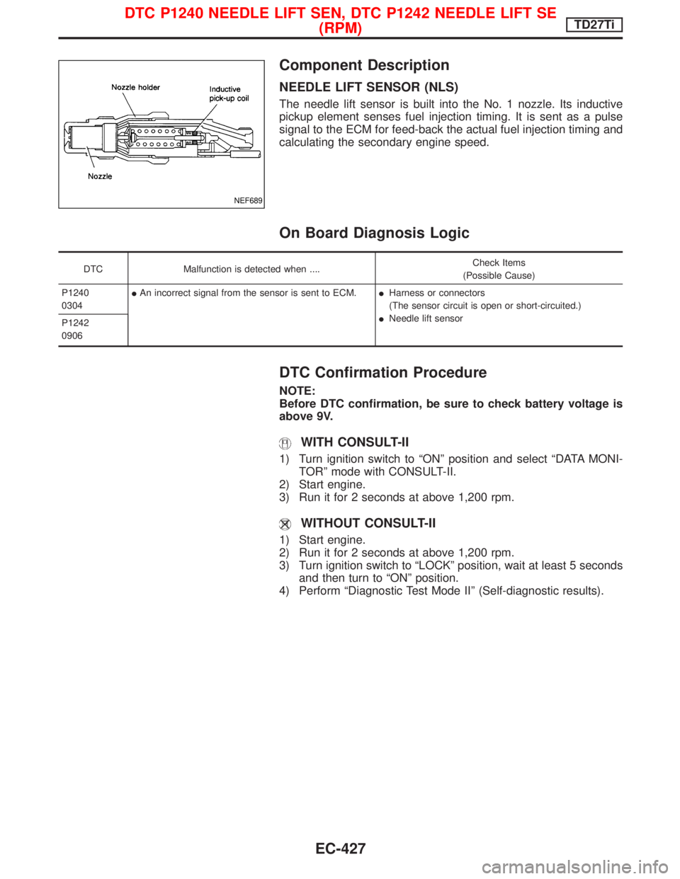
Component Description
NEEDLE LIFT SENSOR (NLS)
The needle lift sensor is built into the No. 1 nozzle. Its inductive
pickup element senses fuel injection timing. It is sent as a pulse
signal to the ECM for feed-back the actual fuel injection timing and
calculating the secondary engine speed.
On Board Diagnosis Logic
DTC Malfunction is detected when ....Check Items
(Possible Cause)
P1240
0304IAn incorrect signal from the sensor is sent to ECM.IHarness or connectors
(The sensor circuit is open or short-circuited.)
INeedle lift sensor
P1242
0906
DTC Confirmation Procedure
NOTE:
Before DTC confirmation, be sure to check battery voltage is
above 9V.
WITH CONSULT-II
1) Turn ignition switch to ªONº position and select ªDATA MONI-
TORº mode with CONSULT-II.
2) Start engine.
3) Run it for 2 seconds at above 1,200 rpm.
WITHOUT CONSULT-II
1) Start engine.
2) Run it for 2 seconds at above 1,200 rpm.
3) Turn ignition switch to ªLOCKº position, wait at least 5 seconds
and then turn to ªONº position.
4) Perform ªDiagnostic Test Mode IIº (Self-diagnostic results).
NEF689
DTC P1240 NEEDLE LIFT SEN, DTC P1242 NEEDLE LIFT SE
(RPM)TD27Ti
EC-427