2002 NISSAN TERRANO sensor
[x] Cancel search: sensorPage 699 of 1767

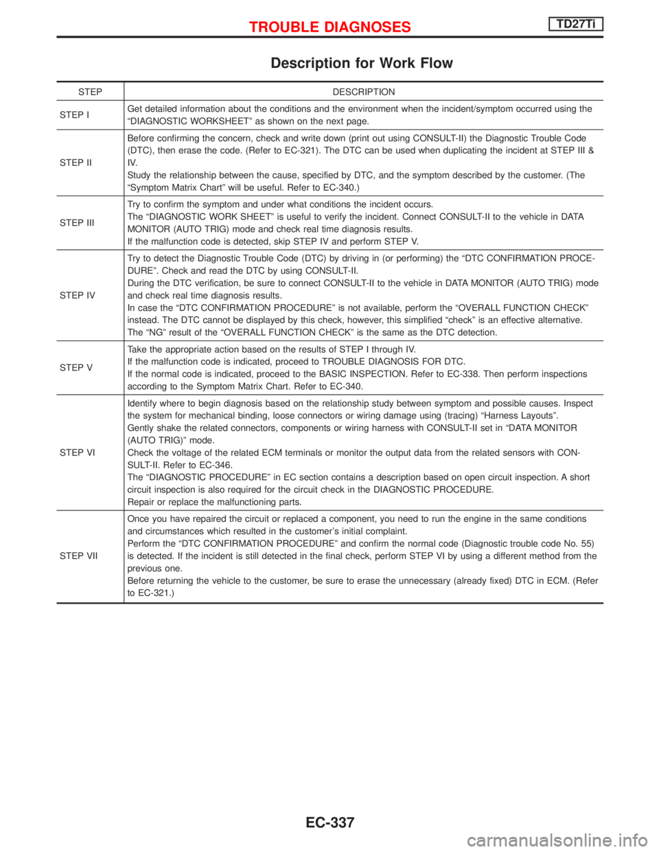
Description for Work Flow
STEP DESCRIPTION
STEP IGet detailed information about the conditions and the environment when the incident/symptom occurred using the
ªDIAGNOSTIC WORKSHEETº as shown on the next page.
STEP IIBefore confirming the concern, check and write down (print out using CONSULT-II) the Diagnostic Trouble Code
(DTC), then erase the code. (Refer to EC-321). The DTC can be used when duplicating the incident at STEP III &
IV.
Study the relationship between the cause, specified by DTC, and the symptom described by the customer. (The
ªSymptom Matrix Chartº will be useful. Refer to EC-340.)
STEP IIITry to confirm the symptom and under what conditions the incident occurs.
The ªDIAGNOSTIC WORK SHEETº is useful to verify the incident. Connect CONSULT-II to the vehicle in DATA
MONITOR (AUTO TRIG) mode and check real time diagnosis results.
If the malfunction code is detected, skip STEP IV and perform STEP V.
STEP IVTry to detect the Diagnostic Trouble Code (DTC) by driving in (or performing) the ªDTC CONFIRMATION PROCE-
DUREº. Check and read the DTC by using CONSULT-II.
During the DTC verification, be sure to connect CONSULT-II to the vehicle in DATA MONITOR (AUTO TRIG) mode
and check real time diagnosis results.
In case the ªDTC CONFIRMATION PROCEDUREº is not available, perform the ªOVERALL FUNCTION CHECKº
instead. The DTC cannot be displayed by this check, however, this simplified ªcheckº is an effective alternative.
The ªNGº result of the ªOVERALL FUNCTION CHECKº is the same as the DTC detection.
STEP VTake the appropriate action based on the results of STEP I through IV.
If the malfunction code is indicated, proceed to TROUBLE DIAGNOSIS FOR DTC.
If the normal code is indicated, proceed to the BASIC INSPECTION. Refer to EC-338. Then perform inspections
according to the Symptom Matrix Chart. Refer to EC-340.
STEP VIIdentify where to begin diagnosis based on the relationship study between symptom and possible causes. Inspect
the system for mechanical binding, loose connectors or wiring damage using (tracing) ªHarness Layoutsº.
Gently shake the related connectors, components or wiring harness with CONSULT-II set in ªDATA MONITOR
(AUTO TRIG)º mode.
Check the voltage of the related ECM terminals or monitor the output data from the related sensors with CON-
SULT-II. Refer to EC-346.
The ªDIAGNOSTIC PROCEDUREº in EC section contains a description based on open circuit inspection. A short
circuit inspection is also required for the circuit check in the DIAGNOSTIC PROCEDURE.
Repair or replace the malfunctioning parts.
STEP VIIOnce you have repaired the circuit or replaced a component, you need to run the engine in the same conditions
and circumstances which resulted in the customer's initial complaint.
Perform the ªDTC CONFIRMATION PROCEDUREº and confirm the normal code (Diagnostic trouble code No. 55)
is detected. If the incident is still detected in the final check, perform STEP VI by using a different method from the
previous one.
Before returning the vehicle to the customer, be sure to erase the unnecessary (already fixed) DTC in ECM. (Refer
to EC-321.)
TROUBLE DIAGNOSESTD27Ti
EC-337
Page 703 of 1767

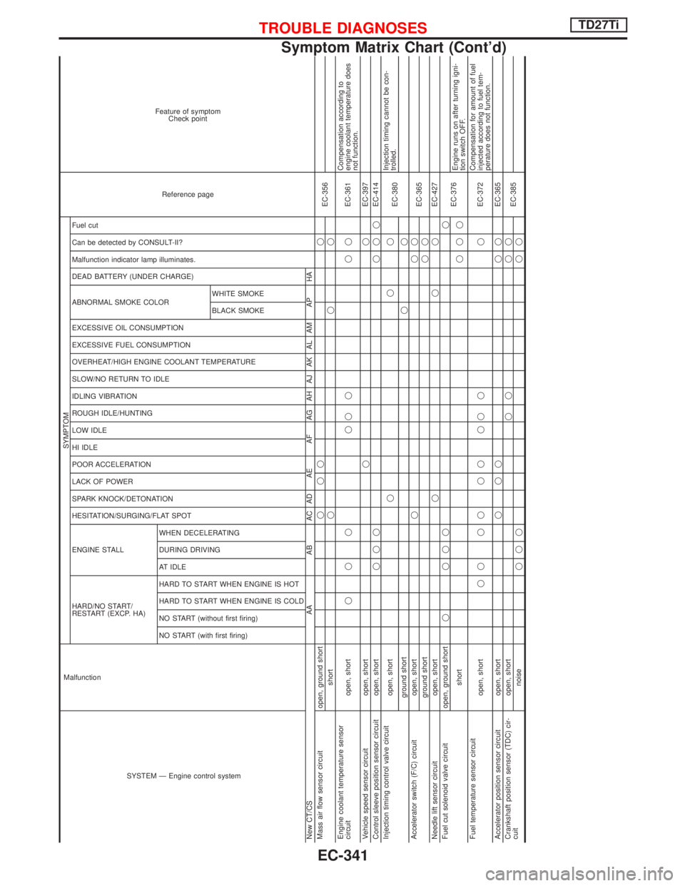
SYSTEM Ð Engine control system Malfunction
SYMPTOM
Reference page Feature of symptom
Check point
HARD/NO START/
RESTART (EXCP. HA) ENGINE STALL HESITATION/SURGING/FLAT SPOT SPARK KNOCK/DETONATION
LACK OF POWER
POOR ACCELERATION
HI IDLE
LOW IDLE
ROUGH IDLE/HUNTING
IDLING VIBRATION
SLOW/NO RETURN TO IDLE
OVERHEAT/HIGH ENGINE COOLANT TEMPERATURE
EXCESSIVE FUEL CONSUMPTION
EXCESSIVE OIL CONSUMPTION ABNORMAL SMOKE COLOR
DEAD BATTERY (UNDER CHARGE) Malfunction indicator lamp illuminates.
Can be detected by CONSULT-II?
Fuel cut
NO START (with first firing) NO START (without first firing)
HARD TO START WHEN ENGINE IS COLD
HARD TO START WHEN ENGINE IS HOT
AT IDLE
DURING DRIVING
WHEN DECELERATINGBLACK SMOKE WHITE SMOKE
New CT/CS AA AB AC AD AE AF AG AH AJ AK AL AM AP HA
Mass air flow sensor circuit open, ground shortqqq q
EC-356
shortqqq
Engine coolant temperature sensor
circuit open, shortqqq qqq qqEC-361Compensation according to
engine coolant temperature does
not function.
Vehicle speed sensor circuit open, shortqqEC-397
Control sleeve position sensor circuit open, shortqqqqqqEC-414
Injection timing control valve circuit
open, shortqqq
EC-380Injection timing cannot be con-
trolled.
ground shortqq
Accelerator switch (F/C) circuit open, shortqqq
EC-365
ground shortqq
Needle lift sensor circuit open, shortqqqEC-427
Fuel cut solenoid valve circuit open, ground shortq qqqq
EC-376
shortqqqEngine runs on after turning igni-
tion switch OFF.
Fuel temperature sensor circuit
open, shortqq qq qq qq q qEC-372Compensation for amount of fuel
injected according to fuel tem-
perature does not function.
Accelerator position sensor circuit open, shortqqq qqEC-365
Crankshaft position sensor (TDC) cir-
cuitopen, shortqq qq
EC-385
noiseqqqqq
TROUBLE DIAGNOSESTD27Ti
Symptom Matrix Chart (Cont'd)
EC-341
Page 707 of 1767

Major Sensor Reference Graph in Data Monitor
Mode
The following are the major sensor reference graphs in ªDATA MONITORº mode.
(Select ªHI SPEEDº in ªDATA MONITORº with CONSULT-II.)
ACCEL POS SEN, C/SLEEV POS/S, ACT INJ TIMG
Below is the data for ªACCEL POS SENº, ªC/SLEEV POS/Sº and ªACT INJ TIMGº when revving engine quickly
up to 3,000 rpm under no load after warming up engine sufficiently.
Each value is for reference, the exact value may vary.
NEF766
TROUBLE DIAGNOSESTD27Ti
EC-345
Page 708 of 1767

ECM Terminals and Reference Value
PREPARATION
Perform all voltage measurements with all the connectors con-
nected. Measure ECM terminal voltage at the nearest connector to
the sensors or actuators to be measured as accessing ECM termi-
nals from outside is impossible.
IUse extreme care not to touch 2 pins at the same time.
IData is for comparison and may not be exact.
IUse care not to enlarge the opening to keep the seal in good
condition.
Be sure ECM unit is properly grounded before checking.
ECM HARNESS CONNECTOR TERMINAL LAYOUT
SGI841
MEC032E
TROUBLE DIAGNOSESTD27Ti
EC-346
Page 710 of 1767
![NISSAN TERRANO 2002 Service Repair Manual TERMI-
NAL
NO.WIRE
COLORITEM CONDITIONDATA (DC Voltage and
Pulse Signal)
210 Y/B EGRC-solenoid valve B[Engine is running]
IWarm-up condition
IIdle speedApproximately 0.4V
[Engine is running]
IWarm-up NISSAN TERRANO 2002 Service Repair Manual TERMI-
NAL
NO.WIRE
COLORITEM CONDITIONDATA (DC Voltage and
Pulse Signal)
210 Y/B EGRC-solenoid valve B[Engine is running]
IWarm-up condition
IIdle speedApproximately 0.4V
[Engine is running]
IWarm-up](/manual-img/5/57393/w960_57393-709.png)
TERMI-
NAL
NO.WIRE
COLORITEM CONDITIONDATA (DC Voltage and
Pulse Signal)
210 Y/B EGRC-solenoid valve B[Engine is running]
IWarm-up condition
IIdle speedApproximately 0.4V
[Engine is running]
IWarm-up condition
IEngine speed is 2,500 rpmBATTERY VOLTAGE
(11 - 14V)
213 G/YThrottle control solenoid
valve[Engine is running]
IWarm-up condition
ILow loadApproximately 0V
Except above condition Battery voltage (12 - 14V)
214 LG Glow relay Refer to ªGlow Control Systemº, EC-389.
215 L Malfunction indicator (MI)[Ignition switch ªONº]Approximately 1.0V
[Engine is running]
IIdle speedBATTERY VOLTAGE
(11 - 14V)
218 G/R Sensors' ground[Engine is running]
IWarm-up condition
IIdle speedApproximately 0V
219 LG/R Cooling fan relay[Engine is running]
ICooling fan is not operatingBATTERY VOLTAGE
(11 - 14V)
[Engine is running]
ICooling fan is operatingApproximately 0.1V
221 G/W Glow lamp[Ignition switch ªONº]
IGlow lamp is ªONºApproximately 1V
[Ignition switch ªONº]
IGlow lamp is ªOFFºBATTERY VOLTAGE
(11 - 14V)
223 R/LMass air flow sensor
power supply[Ignition switch ªONº]Approximately 5V
224 L/W Mass air flow sensor[Engine is running]
IWarm-up condition
IIdle speed1.5 - 2.0V
320 WControl sleeve position
sensor[Engine is running]
IIdle speedApproximately 2.6V
NEF477
321 RControl sleeve position
sensor power supply[Engine is running]
IIdle speedApproximately 2.6V
NEF476
TROUBLE DIAGNOSESTD27Ti
ECM Terminals and Reference Value (Cont'd)
EC-348
Page 711 of 1767
![NISSAN TERRANO 2002 Service Repair Manual TERMI-
NAL
NO.WIRE
COLORITEM CONDITIONDATA (DC Voltage and
Pulse Signal)
322 BControl sleeve position
sensor ground[Engine is running]
IIdle speedApproximately 2.6V
NEF476
325 L ECM relay (Self-shutof NISSAN TERRANO 2002 Service Repair Manual TERMI-
NAL
NO.WIRE
COLORITEM CONDITIONDATA (DC Voltage and
Pulse Signal)
322 BControl sleeve position
sensor ground[Engine is running]
IIdle speedApproximately 2.6V
NEF476
325 L ECM relay (Self-shutof](/manual-img/5/57393/w960_57393-710.png)
TERMI-
NAL
NO.WIRE
COLORITEM CONDITIONDATA (DC Voltage and
Pulse Signal)
322 BControl sleeve position
sensor ground[Engine is running]
IIdle speedApproximately 2.6V
NEF476
325 L ECM relay (Self-shutoff)[Ignition switch ªONº]
[Ignition switch ªOFFº]
IFor a few seconds after turning ignition switch
ªOFFºApproximately 1.4V
[Ignition switch ªOFFº]
IA few seconds passed after turning ignition switch
ªOFFºBATTERY VOLTAGE
(11 - 14V)
331 L/RCrankshaft position sensor
(TDC) ground[Engine is running]
IWarm-up condition
IIdle speedApproximately 0V
333 R Needle lift sensor ground[Ignition switch ªONº]Approximately 0V
334 G/REngine coolant tempera-
ture sensor ground[Ignition switch ªONº]Approximately 0V
335 G/RFuel temperature sensor
ground[Engine is running]Approximately 0V
344 L/GCrankshaft position sensor
(TDC)[Engine is running]
IWarm-up condition
IIdle speedApproximately 0V
SEF333Y
[Engine is running]
IWarm-up condition
IEngine speed is 2,000 rpmApproximately 0V
SEF334Y
345 G Needle lift sensor[Engine is running]
IWarm-up condition
IIdle speedApproximately 3.5V
[Engine is running]
IWarm-up condition
IEngine speed is 2,000 rpmApproximately 3.5V
TROUBLE DIAGNOSESTD27Ti
ECM Terminals and Reference Value (Cont'd)
EC-349
Page 712 of 1767
![NISSAN TERRANO 2002 Service Repair Manual TERMI-
NAL
NO.WIRE
COLORITEM CONDITIONDATA (DC Voltage and
Pulse Signal)
347 LG/WEngine coolant tempera-
ture sensor[Engine is running]Approximately 0 - 4.8V
Output voltage varies with
engine coolant NISSAN TERRANO 2002 Service Repair Manual TERMI-
NAL
NO.WIRE
COLORITEM CONDITIONDATA (DC Voltage and
Pulse Signal)
347 LG/WEngine coolant tempera-
ture sensor[Engine is running]Approximately 0 - 4.8V
Output voltage varies with
engine coolant](/manual-img/5/57393/w960_57393-711.png)
TERMI-
NAL
NO.WIRE
COLORITEM CONDITIONDATA (DC Voltage and
Pulse Signal)
347 LG/WEngine coolant tempera-
ture sensor[Engine is running]Approximately 0 - 4.8V
Output voltage varies with
engine coolant tempera-
ture
348 Y/B Fuel temperature sensor[Engine is running]0.6-5V
Output voltage varies with
fuel temperature.
349 G/RInjection timing control
valve ground[Ignition switch ªONº]Approximately 0V
403 G/R Air conditioner switch[Engine is running]
IAir conditioner switch is ªOFFºBATTERY VOLTAGE
(11 - 14V)
[Engine is running]
IBoth air conditioner switch and blower fan switch
are ªONº
(Compressor is operating)Approximately 0.1V
405 G/Y Stop lamp switch[Ignition switch ªONº]
IBrake pedal fully releasedApproximately 0V
[Ignition switch ªONº]
IBrake pedal depressedBATTERY VOLTAGE
(11 - 14V)
416 Y/RBrake pedal position
switch[Ignition switch ªONº]
IBrake pedal fully releasedBATTERY VOLTAGE
(11 - 14V)
[Ignition switch ªONº]
IBrake pedal depressedApproximately 0V
415 OR
Data link connector for
CONSULT-II[Engine is running]
IIdle speed (CONSULT-II is connected and turned
on)Approximately 0V
420 OR/RBATTERY VOLTAGE
(11 - 14V)
417 Y/B Vehicle speed sensor[Engine is running]
ILift up the vehicle
IIn 1st gear position
IVehicle speed is 10 km/h (6 MPH)0 - Approximately 8V
SEF891Y
[Engine is running]
ILift up the vehicle
IIn 2nd gear position
IVehicle speed is 30 km/h (19 MPH)Approximately 6V
SEF892Y
422 PU Start signal[Ignition switch ªONº]Approximately 0V
[Ignition switch ªSTARTº]BATTERY VOLTAGE
(11 - 14V)
425 R/BAccelerator position sen-
sor ground[Engine is running]
IWarm-up condition
IIdle speedApproximately 0V
TROUBLE DIAGNOSESTD27Ti
ECM Terminals and Reference Value (Cont'd)
EC-350
Page 718 of 1767

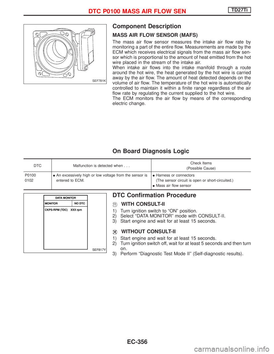
Component Description
MASS AIR FLOW SENSOR (MAFS)
The mass air flow sensor measures the intake air flow rate by
monitoring a part of the entire flow. Measurements are made by the
ECM which receives electrical signals from the mass air flow sen-
sor which is proportional to the amount of heat emitted from the hot
wire placed in the stream of the intake air.
When intake air flows into the intake manifold through a route
around the hot wire, the heat generated by the hot wire is carried
away by the air flow. The amount of heat detected depends on the
volume of air flow. The temperature of the hot wire is automatically
controlled to maintain it within a finite range regardless of the air
flow rate by regulating the current supplied to the hot wire.
The ECM monitors the air flow by means of the corresponding
electric change.
On Board Diagnosis Logic
DTC Malfunction is detected when...Check Items
(Possible Cause)
P0100
0102IAn excessively high or low voltage from the sensor is
entered to ECM.IHarness or connectors
(The sensor circuit is open or short-circuited.)
IMass air flow sensor
DTC Confirmation Procedure
WITH CONSULT-II
1) Turn ignition switch to ªONº position.
2) Select ªDATA MONITORº mode with CONSULT-II.
3) Start engine and wait for at least 15 seconds.
WITHOUT CONSULT-II
1) Start engine and wait for at least 15 seconds.
2) Turn ignition switch off, wait for at least 5 seconds and then turn
on.
3) Perform ªDiagnostic Test Mode IIº (Self-diagnostic results).
SEF781K
SEF817Y
DTC P0100 MASS AIR FLOW SENTD27Ti
EC-356